Page 1953 of 3371

EM-70Revision: August 2007
ENGINE ASSEMBLY
2004 QX56
ENGINE ASSEMBLYPFP:10001
Removal and InstallationEBS00ILW
WAR NIN G:
�Situate vehicle on a flat and solid surface.
�Place chocks at front and back of rear wheels.
�For engines not equipped with engine slingers, attach proper slingers and bolts described in
PARTS CATALOG.
CAUTION:
�Always be careful to work safely, avoid forceful or uninstructed operations.
�Do not start working until exhaust system and engine coolant are cooled sufficiently.
�If items or work required are not covered by the engine section, refer to the applicable sections.
�Always use the support point specified for lifting.
�Use either 2-point lift type or separate type lift. If board-on type is used for unavoidable reasons,
support at the rear axle jacking point with transmission jack or similar tool before starting work, in
preparation for the backward shift of center of gravity.
�For supporting points for lifting and jacking point at rear axle, refer to GI-40, "Garage Jack and
Safety Stand" .
REMOVAL
Preparation
1. Drain engine coolant. Refer to MA-12, "DRAINING ENGINE COOLANT" .
2. Partially drain A/T fluid. Refer to AT - 1 3 , "
Changing A/T Fluid" .
3. Release fuel pressure. Refer to EC-46, "
FUEL PRESSURE RELEASE" .
4. Remove the engine hood. Refer to BL-12, "
HOOD" .
1. Rear engine mounting insulator 4x4 2. Rear engine mounting insulator 4x2 3. LH engine mounting bracket
4. LH heat shield plate 5. LH engine mounting insulator 6. RH engine mounting bracket
7. RH heat shield plate 8. RH engine mounting insulator
LBIA0397E
Page 1954 of 3371

ENGINE ASSEMBLY
EM-71
C
D
E
F
G
H
I
J
K
L
MA
EM
Revision: August 20072004 QX56
5. Remove the cowl extension. Refer to EI-18, "Removal and Installation" .
6. Remove engine room cover using power tools.
7. Remove the air duct and air cleaner case assembly. Refer to EM-14, "
REMOVAL" .
8. Disconnect vacuum hose between vehicle and engine and set it aside.
9. Remove the radiator assembly and hoses. Refer to CO-10, "
REMOVAL" .
10. Remove the drive belts. Refer to EM-12, "
Removal" .
11. Remove the fan blade. Refer to CO-13, "
REMOVAL" .
12. Disconnect the engine room harness from the fuse box and set it aside for easier work.
13. Disconnect the ECM.
14. Disconnect the engine room harness from the engine side and set it aside for easier work.
15. Disconnect the engine harness grounds.
16. Disconnect the reservoir tank for power steering from engine and move it aside for easier work.
17. Disconnect power steering oil pump from engine. Move it from its location and secure with a rope for eas-
ier work. Refer to PS-26, "
REMOVAL" .
18. Remove the A/C compressor bolts and set aside. Refer to ATC-166, "
REMOVAL" .
19. Disconnect brake booster vacuum line.
20. Disconnect EVAP line.
21. Disconnect the fuel hose at the engine side connection. Refer to EM-29, "
REMOVAL" .
22. Disconnect the heater hoses at cowl, and install plugs to avoid leakage of engine coolant.
23. Remove the A/T oil level indicator and indicator tube upper bolts.
24. Remove the A/T. Refer to AT-255, "
Removal and Installation (4x2)" , or AT-258, "Removal and Installation
(4x4)" .
25. Install engine slingers into left bank cylinder head and right bank
cylinder head.
26. Lift with hoist and secure the engine in position.
27. Remove engine assembly from vehicle, avoiding interference
with vehicle body.
CAUTION:
�Before and during this lifting, always check if any har-
nesses are left connected.
28. Remove alternator. Refer to SC-27, "
REMOVAL" .
29. Remove engine mounting insulator and bracket using power tool.
INSTALLATION
Installation is in the reverse order of removal.
CAUTION:
�When replacing an engine or transmission you must make sure the dowels are installed correctly
during re-assembly.
�Improper alignment caused by missing dowels may cause vibration, oil leaks or breakage of driv-
etrain components.
WBIA0464E
Engine slinger torque: 45.0 N·m (4.6 kg-m, 33 ft-lb)
PBIC1556E
Page 1955 of 3371

EM-72Revision: August 2007
ENGINE ASSEMBLY
2004 QX56
INSPECTION AFTER INSTALLATION
�Before starting engine, check the levels of engine coolant, engine oil and working fluid. If less than
required quantity, fill to the specified level.
�Use procedure below to check for fuel leakage.
�Turn ignition switch ON (with engine stopped). With fuel pressure applied to fuel piping, check for fuel
leakage at connection points.
�Start engine. With engine speed increased, check again for fuel leakage at connection points.
�Run engine to check for unusual noise and vibration.
�Warm up engine thoroughly to make sure there is no leakage of engine coolant, engine oil, working fluid,
fuel and exhaust gas.
�Bleed air from passages in pipes and tubes of applicable lines, such as in cooling system.
�After cooling down engine, again check amounts of engine coolant, engine oil and working fluid. Refill to
specified level, if necessary.
�Summary of the inspection items:
*Transmission/transaxle/CVT fluid, power steering fluid, brake fluid, etc.Item Before starting engine Engine running After engine stopped
Engine coolant Level Leakage Level
Engine oil Level Leakage Level
Working fluid* Level Leakage Level
Fuel — Leakage —
Exhaust gas — Leakage —
Page 1957 of 3371

EM-74Revision: August 2007
CYLINDER BLOCK
2004 QX56
* Refer to GI-45, "Recommended Chemical Products and Sealants" .
DISASSEMBLY
1. Remove engine assembly. Refer to EM-70, "REMOVAL" .
2. Remove the drive plate.
�Hold the crankshaft pulley bolt to lock the crankshaft and remove the drive plate bolts.
�Loosen bolts diagonally.
CAUTION:
�Be careful not to damage drive plate. Especially avoid
deforming and damaging of signal plate teeth (circum-
ference position).
�Place the drive plate with signal plate surface facing
other than downward.
�Keep magnetic materials away from signal plate.
3. Lift the engine with hoist to install it onto engine stand. Refer to EM-70, "
REMOVAL" .
CAUTION:
�Use an engine stand that has a load capacity [approximately 240kg (529 lb) or more] large
enough for supporting the engine weight.
�Before removing the hanging chains, make sure the engine stand is stable and there is no risk
of overturning.
�If the load capacity of the stand is not adequate, remove the following parts beforehand to reduce the
potential risk of overturning the stand.
–Remove fuel tube and fuel injector assembly. Refer to EM-29, "REMOVAL" .
–Remove intake manifold. Refer to EM-15, "REMOVAL" .
–Remove exhaust manifold. Refer to EM-19, "REMOVAL" .
–Remove A/C compressor fitting bolts and brackets. Refer to ATC-166, "REMOVAL" .
–Remove ignition coil. Refer to EM-26, "REMOVAL" .
–Remove rocker cover. Refer to EM-33, "REMOVAL" .
–Other removable brackets.
4. Drain engine oil. Refer to MA-16, "
Changing Engine Oil" .
1. Knock sensor sub-harness 2. Knock sensor 3. Cylinder block
4. Main bearing 5. Top ring 6. Second ring
7. Oil ring 8. Crankshaft key 9. Piston
10. Connecting rod 11. Snap ring 12. Piston pin
13. Connecting rod bearing 14. Connecting rod bearing cap 15. Main bearing cap
16. Thrust bearing 17. Main bearing 18. Crankshaft
19. Pilot converter 20. Thrust bearing 21. Side bolt
22. Drive plate 23. Reinforcement plate 24. Rear oil seal retainer
25. Rear oil seal 26. Transmission 27. O-ring
28. Crankshaft position sensor (POS) 29. Gasket 30. Cylinder block heater
31. Connector cap
KBIA2491E
Page 2046 of 3371

FL-1
FUEL SYSTEM
B ENGINE
CONTENTS
C
D
E
F
G
H
I
J
K
L
M
SECTION FL
A
FL
Revision: August 20072004 QX56 PREPARATION ........................................................... 2
Special Service Tools ............................................... 2
Commercial Service Tool ......................................... 2
FUEL SYSTEM ........................................................... 3
Checking Fuel Lines ................................................. 3
General Precautions ................................................ 3
FUEL LEVEL SENSOR UNIT, FUEL FILTER AND
FUEL PUMP ASSEMBLY ........................................... 5
Removal and Installation .......................................... 5
REMOVAL ............................................................. 5
INSTALLATION ..................................................... 8
INSPECTION AFTER INSTALLATION ................. 8FUEL TANK ................................................................ 9
Removal and Installation .......................................... 9
REMOVAL ........................................................... 10
INSTALLATION ................................................... 13
INSPECTION AFTER INSTALLATION ................ 13
SERVICE DATA AND SPECIFICATIONS (SDS) ...... 14
Standard and Limit .................................................. 14
Page 2047 of 3371
FL-2Revision: August 2007
PREPARATION
2004 QX56
PREPARATIONPFP:00002
Special Service ToolsEBS00IKL
The actual shapes of the Kent-Moore tools may differ from those of the special tools illustrated here.
Commercial Service ToolEBS00IKM
Tool number
(Kent-Moore No.)
Tool nameDescription
—
(J-46536)
Fuel tank lock ring toolRemoving and installing fuel tank lock ring
LBIA0398E
Tool nameDescription
Power toolLoosening bolts and nuts
PBIC0190E
Page 2048 of 3371

FUEL SYSTEM
FL-3
C
D
E
F
G
H
I
J
K
L
MA
FL
Revision: August 20072004 QX56
FUEL SYSTEMPFP:17503
Checking Fuel LinesEBS00IKN
Inspect fuel lines, fuel filler cap and fuel tank for improper attach-
ment, leaks, cracks, damage, loose connections, chafing or deterio-
ration.
If necessary, repair or replace damaged parts.
General PrecautionsEBS00IKO
WA RN ING:
When replacing fuel line parts, be sure to observe the following.
�Put a “CAUTION: INFLAMMABLE” sign in the workshop.
�Be sure to work in a well ventilated area and furnish workshop with a CO2 fire extinguisher.
�Do not smoke while servicing fuel system. Keep open flames and sparks away from the work area.
CAUTION:
�Before removing fuel line parts, carry out the following procedures:
–Put drained fuel in an explosion-proof container and put the lid on securely. Keep the container in
safe area.
–Release fuel pressure from the fuel lines. Refer to EC-46, "FUEL PRESSURE RELEASE" .
–Disconnect the battery negative terminal.
�Always replace O-rings and clamps with new ones.
�Do not kink or twist hoses when they are being installed.
�Do not tighten hose clamps excessively to avoid damaging
hoses.
Tighten high-pressure rubber hose clamp so that clamp
end is 3 mm (0.12 in) from hose end.
Tightening torque specifications are the same for all rubber
hose clamps.
Check that the screw does not contact adjacent parts.
SM A80 3A
MMA104A
Page 2049 of 3371
FL-4Revision: August 2007
FUEL SYSTEM
2004 QX56
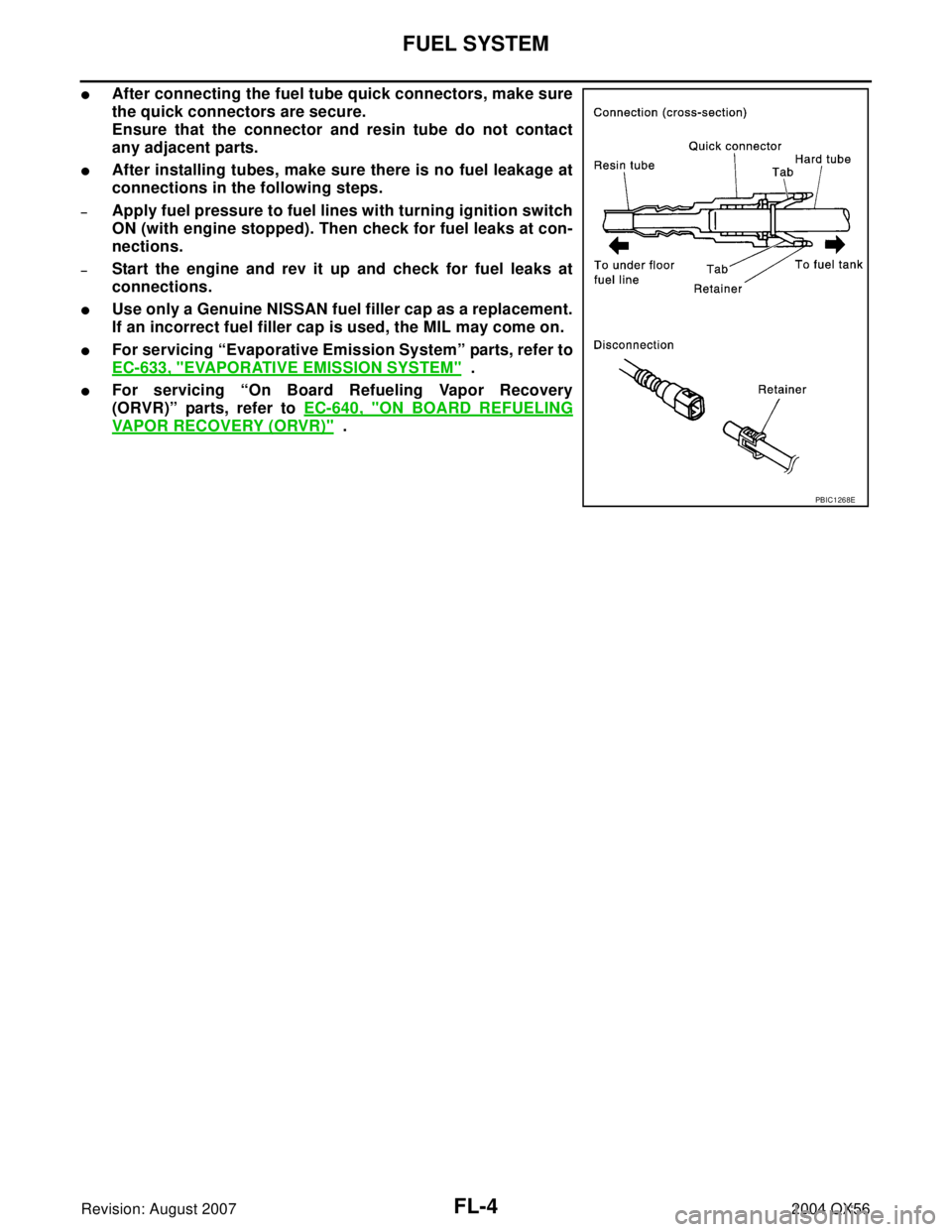
�After connecting the fuel tube quick connectors, make sure
the quick connectors are secure.
Ensure that the connector and resin tube do not contact
any adjacent parts.
�After installing tubes, make sure there is no fuel leakage at
connections in the following steps.
–Apply fuel pressure to fuel lines with turning ignition switch
ON (with engine stopped). Then check for fuel leaks at con-
nections.
–Start the engine and rev it up and check for fuel leaks at
connections.
�Use only a Genuine NISSAN fuel filler cap as a replacement.
If an incorrect fuel filler cap is used, the MIL may come on.
�For servicing “Evaporative Emission System” parts, refer to
EC-633, "
EVAPORATIVE EMISSION SYSTEM" .
�For servicing “On Board Refueling Vapor Recovery
(ORVR)” parts, refer to EC-640, "
ON BOARD REFUELING
VAPOR RECOVERY (ORVR)" .
PBIC1268E