Page 2044 of 3371
SERVICE DATA AND SPECIFICATIONS (SDS)
FFD-33
C
E
F
G
H
I
J
K
L
MA
B
FFD
Revision: August 20072004 QX56
Pinion Height Adjusting Washer
*: Always check with the Parts Department for the latest parts information.Available drive pinion
height adjusting
washersThickness mm (in) Package part number*
1.22 (0.048)
1.24 (0.049)
1.27 (0.050)
1.30 (0.051)
1.32 (0.052)38154 8S111
1.35 (0.053)
1.37 (0.054)
1.40 (0.055)
1.42 (0.056)
1.45 (0.057)38154 8S112
1.47 (0.058)
1.50 (0.059)
1.52 (0.060)
1.55 (0.061)
1.57 (0.062)38154 8S113
1.60 (0.063)
1.63 (0.064)
1.65 (0.065)
1.68 (0.066)
1.70 (0.067)38154 8S114
1.73 (0.068)
1.75 (0.069)
1.78 (0.070)
1.80 (0.071)
1.83 (0.072)38154 8S115
Page 2045 of 3371
FFD-34
SERVICE DATA AND SPECIFICATIONS (SDS)
Revision: August 20072004 QX56
Page 2046 of 3371

FL-1
FUEL SYSTEM
B ENGINE
CONTENTS
C
D
E
F
G
H
I
J
K
L
M
SECTION FL
A
FL
Revision: August 20072004 QX56 PREPARATION ........................................................... 2
Special Service Tools ............................................... 2
Commercial Service Tool ......................................... 2
FUEL SYSTEM ........................................................... 3
Checking Fuel Lines ................................................. 3
General Precautions ................................................ 3
FUEL LEVEL SENSOR UNIT, FUEL FILTER AND
FUEL PUMP ASSEMBLY ........................................... 5
Removal and Installation .......................................... 5
REMOVAL ............................................................. 5
INSTALLATION ..................................................... 8
INSPECTION AFTER INSTALLATION ................. 8FUEL TANK ................................................................ 9
Removal and Installation .......................................... 9
REMOVAL ........................................................... 10
INSTALLATION ................................................... 13
INSPECTION AFTER INSTALLATION ................ 13
SERVICE DATA AND SPECIFICATIONS (SDS) ...... 14
Standard and Limit .................................................. 14
Page 2047 of 3371
FL-2Revision: August 2007
PREPARATION
2004 QX56
PREPARATIONPFP:00002
Special Service ToolsEBS00IKL
The actual shapes of the Kent-Moore tools may differ from those of the special tools illustrated here.
Commercial Service ToolEBS00IKM
Tool number
(Kent-Moore No.)
Tool nameDescription
—
(J-46536)
Fuel tank lock ring toolRemoving and installing fuel tank lock ring
LBIA0398E
Tool nameDescription
Power toolLoosening bolts and nuts
PBIC0190E
Page 2059 of 3371
FL-14Revision: August 2007
SERVICE DATA AND SPECIFICATIONS (SDS)
2004 QX56
SERVICE DATA AND SPECIFICATIONS (SDS)PFP:00030
Standard and LimitEBS00IKR
Fuel tank capacity
105.8 (28 US gal, 23 1/4 Imp gal)
Page 2060 of 3371

FSU-1
FRONT SUSPENSION
E SUSPENSION
CONTENTS
C
D
F
G
H
I
J
K
L
M
SECTION FSU
A
B
FSU
Revision: August 20072004 QX56 PRECAUTIONS .......................................................... 2
Precautions .............................................................. 2
PREPARATION ........................................................... 3
Special Service Tools ............................................... 3
Commercial Service Tools ........................................ 3
NOISE, VIBRATION, AND HARSHNESS (NVH)
TROUBLESHOOTING ................................................ 4
NVH Troubleshooting Chart ..................................... 4
FRONT SUSPENSION ASSEMBLY ........................... 5
Components ............................................................. 5
ON-VEHICLE SERVICE ............................................. 6
Front Suspension Parts ............................................ 6
Front Wheel Alignment ............................................. 6
PRELIMINARY INSPECTION ............................... 6
GENERAL INFORMATION AND RECOMMEN-
DATIONS .............................................................. 6
THE ALIGNMENT PROCESS .............................. 7
CAMBER AND CASTER ....................................... 7
TOE-IN .................................................................. 8
FRONT WHEEL TURNING ANGLE ..................... 8
COIL SPRING AND SHOCK ABSORBER ............... 10
Removal and Installation ........................................ 10
REMOVAL ........................................................... 10
INSTALLATION ................................................... 10
Disassembly and Assembly ................................... 10
DISASSEMBLY ................................................... 10
INSPECTION AFTER DISASSEMBLY ............... 10
ASSEMBLY ..........................................................11STABILIZER BAR ..................................................... 12
Removal and Installation ........................................ 12
REMOVAL ........................................................... 12
INSPECTION AFTER REMOVAL ....................... 12
INSTALLATION ................................................... 12
UPPER LINK ............................................................. 13
Removal and Installation ........................................ 13
REMOVAL ........................................................... 13
INSPECTION AFTER REMOVAL ....................... 13
INSTALLATION ................................................... 13
LOWER LINK ............................................................ 14
Removal and Installation ........................................ 14
REMOVAL ........................................................... 14
INSPECTION AFTER REMOVAL ....................... 14
INSTALLATION ................................................... 14
UPPER BALL JOINT AND LOWER BALL JOINT ... 15
Removal and Installation ........................................ 15
Inspection ............................................................... 15
SWINGING FORCE ............................................ 15
TURNING FORCE ............................................... 15
VERTICAL END PLAY ........................................ 16
KNUCKLE ................................................................. 17
On-Vehicle Inspection and Service ......................... 17
Removal and Installation ........................................ 17
REMOVAL ........................................................... 17
INSPECTION AFTER REMOVAL ....................... 18
INSTALLATION ................................................... 19
SERVICE DATA AND SPECIFICATIONS (SDS) ...... 20
General Specifications (Front) ................................ 20
Wheel Alignment (Unladen*
1 ) ................................ 20
Ball Joint ................................................................. 21
Wheelarch Height (Unladen*
1 ) .............................. 21
Page 2062 of 3371
PREPARATION
FSU-3
C
D
F
G
H
I
J
K
L
MA
B
FSU
Revision: August 20072004 QX56
PREPARATIONPFP:00002
Special Service ToolsEES0010E
The actual shapes of Kent-Moore tools may differ from those of special service tools illustrated here.
Commercial Service ToolsEES0010F
Tool number
(Kent-Moore No.)
Tool nameDescription
ST29020001
(J-24319-01)
Gear arm pullerRemoving ball joint for knuckle spindle
a: 34 mm (1.34 in)
b: 6.5 mm (0.256 in)
c: 61.5 mm (2.421 in)
HT72520000
(J-25730-A)
Ball joint removerRemoving tie-rod outer end
NT694
NT146
Tool nameDescription
Attachment wheel alignment Measure wheel alignment
a: Screw M24 x 1.5 pitch
b: 35 mm (1.38 in) dia.
c: 65 mm (2.56 in) dia.
d: 56 mm (2.20 in)
e: 12 mm (0.47 in)
Spring compressor Removing and installing coil spring
Power toolLoosening bolts and nuts
NT148
NT717
PBIC0190E
Page 2065 of 3371

FSU-6
ON-VEHICLE SERVICE
Revision: August 20072004 QX56
ON-VEHICLE SERVICEPFP:00000
Front Suspension PartsEES0010I
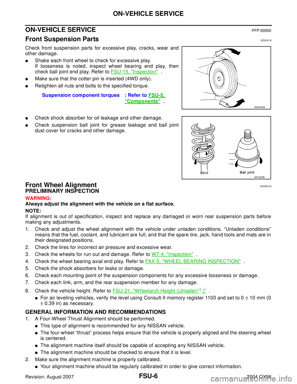
Check front suspension parts for excessive play, cracks, wear and
other damage.
�Shake each front wheel to check for excessive play.
If looseness is noted, inspect wheel bearing end play, then
check ball joint end play. Refer to FSU-15, "
Inspection" .
�Make sure that the cotter pin is inserted (4WD only).
�Retighten all nuts and bolts to the specified torque.
�Check shock absorber for oil leakage and other damage.
�Check suspension ball joint for grease leakage and ball joint
dust cover for cracks and other damage.
Front Wheel AlignmentEES0010J
PRELIMINARY INSPECTION
WAR NIN G:
Always adjust the alignment with the vehicle on a flat surface.
NOTE:
If alignment is out of specification, inspect and replace any damaged or worn rear suspension parts before
making any adjustments.
1. Check and adjust the wheel alignment with the vehicle under unladen conditions. “Unladen conditions”
means that the fuel, coolant, and lubricant are full; and that the spare tire, jack, hand tools and mats are in
their designated positions.
2. Check the tires for incorrect air pressure and excessive wear.
3. Check the wheels for run out and damage. Refer to WT-4, "
Inspection" .
4. Check the wheel bearing axial end play. Refer to FAX-5, "
WHEEL BEARING INSPECTION" .
5. Check the shock absorbers for leaks or damage.
6. Check each mounting point of the suspension components for any excessive looseness or damage.
7. Check each link, arm, and the rear suspension member for any damage.
8. Check the vehicle height. Refer to FSU-21, "
Wheelarch Height (Unladen*1 )" .
�For air leveling vehicles, verify the level using Consult-II memory register 1103 and set to 0 ± 10 mm (0
± 0.39 in) as necessary.
GENERAL INFORMATION AND RECOMMENDATIONS
1. A Four-Wheel Thrust Alignment should be performed.
�This type of alignment is recommended for any NISSAN vehicle.
�The four-wheel “thrust” process helps ensure that the vehicle is properly aligned and the steering wheel
is centered.
�The alignment machine itself should be capable of accepting any NISSAN vehicle.
�The alignment machine should be checked to ensure that it is level.
2. Make sure the alignment machine is properly calibrated.
�Your alignment machine should be regularly calibrated in order to give correct information.Suspension component torques : Refer to FSU-5,
"Components" .
SM A52 5A
SFA392B