Page 3275 of 3371

TF-150
ASSEMBLY
Revision: August 20072004 QX56
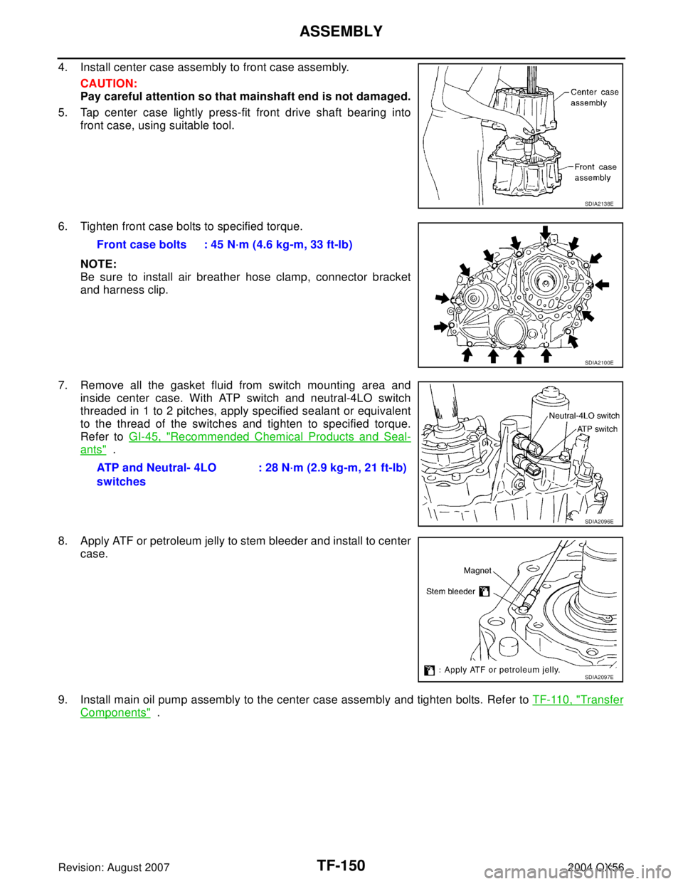
4. Install center case assembly to front case assembly.
CAUTION:
Pay careful attention so that mainshaft end is not damaged.
5. Tap center case lightly press-fit front drive shaft bearing into
front case, using suitable tool.
6. Tighten front case bolts to specified torque.
NOTE:
Be sure to install air breather hose clamp, connector bracket
and harness clip.
7. Remove all the gasket fluid from switch mounting area and
inside center case. With ATP switch and neutral-4LO switch
threaded in 1 to 2 pitches, apply specified sealant or equivalent
to the thread of the switches and tighten to specified torque.
Refer to GI-45, "
Recommended Chemical Products and Seal-
ants" .
8. Apply ATF or petroleum jelly to stem bleeder and install to center
case.
9. Install main oil pump assembly to the center case assembly and tighten bolts. Refer to TF-110, "
Transfer
Components" .
SDIA2138E
Front case bolts : 45 N·m (4.6 kg-m, 33 ft-lb)
SDIA2100E
ATP and Neutral- 4LO
switches: 28 N·m (2.9 kg-m, 21 ft-lb)
SDIA2096E
SDIA2097E
Page 3277 of 3371
TF-152
ASSEMBLY
Revision: August 20072004 QX56
15. Install air breather into rear case.
16. Apply specified Anaerobic Liquid Gasket or equivalent to entire
rear case mounting surface of center case as shown. Refer to
GI-45, "
Recommended Chemical Products and Sealants" .
CAUTION:
Be careful not to allow Liquid Gasket to the stem bleeder
hole.
NOTE:
Remove all foreign materials such as water, oil, and grease from
center case and rear case mating surfaces.
17. Install rear case to center case, and tighten bolts to specified
torque.
18. Installation of the remaining components is in the reverse order of removal.
SDIA2206E
Center case bolts : 45 N·m 4.6 kg-m, 33 ft-lb)
SDIA2100E
Page 3285 of 3371

WT-6
WHEEL AND TIRE ASSEMBLY
Revision: August 20072004 QX56
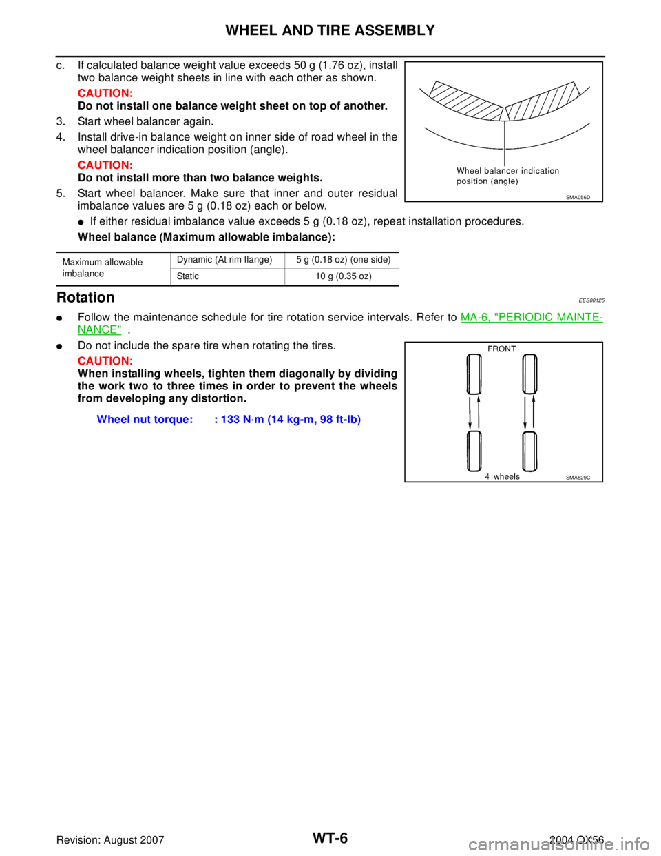
c. If calculated balance weight value exceeds 50 g (1.76 oz), install
two balance weight sheets in line with each other as shown.
CAUTION:
Do not install one balance weight sheet on top of another.
3. Start wheel balancer again.
4. Install drive-in balance weight on inner side of road wheel in the
wheel balancer indication position (angle).
CAUTION:
Do not install more than two balance weights.
5. Start wheel balancer. Make sure that inner and outer residual
imbalance values are 5 g (0.18 oz) each or below.
�If either residual imbalance value exceeds 5 g (0.18 oz), repeat installation procedures.
Wheel balance (Maximum allowable imbalance):
RotationEES00125
�Follow the maintenance schedule for tire rotation service intervals. Refer to MA-6, "PERIODIC MAINTE-
NANCE" .
�Do not include the spare tire when rotating the tires.
CAUTION:
When installing wheels, tighten them diagonally by dividing
the work two to three times in order to prevent the wheels
from developing any distortion.
Maximum allowable
imbalanceDynamic (At rim flange) 5 g (0.18 oz) (one side)
Static 10 g (0.35 oz)
SM A05 6D
Wheel nut torque: : 133 N·m (14 kg-m, 98 ft-lb)
SM A82 9C
Page 3342 of 3371

FRONT WIPER AND WASHER SYSTEM
WW-29
C
D
E
F
G
H
I
J
L
MA
B
WW
Revision: August 20072004 QX56
Removal and Installation of Front Wiper Arms, Adjustment of Wiper Arms Stop
Location
EKS007FH
REMOVAL
1. Operate the wiper motor, and stop it at the auto stop position.
2. Remove the wiper arm mounting covers.
3. Remove the wiper arm mounting nuts, then remove the wiper arms.
INSTALLATION
1. Prior to wiper arm installation, turn on wiper switch to operate
wiper motor and then turn it “OFF” (Auto Stop).
2. Lift the blade up and then set it down onto glass surface to set
the blade center to clearance “L1” and “L2” immediately before
tightening nut.
3. Eject washer fluid. Turn on wiper switch to operate wiper motor
and then turn it “OFF”.
4. Ensure that wiper blades stop within clearance “L1” and “L2”.
�Before reinstalling wiper arm, clean up the pivot area as illus-
trated. This will reduce possibility of wiper arm looseness.
�Tighten wiper arm nuts to specified torque.
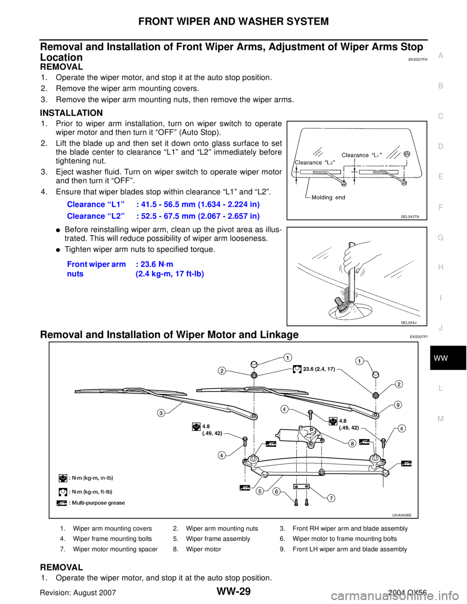
Removal and Installation of Wiper Motor and Linkage EKS007FI
REMOVAL
1. Operate the wiper motor, and stop it at the auto stop position.Clearance “L1” : 41.5 - 56.5 mm (1.634 - 2.224 in)
Clearance “L2” : 52.5 - 67.5 mm (2.067 - 2.657 in)
Front wiper arm
nuts: 23.6 N·m
(2.4 kg-m, 17 ft-lb)
SEL543TA
SEL024J
LKIA0408E
1. Wiper arm mounting covers 2. Wiper arm mounting nuts 3. Front RH wiper arm and blade assembly
4. Wiper frame mounting bolts 5. Wiper frame assembly 6. Wiper motor to frame mounting bolts
7. Wiper motor mounting spacer 8. Wiper motor 9. Front LH wiper arm and blade assembly
Page 3370 of 3371
HORN
WW-57
C
D
E
F
G
H
I
J
L
MA
B
WW
Revision: August 20072004 QX56
Removal and InstallationEKS007GC
REMOVAL
1. Open the hood.
2. Disconnect horn connector.
3. Remove horn bolt and remove horn from vehicle.
INSTALLATION
1. Tighten horn bolt to specified torque.
2. Reconnect horn connector.
LKIA0419E
Horn bolt : 17 N·m (1.7 kg-m, 13 ft-lb)