Page 2776 of 3371
POWER STEERING GEAR AND LINKAGE
PS-25
C
D
E
F
H
I
J
K
L
MA
B
PS
Revision: August 20072004 QX56
21. Install new boot clamps and crimp securely using Tool.
CAUTION:
Do not reuse boot clamps.
22. Install cylinder tubes to gear housing assembly.
23. Install lock nut and outer socket to inner socket.
24. Tighten lightly tie-rod in specified length “L”, then tighten lock nut
at specified torque. Refer to PS-17, "
Disassembly and Assem-
bly" . Reconfirm if tie-rod length is within limit of specified length
“L”.
CAUTION:
Perform toe-in adjustment after this procedure. Length
achieved after toe-in adjustment is not necessarily the
value given here.Tool number : KV40107300 ( — )
AST 1 39
Inner socket length “L” : 115.2 mm (4.54 in)
SGIA0167E
Page 2777 of 3371

PS-26
POWER STEERING OIL PUMP
Revision: August 20072004 QX56
POWER STEERING OIL PUMPPFP:49110
On-Vehicle Inspection and ServiceEGS000MW
CHECKING RELIEF OIL PRESSURE
CAUTION:
Before starting work, confirm belt tension is proper.
1. Connect Tool between oil pump discharge connector and high
pressure hose and then bleed air from the hydraulic circuit.
2. Start engine. Allow engine to run until tank temperature reaches 50 – 80°C (122 – 176°F).
CAUTION:
�Warm up engine with shut-off valve fully opened. If engine is started with shut-off valve closed,
fluid pressure in power steering pump increases to maximum. This will raise fluid temperature
excessively.
�Be careful not to contact hose with belt when engine is started.
3. With engine at idle, close shut-off valve and read the relief oil pressure.
CAUTION:
Do not close shut-off valve of pressure gauge for more than 10 seconds.
4. After measurement, open shut-off valve slowly.
�If relief oil pressure is outside the specification, disassemble and repair oil pump. Refer to PS-17, "Dis-
assembly and Assembly" .
5. After inspection, disconnect oil pressure gauge and oil pressure gauge adapter from hydraulic circuit, con-
nect oil pump discharge connector and high pressure hose. Add fluid and bleed air from hydraulic circuit
thoroughly. Refer to PS-6, "
Air Bleeding Hydraulic System" .
Removal and InstallationEG S0 0 0MX
REMOVAL
1. Drain power steering fluid from reservoir tank.
2. Remove engine room cover. Refer to EM-11, "
Removal and Installation" .
3. Remove air duct assembly. Refer to EM-14, "
Removal and Installation" .
4. Remove power steering reservoir tank.
5. Remove serpentine drive belt belt from auto tensioner and power steering pump. Refer to EM-12,
"Removal and Installation" .
6. Disconnect pressure sensor electrical connector.
7. Remove high pressure and low pressure piping from power steering oil pump. Refer to PS-31, "
HYDRAU-
LIC LINE" .
8. Remove mounting bolts, then remove power steering pump.
INSTALLATION
Installation is in the reverse order of removal. Refer to PS-31, "HYDRAULIC LINE" for tightening torque.
�After installation, bleed air. Refer to PS-6, "Air Bleeding Hydraulic System" .
NOTE:
Belt tension is automatic and requires no adjustment.
Tool number:
Pressure gauge and shut-off valveKV48103500
(J26357 and J26357-10)
Oil pump sideConnector A and
O-ringKV48105300-4 and 5295262U10
(—)
Eye-bolt and O-ringKV48105300-3 and 5295262U00
(—)
High pressure
piping sideConnector B and
O-ringKV48105300-1 and 5295262U00
(—)
NutKV48105300-2
( — )
Relief oil pressure
: 9.0 – 9.8 mPa (91.77 – 99.93 kg/cm2 , 1305.34 – 1421.37 psi)
SGIA0570E
Page 2781 of 3371
PS-30
POWER STEERING OIL PUMP
Revision: August 20072004 QX56
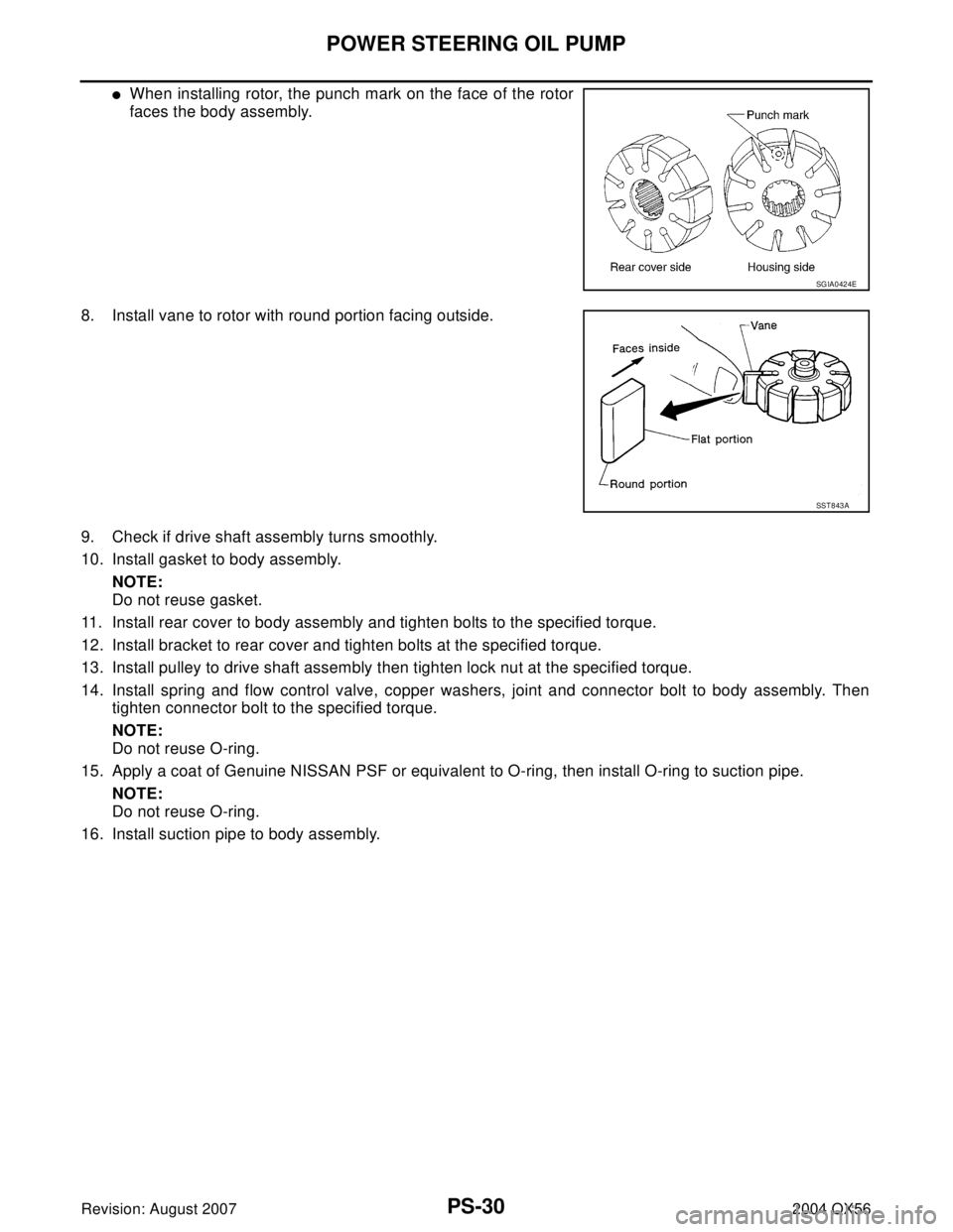
�When installing rotor, the punch mark on the face of the rotor
faces the body assembly.
8. Install vane to rotor with round portion facing outside.
9. Check if drive shaft assembly turns smoothly.
10. Install gasket to body assembly.
NOTE:
Do not reuse gasket.
11. Install rear cover to body assembly and tighten bolts to the specified torque.
12. Install bracket to rear cover and tighten bolts at the specified torque.
13. Install pulley to drive shaft assembly then tighten lock nut at the specified torque.
14. Install spring and flow control valve, copper washers, joint and connector bolt to body assembly. Then
tighten connector bolt to the specified torque.
NOTE:
Do not reuse O-ring.
15. Apply a coat of Genuine NISSAN PSF or equivalent to O-ring, then install O-ring to suction pipe.
NOTE:
Do not reuse O-ring.
16. Install suction pipe to body assembly.
SGIA0424E
SST 8 43 A
Page 2783 of 3371
PS-32
HYDRAULIC LINE
Revision: August 20072004 QX56
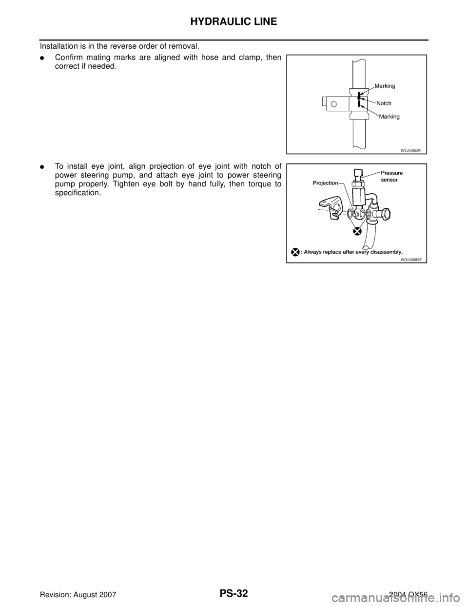
Installation is in the reverse order of removal.
�Confirm mating marks are aligned with hose and clamp, then
correct if needed.
�To install eye joint, align projection of eye joint with notch of
power steering pump, and attach eye joint to power steering
pump properly. Tighten eye bolt by hand fully, then torque to
specification.
SGIA0563E
WGIA0089E
Page 2785 of 3371
PS-34
SERVICE DATA AND SPECIFICATIONS (SDS)
Revision: August 20072004 QX56
Inspection After Installation
Steering Outer Socket and Inner SocketEGS000NH
Unit: mm (in) Range “A”61.3 mm (2.41 in)
Tilt mechanism range (Manual tilt) 3° per notch at 5 steps
WGIA0083E
Tie-rod ball joint outer socketSwinging torque 0.3 − 2.9 N·m (0.03 − 0.29 kg-m, 3 − 25 in-lb)
Measurement on spring balance�Measuring point: cotter pin hole of stud4.84 − 46.7 N (0.50 − 4.7 kg, 4 − 34 lb)
Rotating torque 0.3 − 2.9 N·m (0.03 − 0.29 kg-m, 3 − 25 in-lb)
Axial end play 0.5 mm (0.020 in) or less
Tie-rod ball joint inner socketSwinging torque 1.0 − 7.8 N·m (0.11 − 0.79 kg-m, 9 − 69 in-lb)
Measurement on spring balance
�Measuring point: "L" mark see above,
"L"=83.2 mm (3.276 in).12.1 − 93.7 N (1.3 − 9.5 kg, 9 − 69 lb)
Axial end play 0.2 mm (0.08 in) or less
SGIA0358E
Inner socket length “L” 115.2 (4.54)
SGIA0167E
Page 2803 of 3371
 “AIR BAG” and “SEAT
BELT PRE-TENSIONER”
EIS0 02 WC
The Supplemental Re")
RF-2
PRECAUTIONS
Revision: August 20072004 QX56
PRECAUTIONSPFP:00001
Precautions for Supplemental Restraint System (SRS) “AIR BAG” and “SEAT
BELT PRE-TENSIONER”
EIS0 02 WC
The Supplemental Restraint System such as “AIR BAG” and “SEAT BELT PRE-TENSIONER”, used along
with a front seat belt, helps to reduce the risk or severity of injury to the driver and front passenger for certain
types of collision. This system includes seat belt switch inputs and dual stage front air bag modules. The SRS
system uses the seat belt switches to determine the front air bag deployment, and may only deploy one front
air bag, depending on the severity of a collision and whether the front occupants are belted or unbelted.
Information necessary to service the system safely is included in the SRS and SB section of this Service Man-
ual.
WAR NIN G:
�To avoid rendering the SRS inoperative, which could increase the risk of personal injury or death
in the event of a collision which would result in air bag inflation, all maintenance must be per-
formed by an authorized NISSAN/INFINITI dealer.
�Improper maintenance, including incorrect removal and installation of the SRS, can lead to per-
sonal injury caused by unintentional activation of the system. For removal of Spiral Cable and Air
Bag Module, see the SRS section.
�Do not use electrical test equipment on any circuit related to the SRS unless instructed to in this
Service Manual. SRS wiring harnesses can be identified by yellow and/or orange harnesses or
harness connectors.
Precautions EIS0 02 WD
�Disconnect both battery cables in advance.
�Never tamper with or force air bag lid open, as this may adversely affect air bag performance.
�Be careful not to scratch pad and other parts.
�When removing or disassembling any part, be careful not to damage or deform it. Protect parts which may
get in the way with cloth.
�When removing parts with a screwdriver or other tool, protect parts by wrapping them with vinyl or tape.
�Keep removed parts protected with cloth.
�If a clip is deformed or damaged, replace it.
�If an unreusable part is removed, replace it with a new one.
�Tighten bolts and nuts firmly to the specified torque.
�After re-assembly has been completed, make sure each part functions correctly.
�Remove stains in the following way.
Water-soluble stains:
Dip a soft cloth in warm water, and then squeeze it tightly. After wiping the stain, wipe with a soft dry cloth.
Oil stain:
Dissolve a synthetic detergent in warm water (density of 2 to 3% or less), dip the cloth, then clean off the stain
with the cloth. Next, dip the cloth in fresh water and squeeze it tightly. Then clean off the detergent completely.
Then wipe the area with a soft dry cloth.
�Do not use any organic solvent, such as thinner or benzine.
Page 2834 of 3371
PREPARATION
RFD-3
C
E
F
G
H
I
J
K
L
MA
B
RFD
Revision: August 20072004 QX56
Drift
KV38100200
(J-26233)Installing side bearing inner race
a: 65 mm (2.55 in) dia.
b: 49 mm (1.92 in) dia.
Drive pinion flange wrench
KV40104000
(—)Removing and installing drive pinion nut
a: 85 mm (3.35 in) dia.
b: 65 mm (2.56 in) dia.
Slide hammer
ST36230000
(J-25840-A)Removing side flange
Axle stand
KV40104100
(—)Removing side flange
Slide hammer
HT72400000
(—)Removing differential case assembly
Drift
ST35325000
(—)Installing drive pinion rear bearing outer race
(use with ST30621000)
Preload gauge
ST3127S000
(J-25765-A)
1. Torque wrench
GG91030000
(J-25765)
2. Socket adapter (1/2 in)
HT62940000
(—)
3. Socket adapter (3/8 in)
HT62900000
(—)Measuring pinion bearing preload and total
preload Tool name
Tool number
(Kent-Moore No.)Description
ZZA1143D
NT659
ZZA0803D
ZZA0804D
S-NT125
S-NT090
NT124
Page 2838 of 3371

FRONT OIL SEAL
RFD-7
C
E
F
G
H
I
J
K
L
MA
B
RFD
Revision: August 20072004 QX56
7. Remove the front oil seal using Tool as shown.
INSTALLATION
1. Apply multi-purpose grease to the sealing lips of the new oil
seal, then press the front oil seal into the carrier using Tool as
shown.
CAUTION:
�Keep the oil seal even when installing, do not tilt the oil
seal when pressing it in.
�Discard the old oil seal, always install a new oil seal.
2. Align the matching mark of the drive pinion with the matching
mark “B” of the companion flange as shown, then install the
companion flange.
3. Apply oil or multi-purpose grease on the drive pinion threads
and the seating surface of drive pinion nut.
4. Install drive pinion nut using Tool.
�Tighten the drive pinion nut to the minimum specified torque.
Final drive pinion nut torque will be determined when adjust-
ing the total preload. Refer to RFD-12, "
TOTAL PRELOAD" .
CAUTION:
The drive pinion nut is not reusable. Use a new drive pinion
nut for installation.
5. Install the rear propeller shaft. Refer to PR-8, "
Removal and Installation" .
6. Connect the rear drive shafts to the rear final drive. Tighten the drive shaft inside flange bolts to specifica-
tion.
7. Check the rear final drive fluid and add fluid as necessary. Refer to MA-24, "
Checking Final Drive Oil" . Tool number : ST33290001 (J-34286)
LDIA0107E
Tool number : ST15310000 ( — )
LDIA0108E
SDIA0270E
Tool number : KV40104000 ( — )
Drive pinion nut : 167 - 372 N·m (17 - 38 kg-m,
124 - 274 ft-lb)
LDIA0105E
Drive shaft inside flange bolt : 118 N·m (12 kg-m, 87 ft-lb)


Revision: August 20072004 QX56
Inspection After Installation
Steering Outer Socket and Inner SocketEGS000NH
Unit: mm (in) Range “A”61.3 mm (2.41 in)
Til")
Installing side bearing inner race
a: 65 mm (2.55 in) dia.
b: 49 mm (1.92 in) dia.
Drive pinion fl")