Page 3327 of 3371
WW-14
FRONT WIPER AND WASHER SYSTEM
Revision: August 20072004 QX56
OK or NG
OK >> GO TO 2.
NG >> If fuse or fusible link is blown, be sure to eliminate cause of malfunction before installing new fuse
or fusible link. Refer to PG-4, "
POWER SUPPLY ROUTING CIRCUIT" .
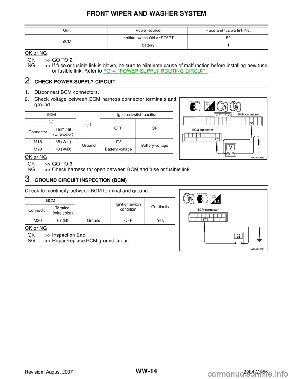
2. CHECK POWER SUPPLY CIRCUIT
1. Disconnect BCM connectors.
2. Check voltage between BCM harness connector terminals and
ground.
OK or NG
OK >> GO TO 3.
NG >> Check harness for open between BCM and fuse or fusible link.
3. GROUND CIRCUIT INSPECTION (BCM)
Check for continuity between BCM terminal and ground.
OK or NG
OK >> Inspection End.
NG >> Repair/replace BCM ground circuit.
BCMIgnition switch ON or START 59
Batteryf Unit Power source Fuse and fusible link No.
BCM
(–)Ignition switch position
(+)
OFF ON
ConnectorTe r m i n a l
(wire color)
M18 38 (W/L)
Ground0V
Battery voltage
M20 70 (W/B) Battery voltage
WKIA2089E
BCM
Ignition switch
conditionContinuity
ConnectorTe r m i n a l
(wire color)
M20 67 (B) Ground OFF Yes
WKIA2090E
Page 3328 of 3371
FRONT WIPER AND WASHER SYSTEM
WW-15
C
D
E
F
G
H
I
J
L
MA
B
WW
Revision: August 20072004 QX56
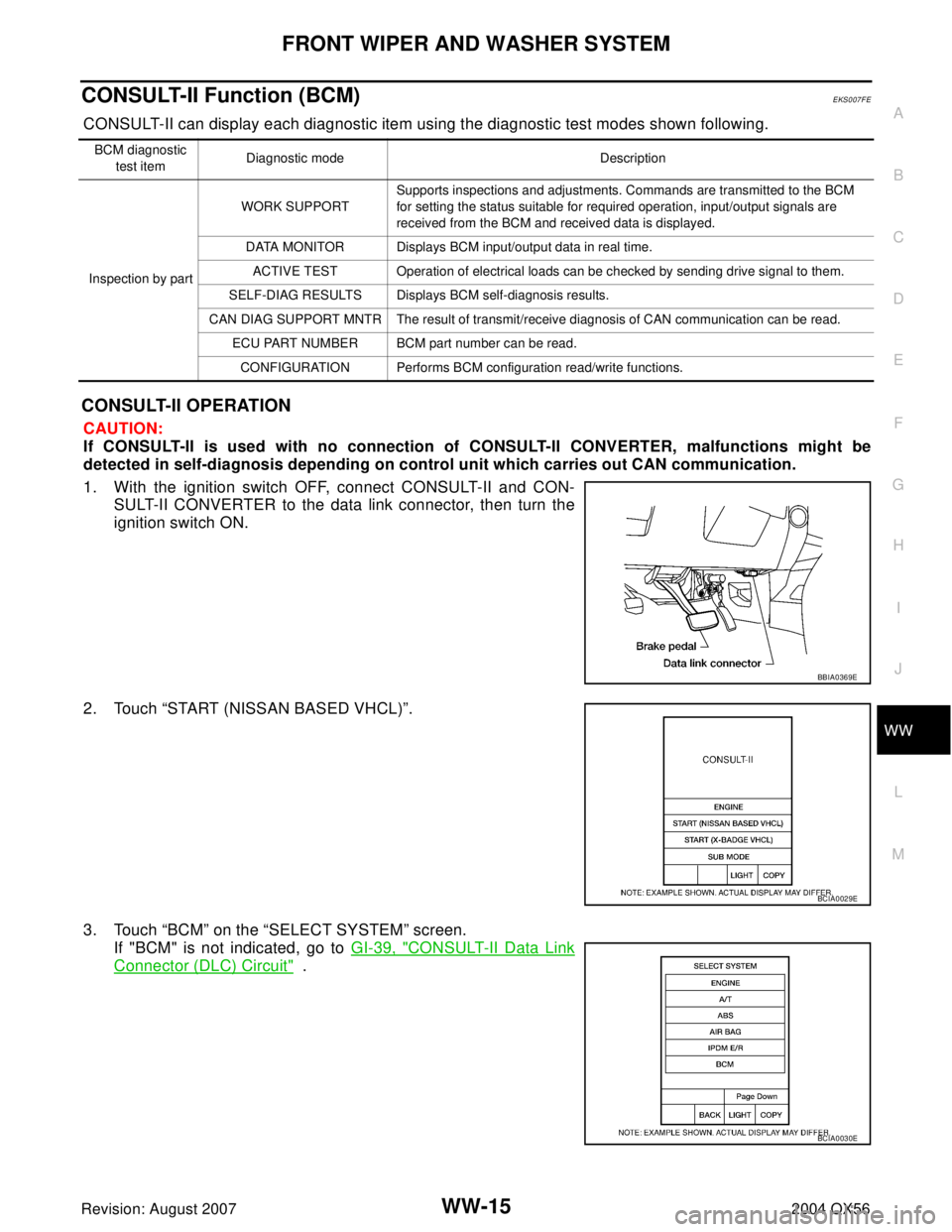
CONSULT-II Function (BCM)EKS007FE
CONSULT-II can display each diagnostic item using the diagnostic test modes shown following.
CONSULT-II OPERATION
CAUTION:
If CONSULT-II is used with no connection of CONSULT-II CONVERTER, malfunctions might be
detected in self-diagnosis depending on control unit which carries out CAN communication.
1. With the ignition switch OFF, connect CONSULT-II and CON-
SULT-II CONVERTER to the data link connector, then turn the
ignition switch ON.
2. Touch “START (NISSAN BASED VHCL)”.
3. Touch “BCM” on the “SELECT SYSTEM” screen.
If "BCM" is not indicated, go to GI-39, "
CONSULT-II Data Link
Connector (DLC) Circuit" .
BCM diagnostic
test itemDiagnostic mode Description
Inspection by partWORK SUPPORTSupports inspections and adjustments. Commands are transmitted to the BCM
for setting the status suitable for required operation, input/output signals are
received from the BCM and received data is displayed.
DATA MONITOR Displays BCM input/output data in real time.
ACTIVE TEST Operation of electrical loads can be checked by sending drive signal to them.
SELF-DIAG RESULTS Displays BCM self-diagnosis results.
CAN DIAG SUPPORT MNTR The result of transmit/receive diagnosis of CAN communication can be read.
ECU PART NUMBER BCM part number can be read.
CONFIGURATION Performs BCM configuration read/write functions.
BBIA0369E
BCIA0029E
BCIA0030E
Page 3332 of 3371
FRONT WIPER AND WASHER SYSTEM
WW-19
C
D
E
F
G
H
I
J
L
MA
B
WW
Revision: August 20072004 QX56
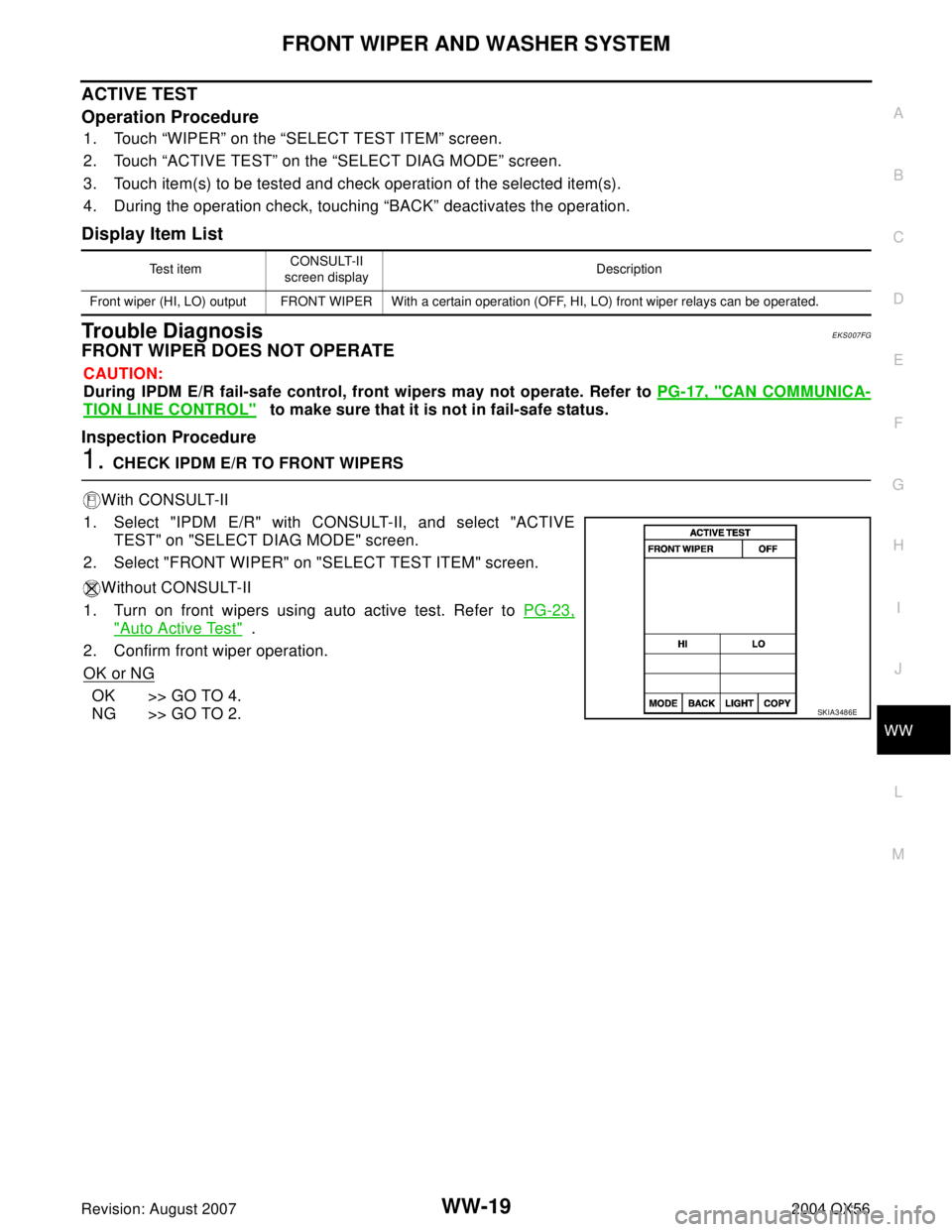
ACTIVE TEST
Operation Procedure
1. Touch “WIPER” on the “SELECT TEST ITEM” screen.
2. Touch “ACTIVE TEST” on the “SELECT DIAG MODE” screen.
3. Touch item(s) to be tested and check operation of the selected item(s).
4. During the operation check, touching “BACK” deactivates the operation.
Display Item List
Trouble DiagnosisEKS007FG
FRONT WIPER DOES NOT OPERATE
CAUTION:
During IPDM E/R fail-safe control, front wipers may not operate. Refer to PG-17, "
CAN COMMUNICA-
TION LINE CONTROL" to make sure that it is not in fail-safe status.
Inspection Procedure
1. CHECK IPDM E/R TO FRONT WIPERS
With CONSULT-II
1. Select "IPDM E/R" with CONSULT-II, and select "ACTIVE
TEST" on "SELECT DIAG MODE" screen.
2. Select "FRONT WIPER" on "SELECT TEST ITEM" screen.
Without CONSULT-II
1. Turn on front wipers using auto active test. Refer to PG-23,
"Auto Active Test" .
2. Confirm front wiper operation.
OK or NG
OK >> GO TO 4.
NG >> GO TO 2.
Te s t i t e mCONSULT-II
screen displayDescription
Front wiper (HI, LO) output FRONT WIPER With a certain operation (OFF, HI, LO) front wiper relays can be operated.
SKIA3486E
Page 3333 of 3371
WW-20
FRONT WIPER AND WASHER SYSTEM
Revision: August 20072004 QX56
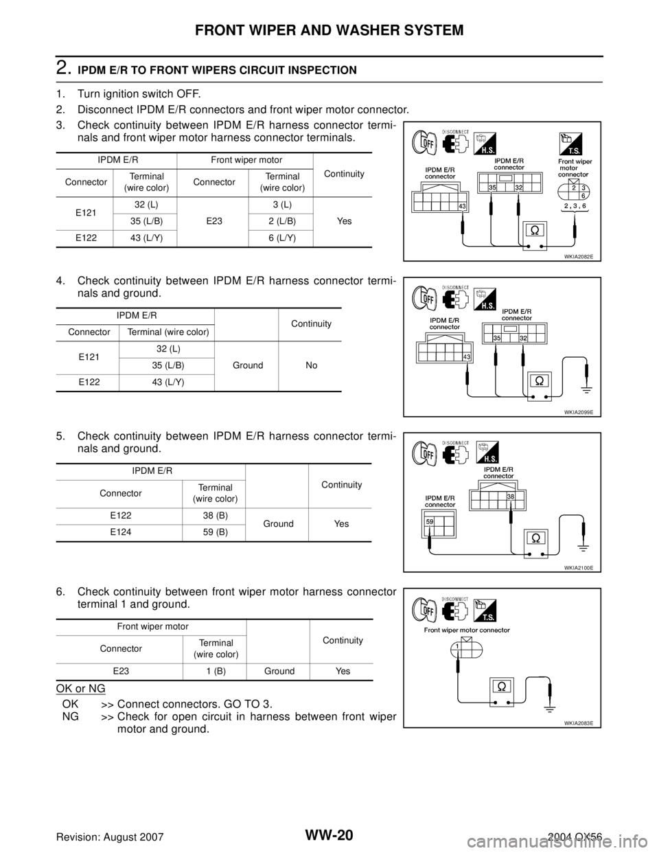
2. IPDM E/R TO FRONT WIPERS CIRCUIT INSPECTION
1. Turn ignition switch OFF.
2. Disconnect IPDM E/R connectors and front wiper motor connector.
3. Check continuity between IPDM E/R harness connector termi-
nals and front wiper motor harness connector terminals.
4. Check continuity between IPDM E/R harness connector termi-
nals and ground.
5. Check continuity between IPDM E/R harness connector termi-
nals and ground.
6. Check continuity between front wiper motor harness connector
terminal 1 and ground.
OK or NG
OK >> Connect connectors. GO TO 3.
NG >> Check for open circuit in harness between front wiper
motor and ground.
IPDM E/R Front wiper motor
Continuity
ConnectorTe r m i n a l
(wire color)ConnectorTe r m i n a l
(wire color)
E12132 (L)
E233 (L)
Ye s 35 (L/B) 2 (L/B)
E122 43 (L/Y) 6 (L/Y)
WKIA2082E
IPDM E/R
Continuity
Connector Terminal (wire color)
E12132 (L)
Ground No 35 (L/B)
E122 43 (L/Y)
WKIA2099E
IPDM E/R
Continuity
ConnectorTe r m i n a l
(wire color)
E122 38 (B)
Ground Yes
E124 59 (B)
WKIA2100E
Front wiper motor
Continuity
ConnectorTe r m i n a l
(wire color)
E23 1 (B) Ground Yes
WKIA2083E
Page 3334 of 3371
FRONT WIPER AND WASHER SYSTEM
WW-21
C
D
E
F
G
H
I
J
L
MA
B
WW
Revision: August 20072004 QX56
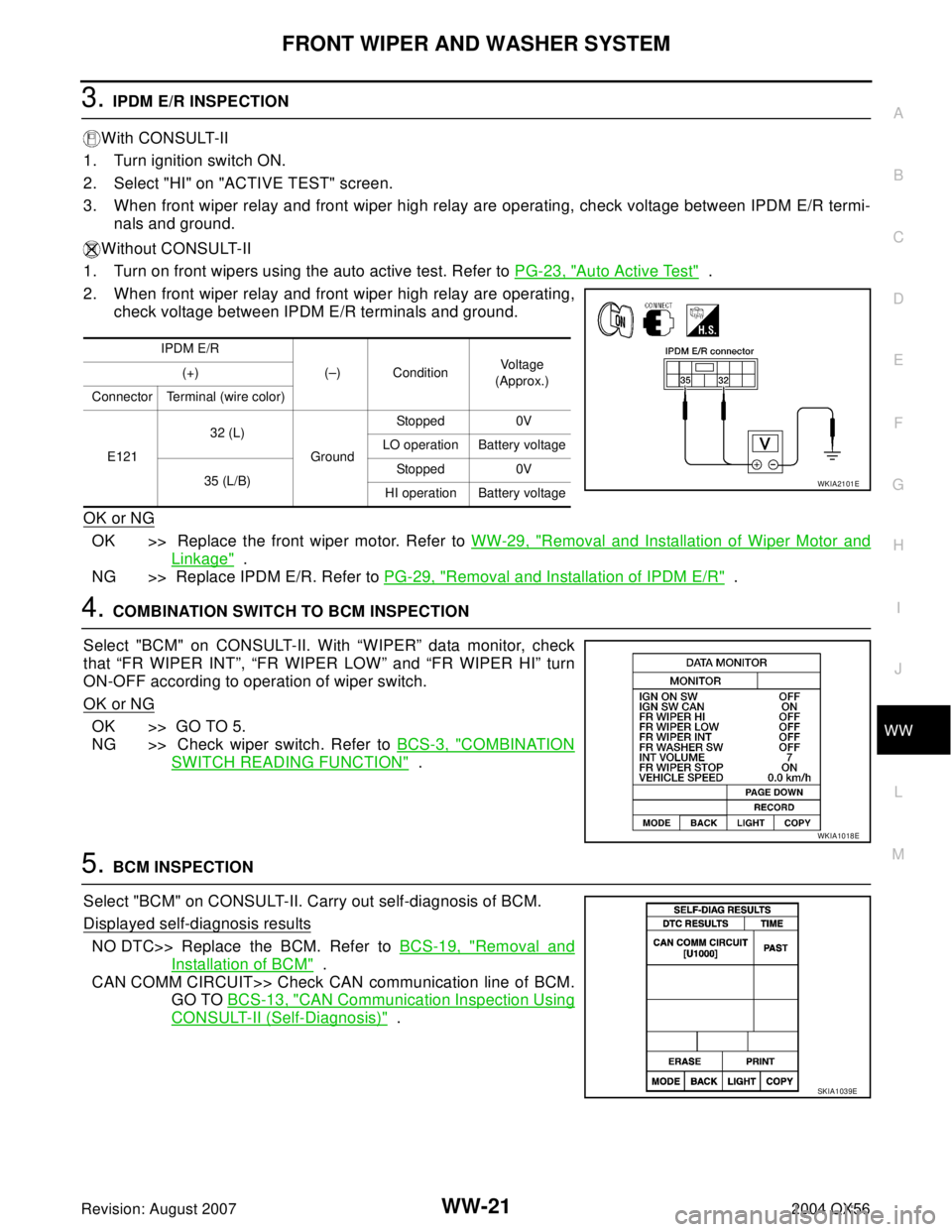
3. IPDM E/R INSPECTION
With CONSULT-II
1. Turn ignition switch ON.
2. Select "HI" on "ACTIVE TEST" screen.
3. When front wiper relay and front wiper high relay are operating, check voltage between IPDM E/R termi-
nals and ground.
Without CONSULT-II
1. Turn on front wipers using the auto active test. Refer to PG-23, "
Auto Active Test" .
2. When front wiper relay and front wiper high relay are operating,
check voltage between IPDM E/R terminals and ground.
OK or NG
OK >> Replace the front wiper motor. Refer to WW-29, "Removal and Installation of Wiper Motor and
Linkage" .
NG >> Replace IPDM E/R. Refer to PG-29, "
Removal and Installation of IPDM E/R" .
4. COMBINATION SWITCH TO BCM INSPECTION
Select "BCM" on CONSULT-II. With “WIPER” data monitor, check
that “FR WIPER INT”, “FR WIPER LOW” and “FR WIPER HI” turn
ON-OFF according to operation of wiper switch.
OK or NG
OK >> GO TO 5.
NG >> Check wiper switch. Refer to BCS-3, "
COMBINATION
SWITCH READING FUNCTION" .
5. BCM INSPECTION
Select "BCM" on CONSULT-II. Carry out self-diagnosis of BCM.
Displayed self-diagnosis results
NO DTC>> Replace the BCM. Refer to BCS-19, "Removal and
Installation of BCM" .
CAN COMM CIRCUIT>> Check CAN communication line of BCM.
GO TO BCS-13, "
CAN Communication Inspection Using
CONSULT-II (Self-Diagnosis)" .
IPDM E/R
(–) ConditionVo l ta g e
(Approx.) (+)
Connector Terminal (wire color)
E12132 (L)
GroundStopped 0V
LO operation Battery voltage
35 (L/B)Stopped 0V
HI operation Battery voltage
WKIA2101E
WKIA1018E
SKIA1039E
Page 3335 of 3371
WW-22
FRONT WIPER AND WASHER SYSTEM
Revision: August 20072004 QX56
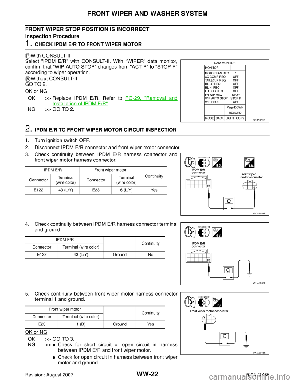
FRONT WIPER STOP POSITION IS INCORRECT
Inspection Procedure
1. CHECK IPDM E/R TO FRONT WIPER MOTOR
With CONSULT-II
Select "IPDM E/R" with CONSULT-II. With “WIPER” data monitor,
confirm that "WIP AUTO STOP" changes from "ACT P" to "STOP P"
according to wiper operation.
Without CONSULT-II
GO TO 2.
OK or NG
OK >> Replace IPDM E/R. Refer to PG-29, "Removal and
Installation of IPDM E/R" .
NG >> GO TO 2.
2. IPDM E/R TO FRONT WIPER MOTOR CIRCUIT INSPECTION
1. Turn ignition switch OFF.
2. Disconnect IPDM E/R connector and front wiper motor connector.
3. Check continuity between IPDM E/R harness connector and
front wiper motor harness connector.
4. Check continuity between IPDM E/R harness connector terminal
and ground.
5. Check continuity between front wiper motor harness connector
terminal 1 and ground.
OK or NG
OK >> GO TO 3.
NG >>
�Check for short circuit or open circuit in harness
between IPDM E/R and front wiper motor.
�Check for open circuit in harness between front wiper
motor and ground.
SKIA5301E
IPDM E/R Front wiper motor
Continuity
ConnectorTe r m i n a l
(wire color)ConnectorTe r m i n a l
(wire color)
E122 43 (L/Y) E23 6 (L/Y) Yes
WKIA2084E
IPDM E/R
Continuity
Connector Terminal (wire color)
E122 43 (L/Y) Ground No
WKIA2088E
Front wiper motor
Continuity
Connector Terminal (wire color)
E23 1 (B) Ground Yes
WKIA2083E
Page 3336 of 3371

FRONT WIPER AND WASHER SYSTEM
WW-23
C
D
E
F
G
H
I
J
L
MA
B
WW
Revision: August 20072004 QX56
3. IPDM E/R INSPECTION
With CONSULT-II
1. Connect IPDM E/R connector and front wiper motor connector.
2. Turn ignition switch ON.
3. Select "LO" on "ACTIVE TEST" screen.
4. When front wipers are operating and when stopped, measure voltage between IPDM E/R terminal 43 and
ground.
Without CONSULT-II
1. Connect IPDM E/R connector and front wiper motor connector.
2. Turn on front wipers using the auto active test. Refer to PG-23, "
Auto Active Test" .
3. When front wipers are operating and when stopped, measure
voltage between IPDM E/R terminal 43 and ground.
OK or NG
OK >> Replace IPDM E/R. Refer to PG-29, "Removal and Installation of IPDM E/R" .
NG >> Replace front wiper motor. Refer to WW-29, "
Removal and Installation of Wiper Motor and Link-
age" .
ONLY FRONT WIPER LOW DOES NOT OPERATE
Inspection Procedure
1. CHECK IPDM E/R TO FRONT WIPERS
With CONSULT-II
1. Select "IPDM E/R" with CONSULT-II, and select "ACTIVE
TEST" on "SELECT DIAG MODE" screen.
2. Select "FRONT WIPER" on "SELECT TEST ITEM" screen.
3. Select "LO" on "ACTIVE TEST" screen.
4. Confirm front wiper low operation.
Without CONSULT-II
1. Turn on front wipers using auto active test. Refer to PG-23,
"Auto Active Test" .
2. Confirm front wiper low operation.
OK or NG
OK >> GO TO 4.
NG >> GO TO 2.
IPDM E/R
(–) ConditionVo l ta g e
(Approx.) (+)
ConnectorTe r m i n a l
(wire color)
E122 43 (L/Y) GroundWiper operating Fluctuating
Wiper stopped 0V
WKIA2085E
SKIA3486E
Page 3337 of 3371
WW-24
FRONT WIPER AND WASHER SYSTEM
Revision: August 20072004 QX56
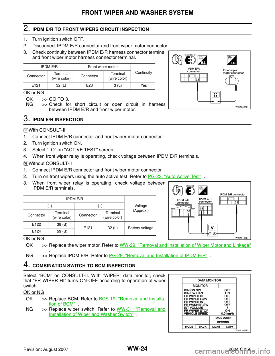
2. IPDM E/R TO FRONT WIPERS CIRCUIT INSPECTION
1. Turn ignition switch OFF.
2. Disconnect IPDM E/R connector and front wiper motor connector.
3. Check continuity between IPDM E/R harness connector terminal
and front wiper motor harness connector terminal.
OK or NG
OK >> GO TO 3.
NG >> Check for short circuit or open circuit in harness
between IPDM E/R and front wiper motor.
3. IPDM E/R INSPECTION
With CONSULT-II
1. Connect IPDM E/R connector and front wiper motor connector.
2. Turn ignition switch ON.
3. Select "LO" on "ACTIVE TEST" screen.
4. When front wiper relay is operating, check voltage between IPDM E/R terminals.
Without CONSULT-II
1. Connect IPDM E/R connector and front wiper motor connector.
2. Turn on front wipers using the auto active test. Refer to PG-23, "
Auto Active Test" .
3. When front wiper relay is operating, check voltage between
IPDM E/R terminals.
OK or NG
OK >> Replace the wiper motor. Refer to WW-29, "Removal and Installation of Wiper Motor and Linkage"
.
NG >> Replace IPDM E/R. Refer to PG-29, "
Removal and Installation of IPDM E/R" .
4. COMBINATION SWITCH TO BCM INSPECTION
Select "BCM" on CONSULT-II. With “WIPER” data monitor, check
that “FR WIPER HI” turns ON-OFF according to operation of wiper
switch.
OK or NG
OK >> Replace BCM. Refer to BCS-19, "Removal and Installa-
tion of BCM" .
NG >> Replace wiper switch. Refer to WW-31, "
Removal and
Installation of Wiper and Washer Switch" .
IPDM E/R Front wiper motor
Continuity
ConnectorTe r m i n a l
(wire color)ConnectorTe r m i n a l
(wire color)
E121 32 (L) E23 3 (L) Yes
WKIA2086E
IPDM E/R
Vo ltag e
(Approx.) (–) (+)
ConnectorTe r m i n a l
(wire color)ConnectorTe r m i n a l
(wire color)
E122 38 (B)
E121 32 (L) Battery voltage
E124 59 (B)
WKIA3198E
WKIA1018E