Page 3240 of 3371
CENTER CASE
TF-115
C
E
F
G
H
I
J
K
L
MA
B
TF
Revision: August 20072004 QX56
11. Remove C-rings from mainshaft bearing, using suitable tool.
FRONT DRIVE SHAFT AND DRIVE CHAIN
1. With front drive shaft held by one hand as shown, remove using
a suitable tool, remove front drive shaft with drive chain.
CAUTION:
Do not tap drive chain with a plastic hammer.
2. Remove the front drive shaft front bearing using Tool.
3. Remove the front drive shaft rear bearing using Tool.
SDIA2105E
SMT900C
To o l n u m b e r
A : ST33052000 ( — )
B : ST30031000 ( — )
SDIA2106E
To o l n u m b e r
A : ST33052000 ( — )
B : ST30031000 ( — )
SDIA2107E
Page 3241 of 3371
TF-116
CENTER CASE
Revision: August 20072004 QX56
MAINSHAFT AND CLUTCH DRUM
1. Set center case on press stand. Remove mainshaft from center
case.
2. Remove thrust needle bearing from press flange.
3. Remove snap ring from mainshaft, using suitable tool.
4. Press flange as shown, using Tool. Press drift until snap ring is
out of place.
SDIA2108E
SDIA2109E
SDIA2 110 E
Tool number
A : ST22452000 (J-34335)
B : ST30911000 ( — )
C : KV31103300 ( — )
SD I A 2 111E
Page 3242 of 3371
CENTER CASE
TF-117
C
E
F
G
H
I
J
K
L
MA
B
TF
Revision: August 20072004 QX56
5. Remove snap ring from mainshaft, using suitable tool.
6. Remove press flange from mainshaft.
7. Remove return spring assembly from clutch hub.
8. Remove each plate from clutch drum.
9. Remove snap ring from mainshaft.
SDIA2 112 E
SMT910C
SM T9 11 C
SMT912C
SDIA2 113 E
Page 3243 of 3371
TF-118
CENTER CASE
Revision: August 20072004 QX56
10. Tap mainshaft, using suitable tool to remove it from clutch drum
and clutch hub.
11. Remove needle bearing and spacer from the mainshaft.
12. Remove the snap ring from the clutch hub.
CLUTCH PISTON
1. Remove oil pressure check plug from oil pressure check port.
2. Apply air gradually from oil pressure check port, and remove
clutch piston from center case.
SMT914C
WDIA0101E
SDIA2 115 E
SDIA2 116 E
Page 3246 of 3371
CENTER CASE
TF-121
C
E
F
G
H
I
J
K
L
MA
B
TF
Revision: August 20072004 QX56
8. Remove O-rings from each solenoid valve, switch and terminal body.
9. Place control valve with lower body facing up, remove two
mounting bolts, and then remove lower body and separator plate
from upper body.
CAUTION:
Be careful not to drop relief balls. Detach lower body care-
fully.
10. Make sure reverse balls, relief balls and relief springs, accumu-
lator pistons and valve springs are securely installed as shown,
and remove them.
11. Remove retainer plates.
12. Remove each plug (2), control valve (3) and spring (4) from the
upper body (5).
SDIA2125E
SDIA2126E
SDIA2127E
WDIA0284E
Page 3247 of 3371
TF-122
CENTER CASE
Revision: August 20072004 QX56
MAINSHAFT REAR BEARING
1. Remove mainshaft rear bearing from center case, using Tool
MAIN OIL PUMP
1. Remove bolts as shown to detach main oil pump.
2. Remove outer gear, inner gear, and main oil pump cover from
main oil pump housing.
3. Remove seal ring from the main oil pump cover.Tool number : KV38100300 (J-25523)
SDIA2129E
SDIA2130E
SDIA2131E
SDIA2132E
Page 3255 of 3371
TF-130
FRONT CASE
Revision: August 20072004 QX56
13. Remove the mainshaft front bearing from the front case, using
Tool.
Tool number : ST33200000 (J-26082)
SDIA2178E
Page 3256 of 3371

FRONT CASE
TF-131
C
E
F
G
H
I
J
K
L
MA
B
TF
Revision: August 20072004 QX56
FRONT CASEPFP:33107
InspectionEDS00191
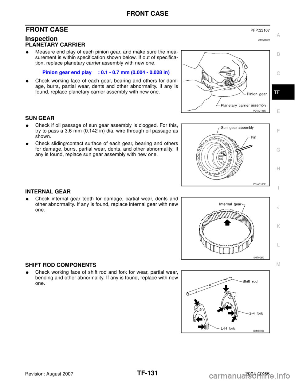
PLANETARY CARRIER
�Measure end play of each pinion gear, and make sure the mea-
surement is within specification shown below. If out of specifica-
tion, replace planetary carrier assembly with new one.
�Check working face of each gear, bearing and others for dam-
age, burrs, partial wear, dents and other abnormality. If any is
found, replace planetary carrier assembly with new one.
SUN GEAR
�Check if oil passage of sun gear assembly is clogged. For this,
try to pass a 3.6 mm (0.142 in) dia. wire through oil passage as
shown.
�Check sliding/contact surface of each gear, bearing and others
for damage, burrs, partial wear, dents, and other abnormality. If
any is found, replace sun gear assembly with new one.
INTERNAL GEAR
�Check internal gear teeth for damage, partial wear, dents and
other abnormality. If any is found, replace internal gear with new
one.
SHIFT ROD COMPONENTS
�Check working face of shift rod and fork for wear, partial wear,
bending and other abnormality. If any is found, replace with new
one.Pinion gear end play : 0.1 - 0.7 mm (0.004 - 0.028 in)
PDIA0185E
PDIA0186E
SMT008D
SMT009D