Page 2067 of 3371

FSU-8
ON-VEHICLE SERVICE
Revision: August 20072004 QX56
TOE-IN
WAR NIN G:
�Always perform the following procedure on a flat surface.
�Make sure that no person is in front of the vehicle before pushing it.
1. Bounce the front of vehicle up and down to stabilize the vehicle height (posture).
2. Push the vehicle straight ahead about 5 m (16 ft).
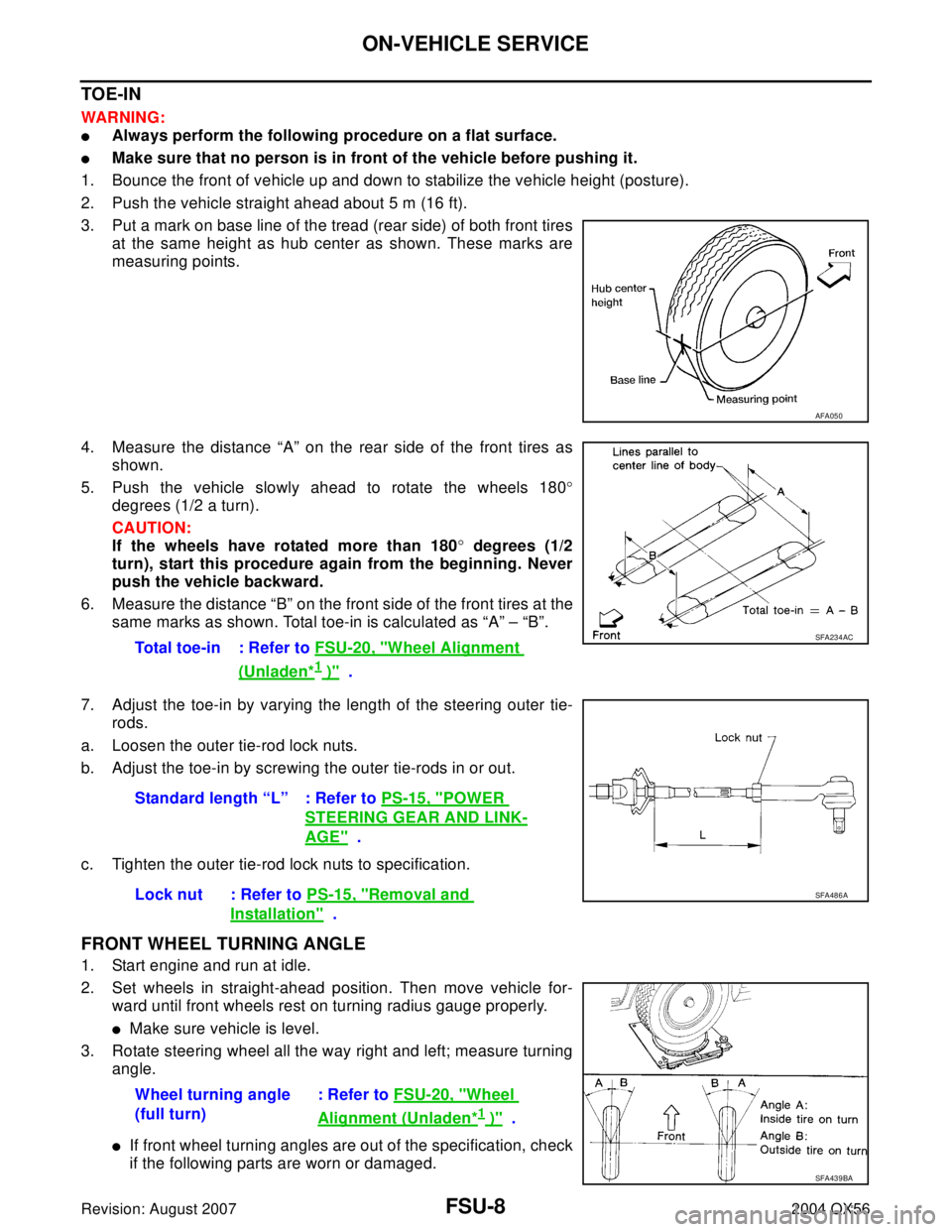
3. Put a mark on base line of the tread (rear side) of both front tires
at the same height as hub center as shown. These marks are
measuring points.
4. Measure the distance “A” on the rear side of the front tires as
shown.
5. Push the vehicle slowly ahead to rotate the wheels 180°
degrees (1/2 a turn).
CAUTION:
If the wheels have rotated more than 180° degrees (1/2
turn), start this procedure again from the beginning. Never
push the vehicle backward.
6. Measure the distance “B” on the front side of the front tires at the
same marks as shown. Total toe-in is calculated as “A” – “B”.
7. Adjust the toe-in by varying the length of the steering outer tie-
rods.
a. Loosen the outer tie-rod lock nuts.
b. Adjust the toe-in by screwing the outer tie-rods in or out.
c. Tighten the outer tie-rod lock nuts to specification.
FRONT WHEEL TURNING ANGLE
1. Start engine and run at idle.
2. Set wheels in straight-ahead position. Then move vehicle for-
ward until front wheels rest on turning radius gauge properly.
�Make sure vehicle is level.
3. Rotate steering wheel all the way right and left; measure turning
angle.
�If front wheel turning angles are out of the specification, check
if the following parts are worn or damaged.
AFA05 0
Total toe-in : Refer to FSU-20, "Wheel Alignment
(Unladen*1 )" .
SFA234AC
Standard length “L” : Refer to PS-15, "POWER
STEERING GEAR AND LINK-
AGE" .
Lock nut : Refer to PS-15, "
Removal and
Installation" .
SFA486A
Wheel turning angle
(full turn): Refer to FSU-20, "Wheel
Alignment (Unladen*1 )" .
SFA439BA
Page 2608 of 3371

ENGINE OIL
LU-7
C
D
E
F
G
H
I
J
K
L
MA
LU
Revision: August 20072004 QX56
ENGINE OILPFP:KLA92
InspectionEBS00I4J
OIL LEVEL
�Before starting the engine make sure the vehicle is parked on a
flat and level surface, then check the oil level. If the engine is
already running, turn it off and allow 10 minutes before check-
ing.
�Check that the oil level is within the low (L) and high (H) range
as indicated on the dipstick.
�If the engine oil level is out of range, add oil as necessary. Refer
to GI-45, "
Recommended Chemical Products and Sealants" .
OIL APPEARANCE
�Check the engine oil for a white milky appearance or excessive contamination.
�If the engine oil is milky, it is highly probable that it is contaminated with engine coolant. Repair the broken
parts.
OIL LEAKAGE
Check for oil leakage around the following areas.
�Oil pan
�Oil pan drain plug
�Oil pressure sensor
�Oil filter
�Oil cooler
�Intake valve timing control cover
�Intake valve timing control solenoid valve
�Front cover
�Mating surface between cylinder block and cylinder head
�Mating surface between cylinder head and rocker cover
�Crankshaft oil seal (front and rear)
OIL PRESSURE CHECK
WA RN ING:
�Be careful not to burn yourself, as engine oil may be hot.
�Put the selector lever in the Park “P” position.
1. Check the engine oil level. Refer to LU-7, "
OIL LEVEL" .
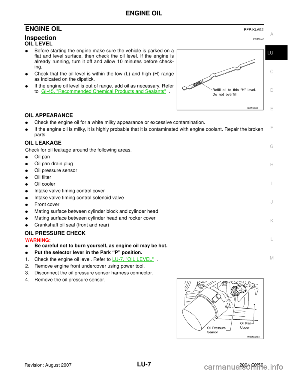
2. Remove engine front undercover using power tool.
3. Disconnect the oil pressure sensor harness connector.
4. Remove the oil pressure sensor.
SM A95 4C
WBIA0538E
Page 2644 of 3371

CHASSIS AND BODY MAINTENANCE
MA-27
C
D
E
F
G
H
I
J
K
MA
B
MA
Revision: August 20072004 QX56
Wheel Balance
Tire RotationELS0010P
1. Rotate the tires on each side from front to back as shown.
�Do not include the same spare tire when rotating the tires.
2. Adjust the tire pressure to specification. Refer to WT-33, "
Tire" .
3. After the tire rotation, retighten the wheel nuts after the vehicle has been driven for 1,000 km (600 miles),
and also after a wheel and tire have been installed such as after repairing a flat tire.
Checking Brake Fluid Level and LeaksELS0010Q
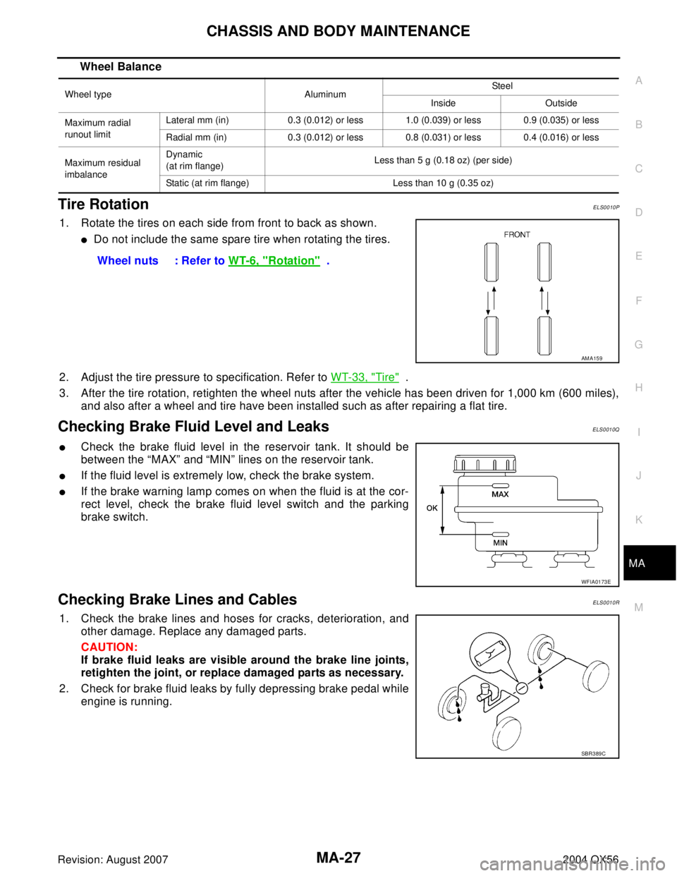
�Check the brake fluid level in the reservoir tank. It should be
between the “MAX” and “MIN” lines on the reservoir tank.
�If the fluid level is extremely low, check the brake system.
�If the brake warning lamp comes on when the fluid is at the cor-
rect level, check the brake fluid level switch and the parking
brake switch.
Checking Brake Lines and CablesELS0010R
1. Check the brake lines and hoses for cracks, deterioration, and
other damage. Replace any damaged parts.
CAUTION:
If brake fluid leaks are visible around the brake line joints,
retighten the joint, or replace damaged parts as necessary.
2. Check for brake fluid leaks by fully depressing brake pedal while
engine is running.
Wheel type AluminumSteel
Inside Outside
Maximum radial
runout limitLateral mm (in) 0.3 (0.012) or less 1.0 (0.039) or less 0.9 (0.035) or less
Radial mm (in) 0.3 (0.012) or less 0.8 (0.031) or less 0.4 (0.016) or less
Maximum residual
imbalanceDynamic
(at rim flange)Less than 5 g (0.18 oz) (per side)
Static (at rim flange) Less than 10 g (0.35 oz)
Wheel nuts : Refer to WT-6, "Rotation" .
AM A15 9
WFIA0173E
SBR3 89 C
Page 2886 of 3371

REAR SUSPENSION ASSEMBLY
RSU-27
C
D
F
G
H
I
J
K
L
MA
B
RSU
Revision: August 20072004 QX56
Wheel Alignment InspectionEES0011H
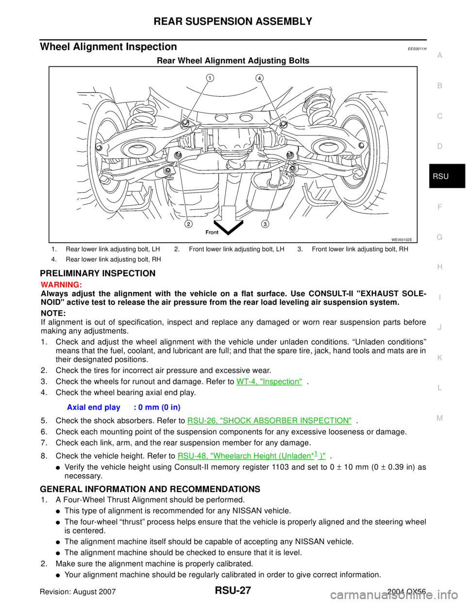
Rear Wheel Alignment Adjusting Bolts
PRELIMINARY INSPECTION
WA RN ING:
Always adjust the alignment with the vehicle on a flat surface. Use CONSULT-II "EXHAUST SOLE-
NOID" active test to release the air pressure from the rear load leveling air suspension system.
NOTE:
If alignment is out of specification, inspect and replace any damaged or worn rear suspension parts before
making any adjustments.
1. Check and adjust the wheel alignment with the vehicle under unladen conditions. “Unladen conditions”
means that the fuel, coolant, and lubricant are full; and that the spare tire, jack, hand tools and mats are in
their designated positions.
2. Check the tires for incorrect air pressure and excessive wear.
3. Check the wheels for runout and damage. Refer to WT-4, "
Inspection" .
4. Check the wheel bearing axial end play.
5. Check the shock absorbers. Refer to RSU-26, "
SHOCK ABSORBER INSPECTION" .
6. Check each mounting point of the suspension components for any excessive looseness or damage.
7. Check each link, arm, and the rear suspension member for any damage.
8. Check the vehicle height. Refer to RSU-48, "
Wheelarch Height (Unladen*1 )" .
�Verify the vehicle height using Consult-II memory register 1103 and set to 0 ± 10 mm (0 ± 0.39 in) as
necessary.
GENERAL INFORMATION AND RECOMMENDATIONS
1. A Four-Wheel Thrust Alignment should be performed.
�This type of alignment is recommended for any NISSAN vehicle.
�The four-wheel “thrust” process helps ensure that the vehicle is properly aligned and the steering wheel
is centered.
�The alignment machine itself should be capable of accepting any NISSAN vehicle.
�The alignment machine should be checked to ensure that it is level.
2. Make sure the alignment machine is properly calibrated.
�Your alignment machine should be regularly calibrated in order to give correct information.
WEIA0102E
1. Rear lower link adjusting bolt, LH 2. Front lower link adjusting bolt, LH 3. Front lower link adjusting bolt, RH
4. Rear lower link adjusting bolt, RH
Axial end play : 0 mm (0 in)
Page 3283 of 3371
WT-4
WHEEL
Revision: August 20072004 QX56
WHEELPFP:40300
InspectionEES00123
1. Check tires for wear and improper inflation.
2. Check wheels for deformation, cracks and other damage. If
deformed, remove wheel and check wheel runout.
a. Remove tire from wheel and mount wheel on a tire balance
machine.
b. Set dial indicator as shown in the illustration. Refer to WT-33,
"Road Wheel" .
3. Check front wheel bearings for looseness.
4. Check front suspension for looseness.
SFA975B