Page 418 of 3371
 service couplers to a
CFC-12 (R-12) A/C system. The HFC-134a (")
PRECAUTIONS
ATC-13
C
D
E
F
G
H
I
K
L
MA
B
AT C
Revision: August 20072004 QX56
SERVICE COUPLERS
Never attempt to connect HFC-134a (R-134a) service couplers to a
CFC-12 (R-12) A/C system. The HFC-134a (R-134a) couplers will
not properly connect to the CFC-12 (R-12) system. If an improper
connection is attempted, discharging and contamination may occur.
REFRIGERANT WEIGHT SCALE
Verify that no refrigerant other than HFC134a (R-134a) and specified
lubricants have been used with the scale. If the scale controls refrig-
erant flow electronically, the hose fitting must be 1/2”-16 ACME.
CHARGING CYLINDER
Using a charging cylinder is not recommended. Refrigerant may be vented into air from cylinder's top valve
when filling the cylinder with refrigerant. Also, the accuracy of the cylinder is generally less than that of an
electronic scale or of quality recycle/recharge equipment.
Wiring Diagrams and Trouble DiagnosisEJS002BO
When you read wiring diagrams, refer to the following:
�GI-15, "How to Read Wiring Diagrams"
�PG-4, "POWER SUPPLY ROUTING CIRCUIT"
When you perform trouble diagnosis, refer to the following:
�GI-11, "How to Follow Trouble Diagnoses"
�GI-27, "How to Perform Efficient Diagnosis for an Electrical Incident"
Shut-off valve rotation A/C service valve
Clockwise Open
Counterclockwise Close
RHA273D
RHA274D
Page 419 of 3371

ATC-14
PREPARATION
Revision: August 20072004 QX56
PREPARATIONPFP:00002
Special Service ToolsEJS002BP
The actual shapes of Kent-Moore tools may differ from those of special service tools illustrated here.
HFC-134a (R-134a) Service Tools and EquipmentEJS002BQ
Never mix HFC-134a refrigerant and/or its specified lubricant with CFC-12 (R-12) refrigerant and/or its lubri-
cant.
Separate and non-interchangeable service equipment must be used for handling each type of refrigerant/lubri-
cant.
Refrigerant container fittings, service hose fittings and service equipment fittings (equipment which handles
refrigerant and/or lubricant) are different between CFC-12 (R-12) and HFC-134a (R-134a). This is to avoid
mixed use of the refrigerants/lubricant.
Adapters that convert one size fitting to another must never be used refrigerant/lubricant contamination will
occur and compressor failure will result.
Tool number
(Kent-Moore No.)
Tool nameDescription
—
(J-38873-A)
Drive plate installerInstalling pulley and drive plate
KV99233130
(J-29884)
Pulley pullerRemoving pulley
WJIA0367E
LHA172
Tool number
(Kent-Moore No.)
Tool nameDescription
HFC-134a (R-134a) refrigerant Container color: Light blue
Container marking: HFC-134a (R-
134a)
Fitting size: Thread size
�large container 1/2"-16 ACME
KLH00-PAGS0
(—)
Nissan A/C System Oil Type DH-
PSType: Poly alkylene glycol oil (PAG),
type DH-PS
Application: HFC-134a (R-134a)
swash plate compressors (Nissan
only)
Lubricity: 40 m (1.4 US fl oz, 1.4 Imp
fl oz)
KV991J0130
(ACR2005-NI)
ACR A/C Service CenterRefrigerant recovery, recycling and re-
charging
S-NT196
S-NT197
WJIA0293E
Page 420 of 3371

Electronic refrigerant leak detectorPower supply:
�DC 12V (battery terminal)
(J-43926)
Refrigerant dye leak dete")
PREPARATION
ATC-15
C
D
E
F
G
H
I
K
L
MA
B
AT C
Revision: August 20072004 QX56
(J-41995)
Electronic refrigerant leak detectorPower supply:
�DC 12V (battery terminal)
(J-43926)
Refrigerant dye leak detection kit
Kit includes:
(J-42220)
UV lamp and UV safety goggles
(J-41459)
Refrigerant dye injector
(J-41447)
HFC-134a (R-134a) Fluorescent
leak detection dye
(Box of 24, 1/4 ounce bottles)
(J-43872)
Refrigerant dye cleanerPower supply:
�DC 12V (battery terminal)
(J-42220)
UV lamp and UV safety gogglesPower supply:
�DC 12V (battery terminal)
For checking refrigerant leak when flu-
orescent dye is installed in A/C system.
Includes: UV lamp and UV safety gog-
gles
(J-41447)
HFC-134a (R-134a) Fluorescent
leak detection dye
(Box of 24, 1/4 ounce bottles)Application: For HFC-134a (R-134a)
PAG oil
Container: 1/4 ounce (7.4cc) bottle
(Includes self-adhesive dye identifica-
tion labels for affixing to vehicle after
charging system with dye.)
(J-41459)
HFC-134a (R-134a) Dye injector
Use with J-41447, 1/4 ounce bottleFor injecting 1/4 ounce of fluorescent
leak detection dye into A/C system.
(J-43872)
Refrigerant dye cleanerFor cleaning dye spills. Tool number
(Kent-Moore No.)
Tool nameDescription
AHA2 81 A
ZHA2 00 H
SHA438F
SHA439F
SHA440F
SHA441F
Page 428 of 3371
LUBRICANT
ATC-23
C
D
E
F
G
H
I
K
L
MA
B
AT C
Revision: August 20072004 QX56
7. Measure an amount of new lubricant installed equal to amount drained from “old” compressor. Add this
lubricant to “new” compressor through the suction port opening.
8. Measure an amount of new lubricant equal to the amount recovered during discharging. Add this lubricant
to “new” compressor through the suction port opening.
9. If the liquid tank also needs to be replaced, add an additional 5 m (0.2 US fl oz, 0.2 Imp fl oz) of lubricant
at this time.
Do not add this 5 m (0.2 US fl oz, 0.2 Imp fl oz) of lubricant if only replacing the compressor.
RHA065DD
Page 550 of 3371
HEATER & COOLING UNIT ASSEMBLY
ATC-145
C
D
E
F
G
H
I
K
L
MA
B
AT C
Revision: August 20072004 QX56
Rear A/C
Removal and InstallationEJS002D5
FRONT HEATER AND COOLING UNIT ASSEMBLY
Removal
1. Discharge the refrigerant from the A/C system. Refer to ATC-162, "Discharging Refrigerant" .
2. Drain the coolant from the engine cooling system. Refer to MA-12, "
DRAINING ENGINE COOLANT" .
3. Remove the cowl top extension. Refer to EI-18, "
Removal and Installation" .
WJIA2315E
1. Rear heater and cooling unit assembly 2. Rear A/C pipes 3. Rear A/C heater core pipes
4. Rear heater core hose 5. Rear blower motor 6. Underfloor rear A/C pipes
7. Underfloor rear heater core pipes A. Bolt torque specifications B. Leak checking order (l - r)
C. Tightening torque D. Wrench size E. O-ring size
⇐Front
NOTE: The O-ring size 8 is the high-side and the O-ring size 16 is the low-side.
Page 551 of 3371

ATC-146
HEATER & COOLING UNIT ASSEMBLY
Revision: August 20072004 QX56
4. Remove the exhaust system. Refer to EX-3, "Removal and Installation" .
5. Disconnect the front heater hoses from the front heater core.
6. Disconnect the high/low pressure pipes from the front expansion valve.
7. Move the two front seats to the rearmost position on the seat track.
8. Remove the instrument panel and console panel. Refer to IP-10, "
INSTRUMENT PANEL ASSEMBLY" .
9. Remove the steering column. Refer to PS-10, "
Removal and Installation" .
10. Disconnect the instrument panel wire harness at the RH and LH in-line connector brackets, and the fuse
block (J/B) electrical connectors. Refer to PG-40, "
Harness Layout" .
11. Disconnect the steering member from each side of the vehicle body.
12. Remove the front heater and cooling unit assembly with it attached to the steering member, from the vehi-
cle.
CAUTION:
Use care not to damage the seats and interior trim panels when removing the front heater and
cooling unit assembly with it attached to the steering member.
13. Remove the front heater and cooling unit assembly from the steering member.
Installation
Installation is in the reverse order of removal.
CAUTION:
�Replace the O-ring of the low-pressure pipe and high-pressure pipe with a new one, and apply
compressor oil to it when installing it.
�After charging the refrigerant, check for leaks.
NOTE:
�Fill the engine cooling system with the specified coolant mixture. Refer to MA-13, "REFILLING ENGINE
COOLANT" .
�Recharge the A/C system. Refer to ATC-162, "Evacuating System and Charging Refrigerant" .
REAR HEATER AND COOLING UNIT ASSEMBLY
Removal
1. Discharge the refrigerant from the A/C system. Refer to ATC-162, "Discharging Refrigerant" .
2. Drain the coolant from the engine cooling system. Refer to MA-12, "
DRAINING ENGINE COOLANT" .
3. Disconnect the rear heater core hoses from the rear heater core.
4. Disconnect the rear A/C pipes from the rear expansion valve.
5. Remove the rear RH interior trim panel. Refer to EI-34,
"Removal and Installation" .
6. Disconnect the following electrical connectors:
�Rear blower motor
�Rear blower motor resistor
�Rear air mix door motor
7. Disconnect the ducts from the rear heater and cooling unit
assembly.
8. Remove the rear heater and cooling unit assembly.
Installation
Installation is in the reverse order of removal.
CAUTION:
�Replace the O-ring of the low-pressure pipe and high-pressure pipe with a new one, and apply
compressor oil to it when installing it.
�After charging the refrigerant, check for leaks.
NOTE:
�Fill the engine cooling system with the specified coolant mixture. Refer to MA-13, "REFILLING ENGINE
COOLANT" .
�Recharge the A/C system. Refer to ATC-162, "Evacuating System and Charging Refrigerant" .
LJIA0021E
Page 567 of 3371
 Service ProcedureEJ S00 2DH
SETTING OF SERVICE TOOLS AND EQUIPMENT
Discharging Refrigerant
WAR NIN")
ATC-162
REFRIGERANT LINES
Revision: August 20072004 QX56
REFRIGERANT LINESPFP:92600
HFC-134a (R-134a) Service ProcedureEJ S00 2DH
SETTING OF SERVICE TOOLS AND EQUIPMENT
Discharging Refrigerant
WAR NIN G:
Avoid breathing A/C refrigerant and lubricant vapor or mist. Exposure may irritate eyes, nose and
throat. Remove HFC-134a (R-134a) refrigerant from the A/C system using certified service equipment
meeting requirements of SAE J2210 HFC-134a (R-134a) recycling equipment or SAE J2201 HFC-134a
(R-134a) recovery equipment. If an accidental system discharge occurs, ventilate the work area before
resuming service. Additional health and safety information may be obtained from the refrigerant and
lubricant manufacturers.
Evacuating System and Charging Refrigerant
1. Shut-off valve 2. A/C service valve 3. Recovery/recycling equipment
WJIA0579E
1. Shut-off valve 2. A/C service valve 3. Recovery/recycling equipment
4. Refrigerant container (HFC-134a) 5. Weight scale (J-39650) 6. Evacuating vacuum pump (J-39699)
7. Manifold gauge set (J-39183)
WJIA0580E
Page 572 of 3371
REFRIGERANT LINES
ATC-167
C
D
E
F
G
H
I
K
L
MA
B
AT C
Revision: August 20072004 QX56
INSTALLATION
Installation is in the reverse order of removal.
CAUTION:
�Replace the O-ring of the low-pressure flexible hose and high-pressure flexible hose with a new
one, apply compressor oil to the O-rings before installation.
�After recharging the A/C system with refrigerant, check for leaks.
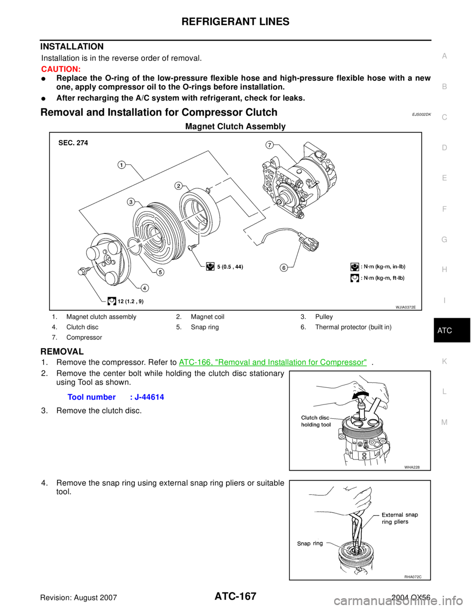
Removal and Installation for Compressor ClutchEJS002DK
Magnet Clutch Assembly
REMOVAL
1. Remove the compressor. Refer to ATC-166, "Removal and Installation for Compressor" .
2. Remove the center bolt while holding the clutch disc stationary
using Tool as shown.
3. Remove the clutch disc.
4. Remove the snap ring using external snap ring pliers or suitable
tool.
WJIA0372E
1. Magnet clutch assembly 2. Magnet coil 3. Pulley
4. Clutch disc 5. Snap ring 6. Thermal protector (built in)
7. Compressor
Tool number : J-44614
WHA228
RHA072C