Page 2765 of 3371

PS-14
STEERING COLUMN
Revision: August 20072004 QX56
ASSEMBLY
�Assembly is in the reverse order of disassembly.
�Install new tamper resistant self-shear screws.
INSPECTION AFTER ASSEMBLY
When the steering wheel does not turn smoothly, check the steering column as follows:
1. Check the column bearings for damage or unevenness. Lubricate with recommended multi-purpose
grease. Replace the steering column as an assembly, if necessary.
2. Check the column tube for deformation or breakage. Replace the steering column as an assembly, if nec-
essary.
3. If the vehicle has been involved in a collision, or if noise and rat-
tles are heard during a turn, check the length "L" of the column.
If out of specification, replace the steering column as an assem-
bly.
4. Check for proper lubrication, apply grease as necessary.
5. Check for wear around the seal edges, replace the steering col-
umn as an assembly as necessary.
6. Check for corrosion or pitting around the seal sliding area.
7. After installing the steering column, check the tilt mechanism for
proper operation.
CAUTION:
�Replace the column if it is depleted of grease, worn, dam-
aged, or if any scratches or coating separation is present
on the shaft seal area.
�During lower joint detachment, insert a tool into the yoke
groove to prevent gouging damage.
WGIA0009E
Steering column length "L" : 610 mm (24.02 in)
WGIA0080E
Tilt mechanism range
(Manual tilt): 3° per notch at 5 stops
WGIA0026E
Page 2766 of 3371
POWER STEERING GEAR AND LINKAGE
PS-15
C
D
E
F
H
I
J
K
L
MA
B
PS
Revision: August 20072004 QX56
POWER STEERING GEAR AND LINKAGEPFP:49001
Removal and InstallationEG S00 0M U
CAUTION:
Spiral cable may snap due to steering operation if steering column is separated from steering gear
assembly. Therefore secure steering wheel to avoid turning.
REMOVAL
1. Turn wheels to the straight-ahead position.
2. Remove tires from vehicle using power tool.
3. Remove undercover using power tool.
4. On 4WD models, remove front final drive, then support drive shafts with wire. Refer to FFD-12, "
Removal
and Installation" .
5. Make sure slit of lower joint fits with the projection on rear cover
cap, while checking that mark on steering gear assembly aligns
with mark on rear cover cap.
6. Remove cotter pin at steering outer socket and discard, then loosen mounting nut.
1. Cotter pin 2. Mounting bracket 3. Bushing
4. Washer 5. Steering gear assembly 6. Mounting insulator
WGIA0092E
SST 4 91 C
Page 2767 of 3371

PS-16
POWER STEERING GEAR AND LINKAGE
Revision: August 20072004 QX56
7. Remove steering outer socket from steering knuckle using Tool.
Be careful not to damage ball joint boot.
CAUTION:
Temporarily tighten mounting nut to prevent damage to
threads and to prevent Tool from coming off.
8. On 2WD models, remove stabilizer bar mounting bolts and reposition stabilizer bar. Refer to FSU-12,
"STABILIZER BAR" .
9. Remove oil piping (high pressure side and low pressure side)
from steering gear assembly, then drain fluid from piping.
10. Remove lower joint mounting bolt of lower shaft.
11. Remove mounting bolts and nuts of steering gear assembly
using power tool, and then remove steering gear assembly from
vehicle.
INSTALLATION
Installation is in the reverse order of removal.
�After removing/installing or replacing steering components, check wheel alignment. Refer to FSU-6,
"Front Wheel Alignment" .
�After adjusting wheel alignment, adjust neutral position of steering angle sensor. Refer to BRC-62,
"Adjustment of Steering Angle Sensor Neutral Position" . Tool number : HT72520000 (J-25730-A)
SDIA1434E
LGIA0032E
LGIA0029E
LGIA0024E
Page 2768 of 3371
POWER STEERING GEAR AND LINKAGE
PS-17
C
D
E
F
H
I
J
K
L
MA
B
PS
Revision: August 20072004 QX56
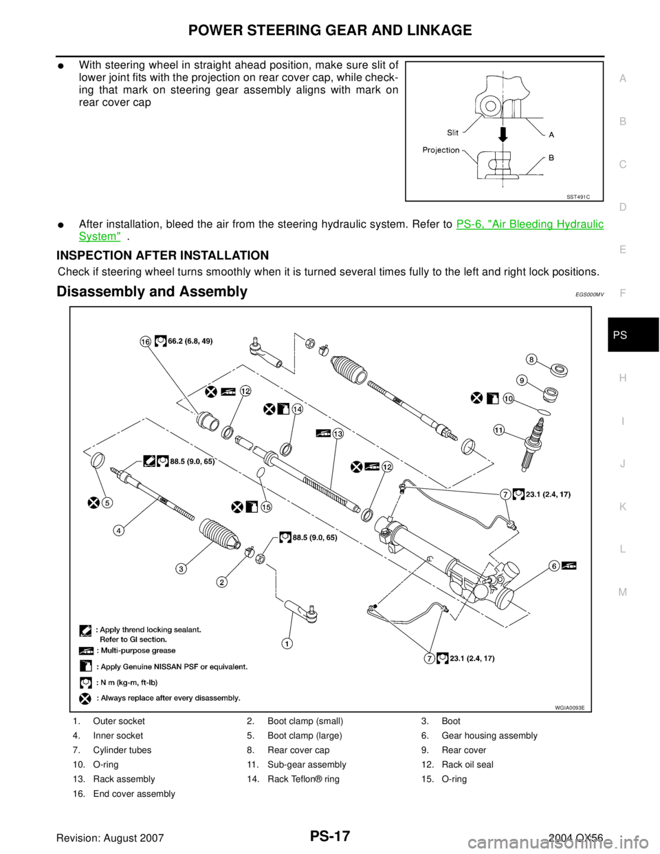
�With steering wheel in straight ahead position, make sure slit of
lower joint fits with the projection on rear cover cap, while check-
ing that mark on steering gear assembly aligns with mark on
rear cover cap
�After installation, bleed the air from the steering hydraulic system. Refer to PS-6, "Air Bleeding Hydraulic
System" .
INSPECTION AFTER INSTALLATION
Check if steering wheel turns smoothly when it is turned several times fully to the left and right lock positions.
Disassembly and AssemblyEGS000MV
SST 4 91 C
1. Outer socket 2. Boot clamp (small) 3. Boot
4. Inner socket 5. Boot clamp (large) 6. Gear housing assembly
7. Cylinder tubes 8. Rear cover cap 9. Rear cover
10. O-ring 11. Sub-gear assembly 12. Rack oil seal
13. Rack assembly 14. Rack Teflon® ring 15. O-ring
16. End cover assembly
WGIA0093E
Page 2784 of 3371
SERVICE DATA AND SPECIFICATIONS (SDS)
PS-33
C
D
E
F
H
I
J
K
L
MA
B
PS
Revision: August 20072004 QX56
SERVICE DATA AND SPECIFICATIONS (SDS)PFP:00030
Steering WheelEGS000NE
Steering ColumnEGS000NG
Inspection After Assembly
Unit: mm (in)
Inspection After Removal
Unit: mm (in) End play of the axial direction for steering wheel 0 mm (0 in)
Steering wheel play on the outer circumference 0 − 35 mm (0 − 1.38 in)
Steering wheel turning force 39 N (4 kg-f, 9 lb-f) or less
Steering column length “L”610 (24.02)
WGIA0080E
Steering column length “L2”262 (10.31)
Steering column length “L1” 158 (6.22)
SGIA0475E
Page 2788 of 3371

RAX-1
REAR AXLE
D DRIVELINE/AXLE
CONTENTS
C
E
F
G
H
I
J
K
L
M
SECTION RAX
A
B
RAX
Revision: August 20072004 QX56 PRECAUTIONS .......................................................... 2
Caution ..................................................................... 2
PREPARATION ........................................................... 3
Special Service Tools (SST) ..................................... 3
Commercial Service Tools ........................................ 3
NOISE, VIBRATION, AND HARSHNESS (NVH)
TROUBLESHOOTING ................................................ 4
NVH Troubleshooting Chart ..................................... 4
WHEEL HUB .............................................................. 5
On-Vehicle Inspection and Service .......................... 5
WHEEL BEARING INSPECTION ......................... 5
Removal and Installation .......................................... 5
REMOVAL ............................................................. 5
INSTALLATION ..................................................... 6REAR DRIVE SHAFT ................................................. 7
Components ............................................................. 7
Removal and Installation .......................................... 7
REMOVAL ............................................................. 7
INSPECTION AFTER REMOVAL ......................... 8
INSTALLATION ..................................................... 8
Disassembly and Assembly ...................................... 8
DISASSEMBLY ..................................................... 9
INSPECTION AFTER DISASSEMBLY ................ 10
ASSEMBLY ......................................................... 10
SERVICE DATA AND SPECIFICATIONS (SDS) ...... 14
Wheel Bearing ........................................................ 14
Drive Shaft .............................................................. 14
Page 2791 of 3371
 TROUBLESHOOTING
Revision: August 20072004 QX56
NOISE, VIBRATION, AND HARSHNESS (NVH) TROUBLESHOOTINGPFP:00003
NVH Troubleshooting ChartEDS001AS
Use chart be")
RAX-4
NOISE, VIBRATION, AND HARSHNESS (NVH) TROUBLESHOOTING
Revision: August 20072004 QX56
NOISE, VIBRATION, AND HARSHNESS (NVH) TROUBLESHOOTINGPFP:00003
NVH Troubleshooting ChartEDS001AS
Use chart below to help you find the cause of the symptom. If necessary, repair or replace these parts.
×: ApplicableReference page
—
RAX-8—
RAX-5—
RFD-5, "
NVH Troubleshooting Chart
"
FAX -4, "
NVH Troubleshooting Chart
" (FAX), FSU-4, "
NVH Troubleshooting Chart
" (FSU)
RSU-5, "
NVH Troubleshooting Chart
"
WT-3, "
NVH Troubleshooting Chart
"
WT-3, "
NVH Troubleshooting Chart
"
PR-3, "
NVH Troubleshooting Chart
"
BR-5, "
NVH Troubleshooting Chart
"
PS-5, "
NVH Troubleshooting Chart
"
Possible cause and SUSPECTED PARTS
Excessive joint angle
Joint sliding resistance
Imbalance
Improper installation, looseness
Parts interference
DIFFERENTIAL
FRONT AXLE AND FRONT SUSPENSION
REAR SUSPENSION
TIRES
ROAD WHEEL
PROPELLER SHAFT
BRAKES
STEERING
SymptomNoise×× ×× ×× ×××××
Shake× × ×× × ×××××
Vibration×× ×× × × × ×
Shimmy×× ×××××
Shudder× × ×× ××
Poor quality ride or handling×× ×× ×× ×
Page 2792 of 3371

WHEEL HUB
RAX-5
C
E
F
G
H
I
J
K
L
MA
B
RAX
Revision: August 20072004 QX56
WHEEL HUBPFP:43202
On-Vehicle Inspection and ServiceEDS001AT
Inspect the components for any looseness or back lash. Inspect each component for any excessive wear or
damage. Replace any components as necessary.
WHEEL BEARING INSPECTION
�Move the wheel hub and bearing assembly in the axial direction by hand to check the axial end play.
Check that the axial end play is with specification. Replace the wheel hub and bearing assembly as nec-
essary.
�Rotate the wheel hub and bearing assembly to check that there are no unusual noises or other abnormal
conditions. Replace the wheel hub and bearing assembly as necessary.
Removal and InstallationEDS001AU
Rear Wheel Hub and Bearing Assembly
NOTE:
The rear ABS sensor is routed through the back of the rear backing plate and into the side of the wheel hub
and bearing assembly. It is necessary to remove the wheel hub and bearing assembly to remove the rear ABS
sensor.
REMOVAL
1. Remove the wheel and tire using power tool.
2. Remove the rear brake caliper, without disconnecting the hydraulic hose, using power tool. Reposition the
rear brake caliper aside using suitable wire. Refer to BR-28, "
Removal and Installation of Brake Caliper
Assembly and Disc Rotor" .
NOTE:
�Do not depress the brake pedal while the brake caliper is removed.
3. Remove the rear disc rotor.Axial end play : 0 mm (0 in)
WDIA0300E
1. Back plate 2. Rear ABS sensor 3. Wheel hub and bearing assembly
4. Wheel stud 5. Rear disc rotor 6. Cotter pin
⇐: Vehicle front


PS-33
C
D
E
F
H
I
J
K
L
MA
B
PS
Revision: August 20072004 QX56
SERVICE DATA AND SPECIFICATIONS (SDS)PFP:00030
Steering WheelEGS000NE
Steering ColumnEGS000NG
Inspe")