Page 1963 of 3371
EM-80Revision: August 2007
CYLINDER BLOCK
2004 QX56
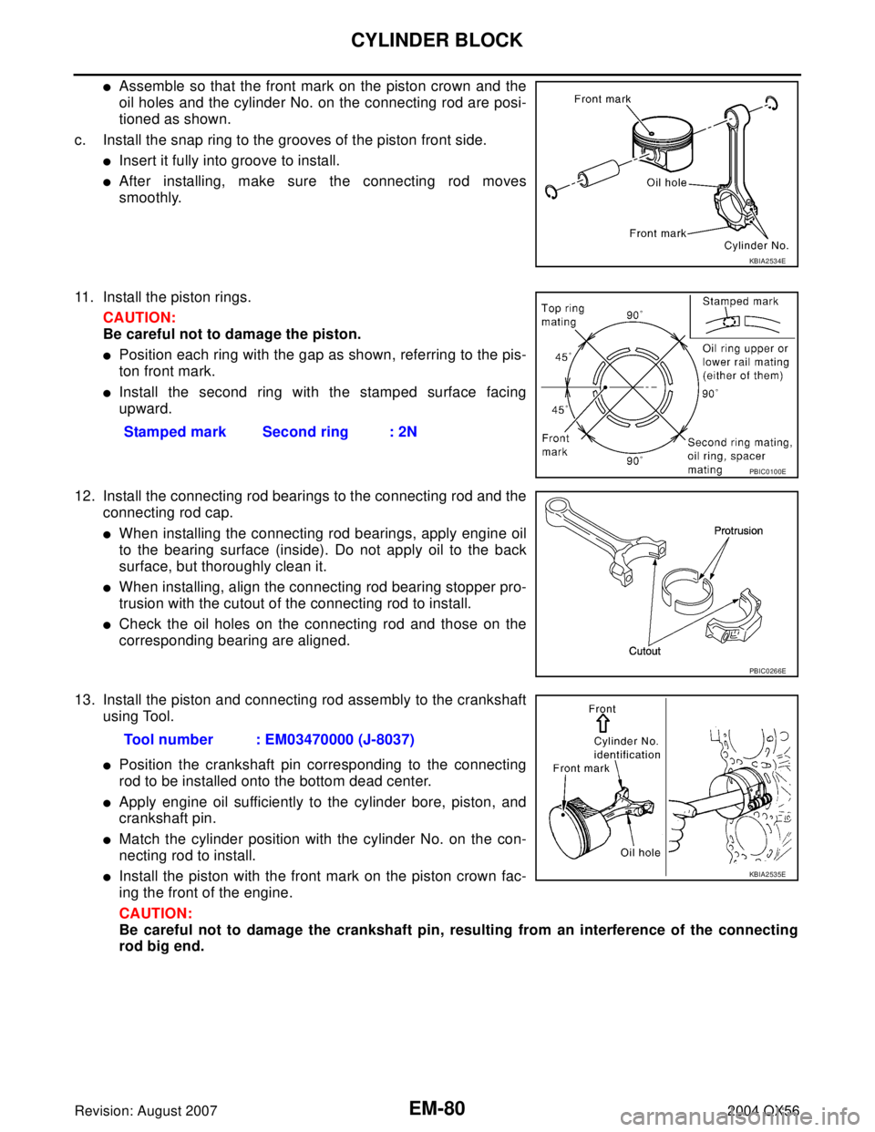
�Assemble so that the front mark on the piston crown and the
oil holes and the cylinder No. on the connecting rod are posi-
tioned as shown.
c. Install the snap ring to the grooves of the piston front side.
�Insert it fully into groove to install.
�After installing, make sure the connecting rod moves
smoothly.
11. Install the piston rings.
CAUTION:
Be careful not to damage the piston.
�Position each ring with the gap as shown, referring to the pis-
ton front mark.
�Install the second ring with the stamped surface facing
upward.
12. Install the connecting rod bearings to the connecting rod and the
connecting rod cap.
�When installing the connecting rod bearings, apply engine oil
to the bearing surface (inside). Do not apply oil to the back
surface, but thoroughly clean it.
�When installing, align the connecting rod bearing stopper pro-
trusion with the cutout of the connecting rod to install.
�Check the oil holes on the connecting rod and those on the
corresponding bearing are aligned.
13. Install the piston and connecting rod assembly to the crankshaft
using Tool.
�Position the crankshaft pin corresponding to the connecting
rod to be installed onto the bottom dead center.
�Apply engine oil sufficiently to the cylinder bore, piston, and
crankshaft pin.
�Match the cylinder position with the cylinder No. on the con-
necting rod to install.
�Install the piston with the front mark on the piston crown fac-
ing the front of the engine.
CAUTION:
Be careful not to damage the crankshaft pin, resulting from an interference of the connecting
rod big end.
KBIA2534E
Stamped mark Second ring : 2N
PBIC0100E
PBIC0266E
Tool number : EM03470000 (J-8037)
KBIA2535E
Page 1964 of 3371
CYLINDER BLOCK
EM-81
C
D
E
F
G
H
I
J
K
L
MA
EM
Revision: August 20072004 QX56
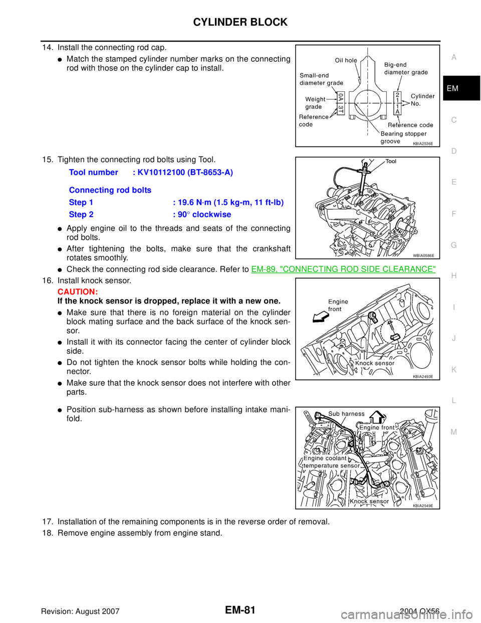
14. Install the connecting rod cap.
�Match the stamped cylinder number marks on the connecting
rod with those on the cylinder cap to install.
15. Tighten the connecting rod bolts using Tool.
�Apply engine oil to the threads and seats of the connecting
rod bolts.
�After tightening the bolts, make sure that the crankshaft
rotates smoothly.
�Check the connecting rod side clearance. Refer to EM-89, "CONNECTING ROD SIDE CLEARANCE"
16. Install knock sensor.
CAUTION:
If the knock sensor is dropped, replace it with a new one.
�Make sure that there is no foreign material on the cylinder
block mating surface and the back surface of the knock sen-
sor.
�Install it with its connector facing the center of cylinder block
side.
�Do not tighten the knock sensor bolts while holding the con-
nector.
�Make sure that the knock sensor does not interfere with other
parts.
�Position sub-harness as shown before installing intake mani-
fold.
17. Installation of the remaining components is in the reverse order of removal.
18. Remove engine assembly from engine stand.
KBIA2536E
Tool number : KV10112100 (BT-8653-A)
Connecting rod bolts
Step 1 : 19.6 N·m (1.5 kg-m, 11 ft-lb)
Step 2 : 90° clockwise
WBIA0586E
KBIA2493E
KBIA2549E
Page 2004 of 3371
DRIVE SHAFT
FAX-7
C
E
F
G
H
I
J
K
L
MA
B
FA X
Revision: August 20072004 QX56
DRIVE SHAFTPFP:39100
Removal and InstallationEDS001B5
REMOVAL
1. Remove wheel and tire using power tool.
2. Remove engine under cover using power tool.
3. Remove wheel sensor harness from mount on knuckle.
CAUTION:
Do not pull on wheel sensor harness.
4. Without disassembling the hydraulic lines, remove brake caliper using power tool. Reposition it aside with
wire. Refer to BR-22, "
Removal and Installation of Brake Caliper and Disc Rotor" .
NOTE:
Avoid depressing brake pedal while brake caliper is removed.
5. Remove coil spring and shock absorber assembly using power tool. Refer to FSU-10, "
Removal and
Installation" .
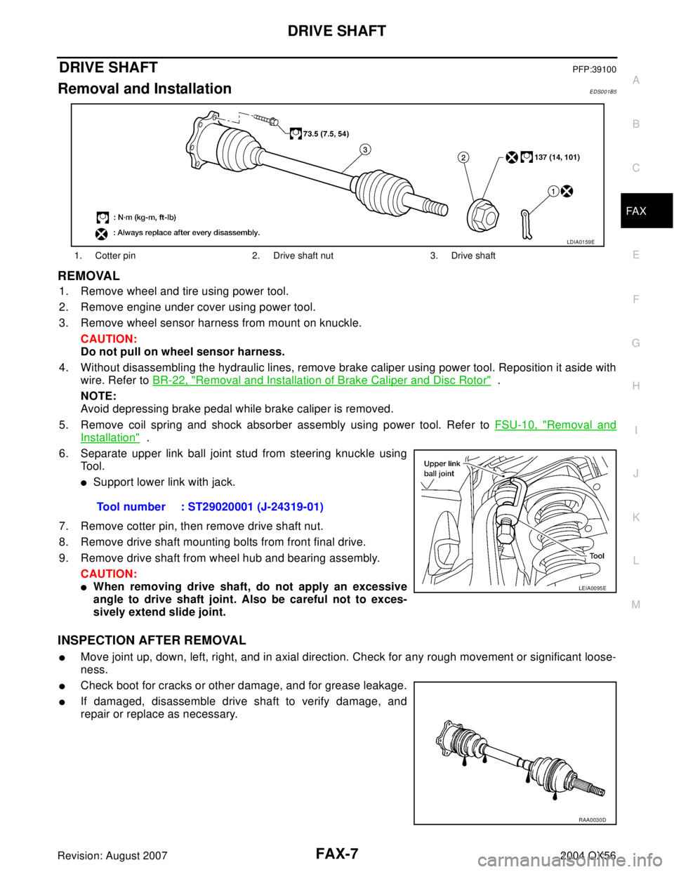
6. Separate upper link ball joint stud from steering knuckle using
Tool.
�Support lower link with jack.
7. Remove cotter pin, then remove drive shaft nut.
8. Remove drive shaft mounting bolts from front final drive.
9. Remove drive shaft from wheel hub and bearing assembly.
CAUTION:
�When removing drive shaft, do not apply an excessive
angle to drive shaft joint. Also be careful not to exces-
sively extend slide joint.
INSPECTION AFTER REMOVAL
�Move joint up, down, left, right, and in axial direction. Check for any rough movement or significant loose-
ness.
�Check boot for cracks or other damage, and for grease leakage.
�If damaged, disassemble drive shaft to verify damage, and
repair or replace as necessary.
1. Cotter pin 2. Drive shaft nut 3. Drive shaft
LDIA0159E
Tool number : ST29020001 (J-24319-01)
LEIA0095E
RAA0030D
Page 2014 of 3371
PRECAUTIONS
FFD-3
C
E
F
G
H
I
J
K
L
MA
B
FFD
Revision: August 20072004 QX56
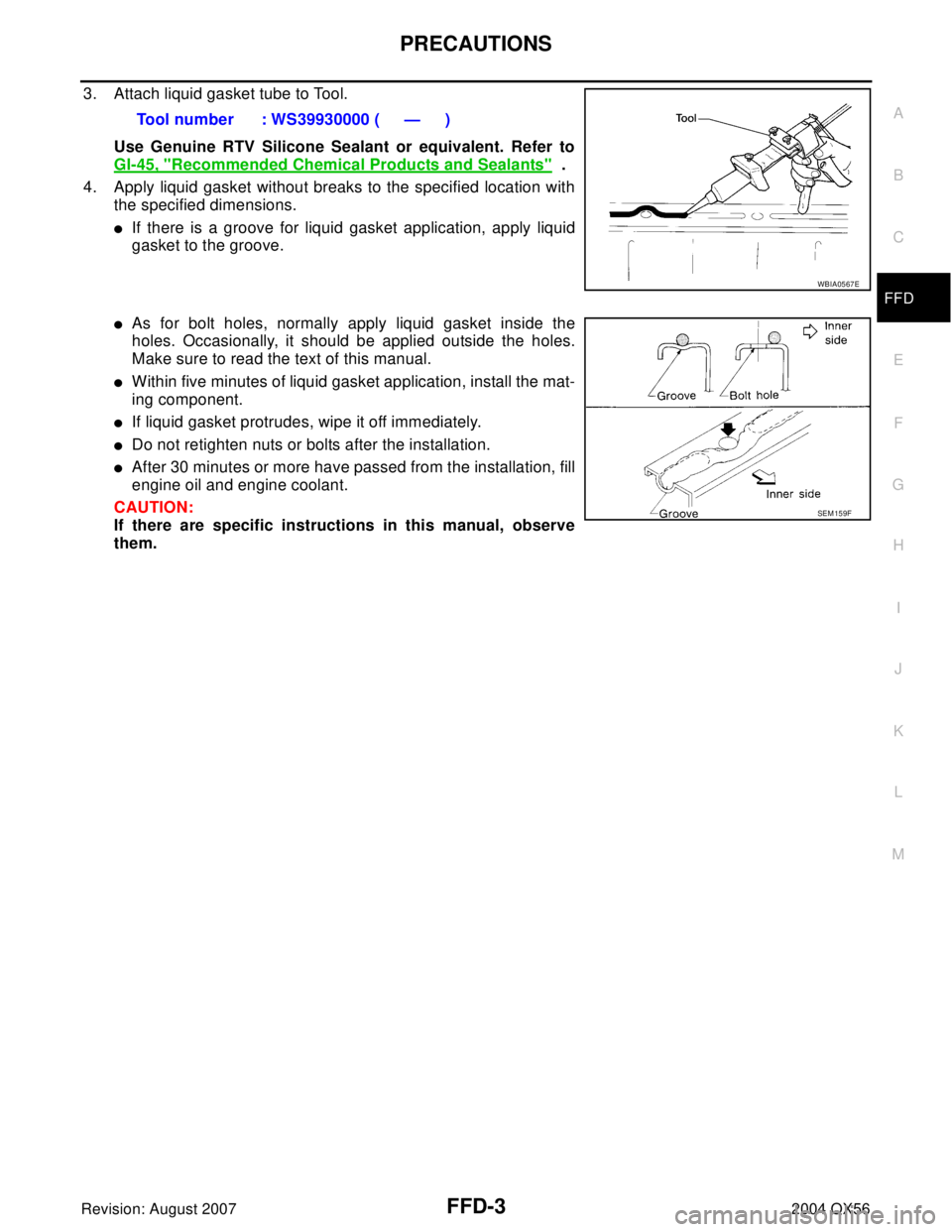
3. Attach liquid gasket tube to Tool.
Use Genuine RTV Silicone Sealant or equivalent. Refer to
GI-45, "
Recommended Chemical Products and Sealants" .
4. Apply liquid gasket without breaks to the specified location with
the specified dimensions.
�If there is a groove for liquid gasket application, apply liquid
gasket to the groove.
�As for bolt holes, normally apply liquid gasket inside the
holes. Occasionally, it should be applied outside the holes.
Make sure to read the text of this manual.
�Within five minutes of liquid gasket application, install the mat-
ing component.
�If liquid gasket protrudes, wipe it off immediately.
�Do not retighten nuts or bolts after the installation.
�After 30 minutes or more have passed from the installation, fill
engine oil and engine coolant.
CAUTION:
If there are specific instructions in this manual, observe
them.Tool number : WS39930000 ( — )
WBIA0567E
SEM 15 9F
Page 2043 of 3371
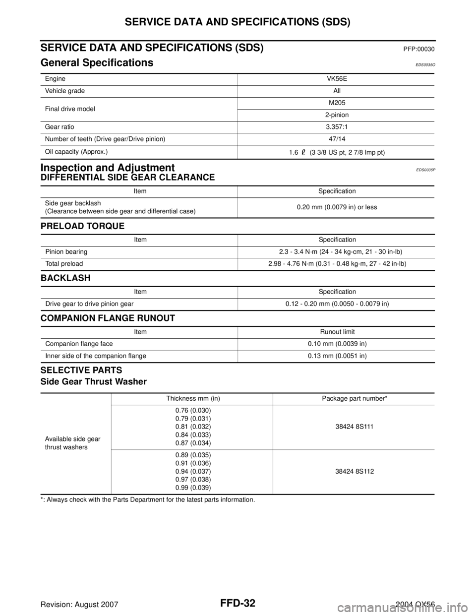
FFD-32
SERVICE DATA AND SPECIFICATIONS (SDS)
Revision: August 20072004 QX56
SERVICE DATA AND SPECIFICATIONS (SDS)PFP:00030
General SpecificationsEDS0035O
Inspection and AdjustmentEDS0035P
DIFFERENTIAL SIDE GEAR CLEARANCE
PRELOAD TORQUE
BACKLASH
COMPANION FLANGE RUNOUT
SELECTIVE PARTS
Side Gear Thrust Washer
*: Always check with the Parts Department for the latest parts information.EngineVK56E
Vehicle gradeAll
Final drive modelM205
2-pinion
Gear ratio3.357:1
Number of teeth (Drive gear/Drive pinion) 47/14
Oil capacity (Approx.)
1.6 (3 3/8 US pt, 2 7/8 lmp pt)
Item Specification
Side gear backlash
(Clearance between side gear and differential case)0.20 mm (0.0079 in) or less
Item Specification
Pinion bearing 2.3 - 3.4 N·m (24 - 34 kg-cm, 21 - 30 in-lb)
Total preload 2.98 - 4.76 N·m (0.31 - 0.48 kg-m, 27 - 42 in-lb)
Item Specification
Drive gear to drive pinion gear 0.12 - 0.20 mm (0.0050 - 0.0079 in)
Item Runout limit
Companion flange face 0.10 mm (0.0039 in)
Inner side of the companion flange 0.13 mm (0.0051 in)
Available side gear
thrust washersThickness mm (in) Package part number*
0.76 (0.030)
0.79 (0.031)
0.81 (0.032)
0.84 (0.033)
0.87 (0.034)38424 8S111
0.89 (0.035)
0.91 (0.036)
0.94 (0.037)
0.97 (0.038)
0.99 (0.039)38424 8S112
Page 2061 of 3371
FSU-2
PRECAUTIONS
Revision: August 20072004 QX56
PRECAUTIONSPFP:00001
PrecautionsEES0010D
�When installing the rubber bushings, the final tightening must be done under unladen condition and with
the tires on level ground. Oil will shorten the life of the rubber bushings, so wipe off any spilled oil immedi-
ately.
�Unladen condition means the fuel tank, engine coolant and lubricants are at the full specification. The
spare tire, jack, hand tools, and mats are in their designated positions.
�After installing suspension components, check the wheel alignment.
�Lock nuts are not reusable. Always use new lock nuts for installation. New lock nuts are pre-oiled, do not
apply any additional lubrication.
Page 2079 of 3371
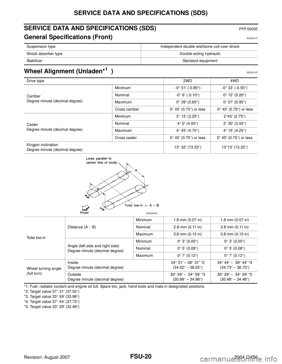
FSU-20
SERVICE DATA AND SPECIFICATIONS (SDS)
Revision: August 20072004 QX56
SERVICE DATA AND SPECIFICATIONS (SDS)PFP:00030
General Specifications (Front)EES0010T
Wheel Alignment (Unladen*1 )EES0012Y
*1: Fuel, radiator coolant and engine oil full. Spare tire, jack, hand tools and mats in designated positions.
*2: Target value 37° 31′ (37.52°)
*3: Target value 33° 59′ (33.98°)
*4: Target value 37° 44′ (37.73°)
*5: Target value 33° 29′ (33.48°) Suspension type Independent double wishbone coil over shock
Shock absorber type Double-acting hydraulic
StabilizerStandard equipment
Drive type2WD 4WD
Camber
Degree minute (decimal degree)Minimum -0° 51′ (-0.85°)-0° 33′ (-0.55°)
Nominal -0° 6′ (-0.10°)0° 12′ (0.20°)
Maximum 0° 39′ (0.65°)0° 57′ (0.95°)
Cross camber 0° 45′ (0.75°) or less 0° 45′ (0.75°) or less
Caster
Degree minute (decimal degree)Minimum 3° 15′ (3.25°)2°45′ (2.75°)
Nominal 4° 0′ (4.00°)3° 30′ (3.50°)
Maximum 4° 45′ (4.75°)4° 15′ (4.25°)
Cross caster 0° 45′ (0.75°) or less 0° 45′ (0.75°) or less
Kingpin inclination
Degree minute (decimal degree)13° 32′ (13.53°)13°13′ (13.22°)
Total toe-inDistance (A − B)Minimum 1.8 mm (0.07 in) 1.8 mm (0.07 in)
Nominal 2.8 mm (0.11 in) 2.8 mm (0.11 in)
Maximum 3.8 mm (0.15 in) 3.8 mm (0.15 in)
Angle (left side and right side)
Degree minute (decimal degree)Minimum 0° 3′ (0.05°)0° 3′ (0.05°)
Nominal 0° 5′ (0.08°)0° 5′ (0.08°)
Maximum 0° 7′ (0.12°)0° 7′ (0.12°)
Wheel turning angle
(full turn)Inside
Degree minute (decimal degree)34° 31′ – 38° 31′ *2
(34.52° – 38.52°)34° 44′ – 38° 44′ *4
(34.73° – 38.73°)
Outside
Degree minute (decimal degree)30° 59′ – 34° 59′ *3
(30.98° – 34.98°)30° 29′ – 34° 29′ *5
(30.48° – 34.48°)
SFA234AC
Page 2080 of 3371
SERVICE DATA AND SPECIFICATIONS (SDS)
FSU-21
C
D
F
G
H
I
J
K
L
MA
B
FSU
Revision: August 20072004 QX56
Ball JointEES0013H
*1 Measure at cotter pin hole
*2 Measure at groove
Wheelarch Height (Unladen*1 )EES0010W
Unit: mm (in)
*1: Fuel, radiator coolant and engine oil full. Spare tire, jack, hand tools and mats in designated positions.
*2: Confirm level using Consult-II, register 1103. Set rear wheel arch height to “0” if necessary.Swinging force “A”Upper ball joint 8.1 – 103.2 N (0.8 – 10.5 kg-f, 1.8 – 23.2 lb-f) *1
Lower ball joint 11.4 – 145.5 N (1.1 – 14.8 kg-f, 2.5 – 32.7 lb-f) *2
Turning torque “B” 0.5 - 6.4 N·m (0.05 - 0.65 kg-m, 4 - 57 in-lb)
Vertical end play “C”0 mm (0 in)
SFA858AWEIA0076E
Suspension type
Air leveling*2
Applied model 2WD 4WD
Front wheelarch height (Hf)913
(35.94)931
(36.65)
Rear wheelarch height (Hr)912
(35.91)932
(36.69)
LEIA0085E