Page 2201 of 3371
GW-66
POWER WINDOW SYSTEM
Revision: August 20072004 QX56
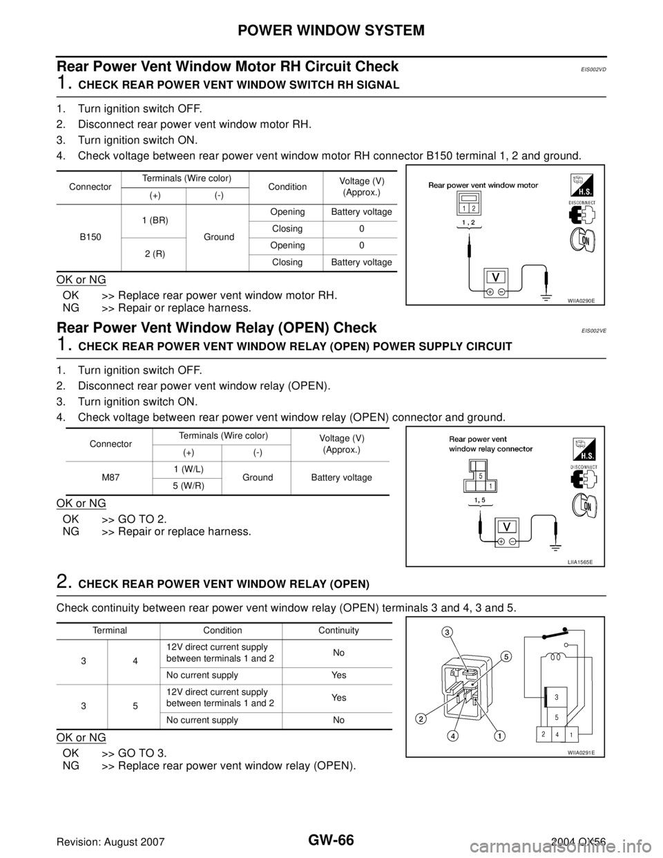
Rear Power Vent Window Motor RH Circuit CheckEIS002VD
1. CHECK REAR POWER VENT WINDOW SWITCH RH SIGNAL
1. Turn ignition switch OFF.
2. Disconnect rear power vent window motor RH.
3. Turn ignition switch ON.
4. Check voltage between rear power vent window motor RH connector B150 terminal 1, 2 and ground.
OK or NG
OK >> Replace rear power vent window motor RH.
NG >> Repair or replace harness.
Rear Power Vent Window Relay (OPEN) CheckEIS002VE
1. CHECK REAR POWER VENT WINDOW RELAY (OPEN) POWER SUPPLY CIRCUIT
1. Turn ignition switch OFF.
2. Disconnect rear power vent window relay (OPEN).
3. Turn ignition switch ON.
4. Check voltage between rear power vent window relay (OPEN) connector and ground.
OK or NG
OK >> GO TO 2.
NG >> Repair or replace harness.
2. CHECK REAR POWER VENT WINDOW RELAY (OPEN)
Check continuity between rear power vent window relay (OPEN) terminals 3 and 4, 3 and 5.
OK or NG
OK >> GO TO 3.
NG >> Replace rear power vent window relay (OPEN).
ConnectorTerminals (Wire color)
ConditionVoltage (V)
(Approx.)
(+) (-)
B1501 (BR)
GroundOpening Battery voltage
Closing 0
2 (R)Opening 0
Closing Battery voltage
WIIA0290E
ConnectorTerminals (Wire color)
Voltage (V)
(Approx.)
(+) (-)
M871 (W/L)
Ground Battery voltage
5 (W/R)
LIIA1565E
Terminal Condition Continuity
3412V direct current supply
between terminals 1 and 2No
No current supply Yes
3512V direct current supply
between terminals 1 and 2Ye s
No current supply No
WIIA0291E
Page 2202 of 3371
POWER WINDOW SYSTEM
GW-67
C
D
E
F
G
H
J
K
L
MA
B
GW
Revision: August 20072004 QX56
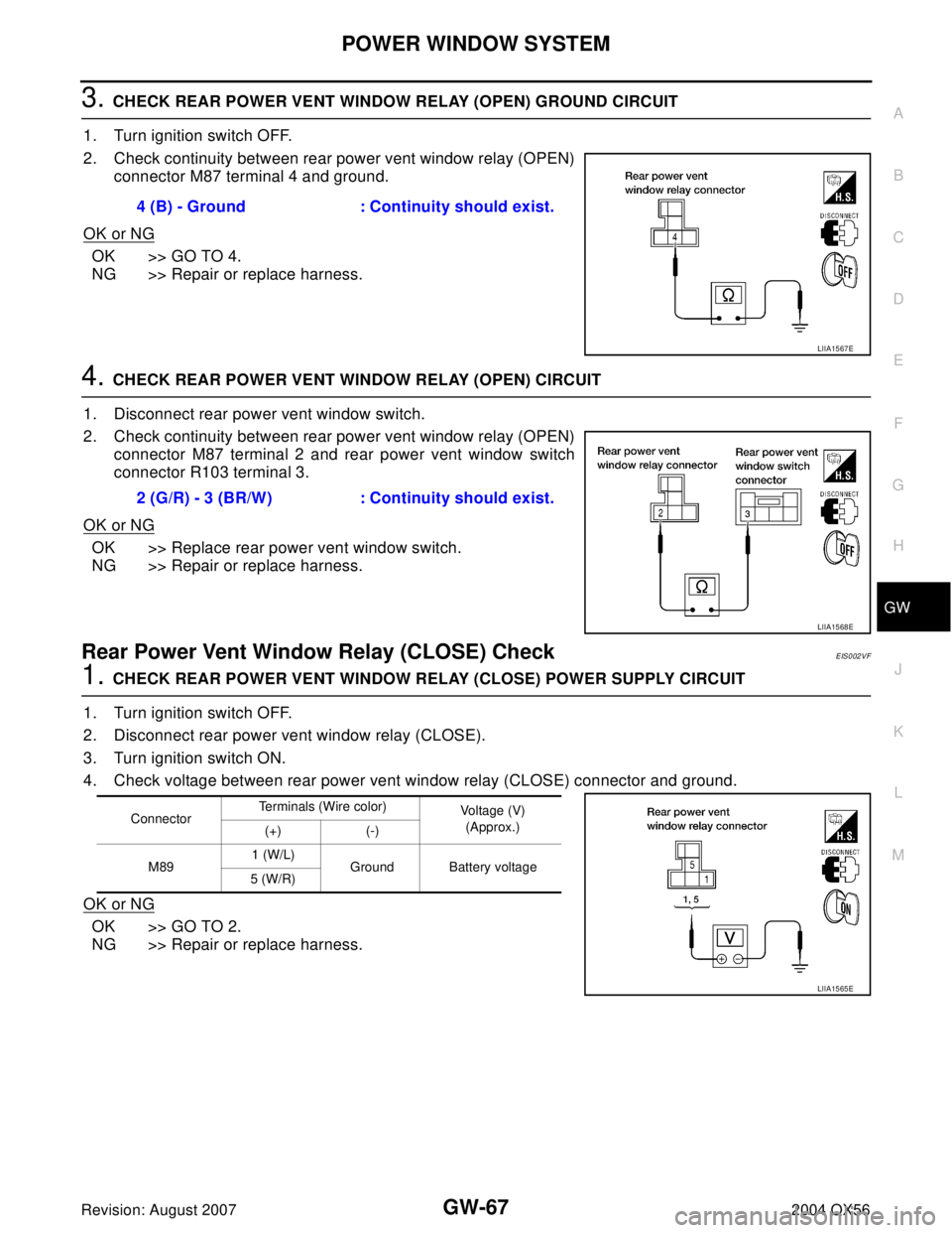
3. CHECK REAR POWER VENT WINDOW RELAY (OPEN) GROUND CIRCUIT
1. Turn ignition switch OFF.
2. Check continuity between rear power vent window relay (OPEN)
connector M87 terminal 4 and ground.
OK or NG
OK >> GO TO 4.
NG >> Repair or replace harness.
4. CHECK REAR POWER VENT WINDOW RELAY (OPEN) CIRCUIT
1. Disconnect rear power vent window switch.
2. Check continuity between rear power vent window relay (OPEN)
connector M87 terminal 2 and rear power vent window switch
connector R103 terminal 3.
OK or NG
OK >> Replace rear power vent window switch.
NG >> Repair or replace harness.
Rear Power Vent Window Relay (CLOSE) CheckEIS002VF
1. CHECK REAR POWER VENT WINDOW RELAY (CLOSE) POWER SUPPLY CIRCUIT
1. Turn ignition switch OFF.
2. Disconnect rear power vent window relay (CLOSE).
3. Turn ignition switch ON.
4. Check voltage between rear power vent window relay (CLOSE) connector and ground.
OK or NG
OK >> GO TO 2.
NG >> Repair or replace harness.4 (B) - Ground : Continuity should exist.
LIIA1567E
2 (G/R) - 3 (BR/W) : Continuity should exist.
LIIA1568E
ConnectorTerminals (Wire color)
Voltage (V)
(Approx.)
(+) (-)
M891 (W/L)
Ground Battery voltage
5 (W/R)
LIIA1565E
Page 2203 of 3371
GW-68
POWER WINDOW SYSTEM
Revision: August 20072004 QX56
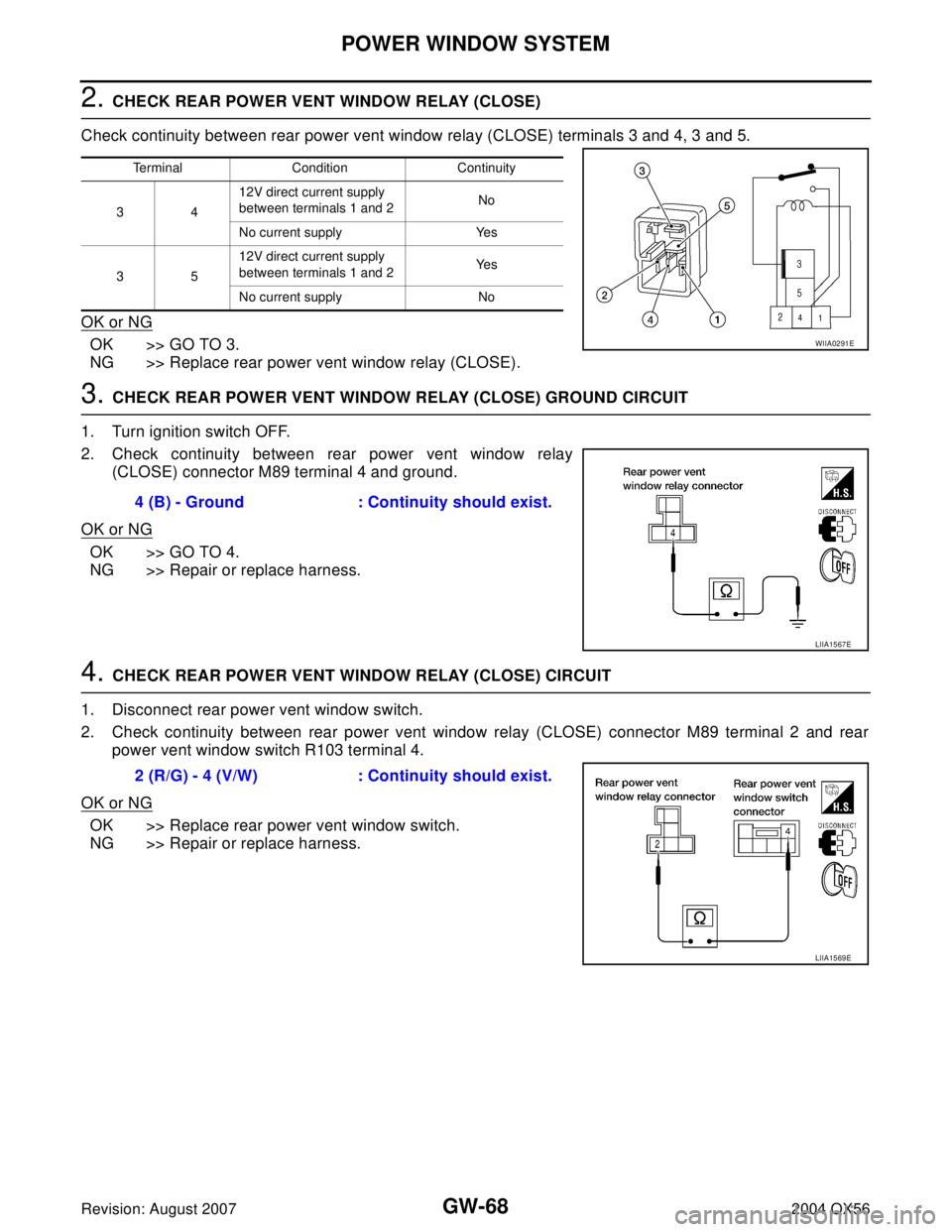
2. CHECK REAR POWER VENT WINDOW RELAY (CLOSE)
Check continuity between rear power vent window relay (CLOSE) terminals 3 and 4, 3 and 5.
OK or NG
OK >> GO TO 3.
NG >> Replace rear power vent window relay (CLOSE).
3. CHECK REAR POWER VENT WINDOW RELAY (CLOSE) GROUND CIRCUIT
1. Turn ignition switch OFF.
2. Check continuity between rear power vent window relay
(CLOSE) connector M89 terminal 4 and ground.
OK or NG
OK >> GO TO 4.
NG >> Repair or replace harness.
4. CHECK REAR POWER VENT WINDOW RELAY (CLOSE) CIRCUIT
1. Disconnect rear power vent window switch.
2. Check continuity between rear power vent window relay (CLOSE) connector M89 terminal 2 and rear
power vent window switch R103 terminal 4.
OK or NG
OK >> Replace rear power vent window switch.
NG >> Repair or replace harness.
Terminal Condition Continuity
3412V direct current supply
between terminals 1 and 2No
No current supply Yes
3512V direct current supply
between terminals 1 and 2Ye s
No current supply No
WIIA0291E
4 (B) - Ground : Continuity should exist.
LIIA1567E
2 (R/G) - 4 (V/W) : Continuity should exist.
LIIA1569E
Page 2214 of 3371

REAR WINDOW DEFOGGER
GW-79
C
D
E
F
G
H
J
K
L
MA
B
GW
Revision: August 20072004 QX56
System DescriptionEIS002VN
The rear window defogger system is controlled by BCM (body control module) and IPDM E/R (intelligent
power distribution module engine room).
The rear window defogger operates only for approximately 15 minutes.
Power is supplied at all times
�through 15A fuses (No. 43, 46, and 47, located in the IPDM E/R)
�to rear window defogger relay terminals 3 and 6 (located in the IPDM E/R)
�through 50A fusible link (letter f , located in the fuse and fusible link box)
�to BCM terminal 70.
With the ignition switch turned to ON or START position,
Power is supplied
�through ignition switch
�to rear window defogger relay (located in the IPDM E/R)
�through 10A fuse (No. 59, located in the fuse and relay box)
�to BCM terminal 38
�through 10A fuse [No. 8, located in the fuse block (J/B)]
�to front air control terminal 14.
Ground is supplied
�to BCM terminal 67
�to front air control terminal 1
�through body grounds M57, M61 and M79
�to IPDM E/R terminals 38 and 59
�through body grounds E9, E15 and E24.
When front air control (rear window defogger switch) is turned to ON,
Ground is supplied
�to BCM terminal 9
�through front air control terminal 11
�through front air control terminal 1
�through body grounds M57, M61 and M79.
Then rear window defogger switch is illuminated.
Then BCM recognizes that rear window defogger switch is turned to ON.
Then it sends rear window defogger switch signals to IPDM E/R and display control unit via DATA LINE (CAN-
H, CAN-L).
When display control unit receives rear window defogger switch signals, and displays on the screen.
When IPDM E/R receives rear window defogger switch signals,
Ground is supplied
�to rear window defogger relay (located in the IPDM E/R)
�through IPDM E/R terminal 38
�through IPDM E/R terminal 59
�through body grounds E9, E15 and E24.
Then rear window defogger relay is energized.
With power and ground supplied, rear window defogger filaments heat and defog the rear window.
When rear window defogger relay is turned to ON,
Power is supplied
�through heated mirror relay (located in the IPDM E/R)
�through IPDM E/R terminal 23
�to door mirror defogger (LH and RH) terminal 10.
Door mirror defogger (LH and RH) is grounded through body grounds M57, M61 and M79.
With power and ground supplied, rear window defogger filaments heat and defog the rear window and door
mirror defogger filaments heat and defog the mirror.
Page 2215 of 3371
GW-80
REAR WINDOW DEFOGGER
Revision: August 20072004 QX56
CAN Communication System DescriptionEIS002VO
Refer to LAN-5, "CAN COMMUNICATION" .
Page 2220 of 3371
REAR WINDOW DEFOGGER
GW-85
C
D
E
F
G
H
J
K
L
MA
B
GW
Revision: August 20072004 QX56
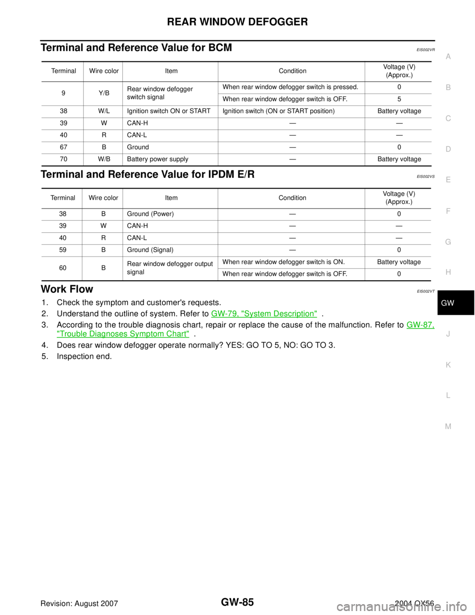
Terminal and Reference Value for BCMEIS002VR
Terminal and Reference Value for IPDM E/REIS002VS
Work FlowEIS002VT
1. Check the symptom and customer's requests.
2. Understand the outline of system. Refer to GW-79, "
System Description" .
3. According to the trouble diagnosis chart, repair or replace the cause of the malfunction. Refer to GW-87,
"Trouble Diagnoses Symptom Chart" .
4. Does rear window defogger operate normally? YES: GO TO 5, NO: GO TO 3.
5. Inspection end.
Terminal Wire color Item ConditionVoltage (V)
(Approx.)
9Y/BRear window defogger
switch signalWhen rear window defogger switch is pressed. 0
When rear window defogger switch is OFF. 5
38 W/L Ignition switch ON or START Ignition switch (ON or START position) Battery voltage
39 W CAN-H — —
40 R CAN-L — —
67 B Ground — 0
70 W/B Battery power supply — Battery voltage
Terminal Wire color Item ConditionVoltage (V)
(Approx.)
38 B Ground (Power) — 0
39 W CAN-H — —
40 R CAN-L — —
59 B Ground (Signal) — 0
60 BRear window defogger output
signalWhen rear window defogger switch is ON. Battery voltage
When rear window defogger switch is OFF. 0
Page 2222 of 3371
REAR WINDOW DEFOGGER
GW-87
C
D
E
F
G
H
J
K
L
MA
B
GW
Revision: August 20072004 QX56
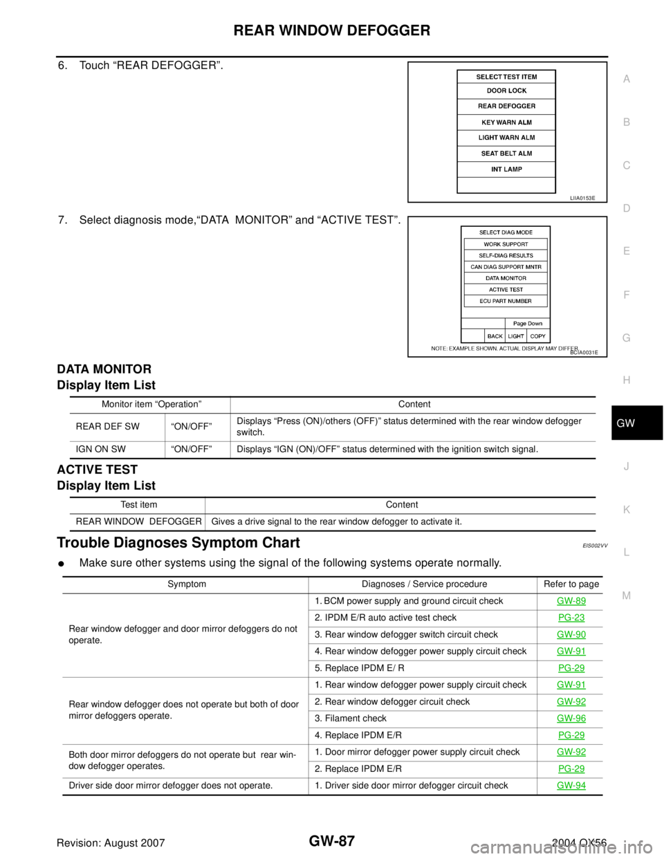
6. Touch “REAR DEFOGGER”.
7. Select diagnosis mode,“DATA MONITOR” and “ACTIVE TEST”.
DATA MONITOR
Display Item List
ACTIVE TEST
Display Item List
Trouble Diagnoses Symptom ChartEIS002VV
�Make sure other systems using the signal of the following systems operate normally.
LIIA0153E
BCIA0031E
Monitor item “Operation” Content
REAR DEF SW “ON/OFF”Displays “Press (ON)/others (OFF)” status determined with the rear window defogger
switch.
IGN ON SW “ON/OFF” Displays “IGN (ON)/OFF” status determined with the ignition switch signal.
Test item Content
REAR WINDOW DEFOGGER Gives a drive signal to the rear window defogger to activate it.
Symptom Diagnoses / Service procedure Refer to page
Rear window defogger and door mirror defoggers do not
operate.1. BCM power supply and ground circuit checkGW-89
2. IPDM E/R auto active test checkPG-23
3. Rear window defogger switch circuit checkGW-90
4. Rear window defogger power supply circuit checkGW-91
5. Replace IPDM E/ RPG-29
Rear window defogger does not operate but both of door
mirror defoggers operate.1. Rear window defogger power supply circuit checkGW-912. Rear window defogger circuit checkGW-92
3. Filament checkGW-96
4. Replace IPDM E/RPG-29
Both door mirror defoggers do not operate but rear win-
dow defogger operates.1. Door mirror defogger power supply circuit checkGW-92
2. Replace IPDM E/RPG-29
Driver side door mirror defogger does not operate. 1. Driver side door mirror defogger circuit checkGW-94
Page 2231 of 3371
GW-96
REAR WINDOW DEFOGGER
Revision: August 20072004 QX56
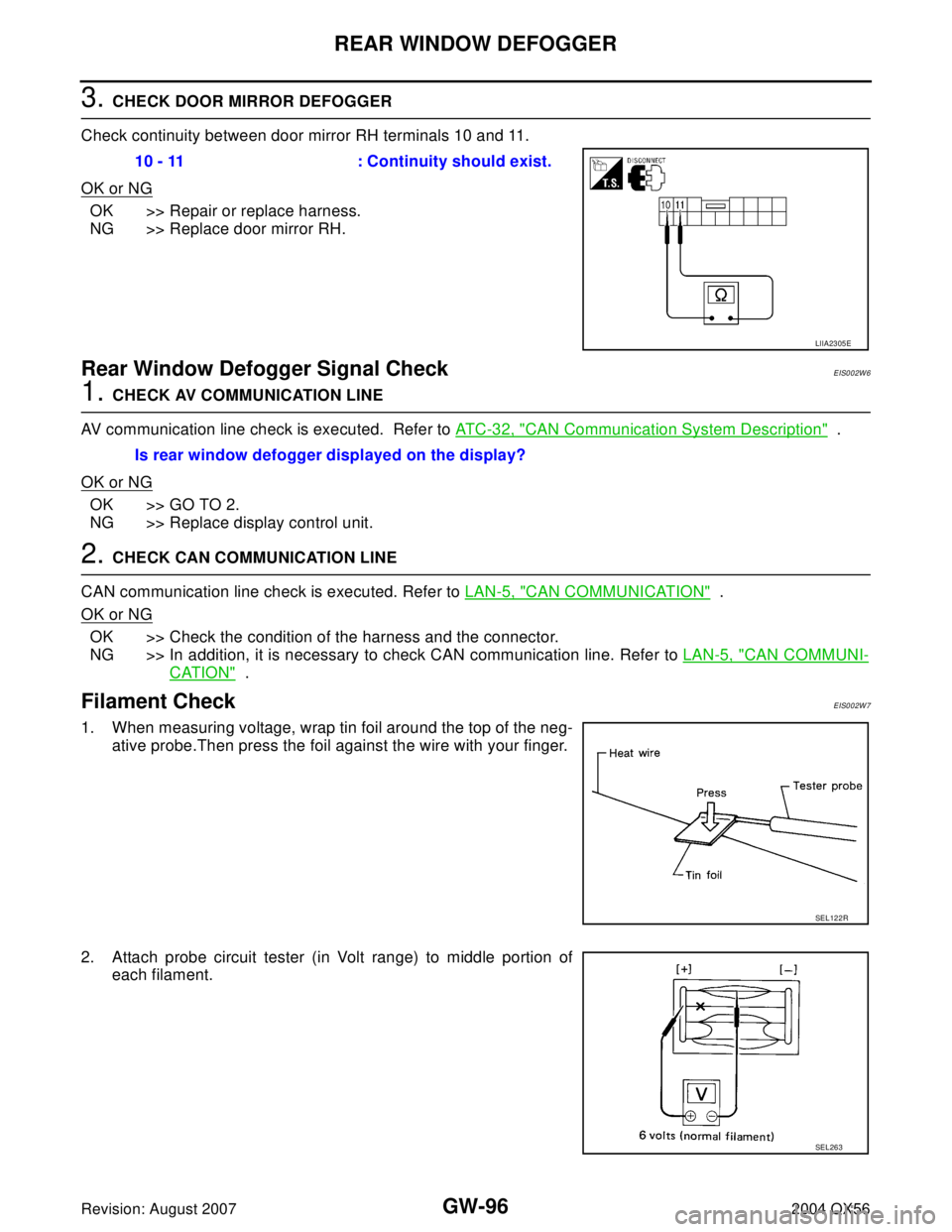
3. CHECK DOOR MIRROR DEFOGGER
Check continuity between door mirror RH terminals 10 and 11.
OK or NG
OK >> Repair or replace harness.
NG >> Replace door mirror RH.
Rear Window Defogger Signal CheckEIS002W6
1. CHECK AV COMMUNICATION LINE
AV communication line check is executed. Refer to AT C - 3 2 , "
CAN Communication System Description" .
OK or NG
OK >> GO TO 2.
NG >> Replace display control unit.
2. CHECK CAN COMMUNICATION LINE
CAN communication line check is executed. Refer to LAN-5, "
CAN COMMUNICATION" .
OK or NG
OK >> Check the condition of the harness and the connector.
NG >> In addition, it is necessary to check CAN communication line. Refer to LAN-5, "
CAN COMMUNI-
CATION" .
Filament CheckEIS002W7
1. When measuring voltage, wrap tin foil around the top of the neg-
ative probe.Then press the foil against the wire with your finger.
2. Attach probe circuit tester (in Volt range) to middle portion of
each filament.10 - 11 : Continuity should exist.
LIIA2305E
Is rear window defogger displayed on the display?
SEL122R
SEL263