Page 1532 of 3371
DTC P0500 VSS
EC-341
C
D
E
F
G
H
I
J
K
L
MA
EC
Revision: August 20072004 QX56
2. Start engine.
3. Read vehicle speed sensor signal in MODE 1 with GST.
The vehicle speed sensor on GST should be able to exceed 10 km/h (6 MPH) when rotating wheels with
suitable gear position.
4. If NG, go to EC-341, "
Diagnostic Procedure" .
Diagnostic ProcedureUBS00H6G
1. CHECK DTC WITH ABS ACTUATOR AND ELECTRIC UNIT (CONTROL UNIT)
Refer to BRC-11, "
TROUBLE DIAGNOSIS" .
OK or NG
OK >> GO TO 2.
NG >> Repair or replace.
2. CHECK DTC WITH COMBINATION METER
Refer to DI-5, "
COMBINATION METERS" .
>>INSPECTION END
Page 1599 of 3371
EC-408Revision: August 2007
DTC P1211 TCS CONTROL UNIT
2004 QX56
DTC P1211 TCS CONTROL UNITPFP:47850
DescriptionUBS00H8L
The malfunction information related to TCS is transferred through the CAN communication line from “ABS
actuator and electric unit (control unit)” to ECM.
Be sure to erase the malfunction information such as DTC not only for “ABS actuator and electric unit
(control unit)” but also for ECM after TCS related repair.
On Board Diagnosis LogicUBS00H8M
Freeze frame data is not stored in the ECM for this self-diagnosis.
The MIL will not light up for this self-diagnosis.
DTC Confirmation ProcedureUBS00H8N
TESTING CONDITION:
Before performing the following procedure, confirm that battery voltage is more than 10.5V at idle.
WITH CONSULT-II
1. Turn ignition switch ON.
2. Select “DATA MONITOR” mode with CONSULT-II.
3. Start engine and let it idle for at least 60 seconds.
4. If 1st trip DTC is detected, go to EC-408, "
Diagnostic Procedure"
.
WITH GST
Follow the procedure “WITH CONSULT-II” above.
Diagnostic ProcedureUBS00H8O
Go to BRC-11, "TROUBLE DIAGNOSIS" .
DTC No. Trouble diagnosis name DTC detecting condition Possible cause
P1211
1211TCS control unitECM receives a malfunction information from
“ABS actuator electric unit (control unit)”
�ABS actuator and electric unit (control
unit)
�TCS related parts
SEF 0 58 Y
Page 1600 of 3371
DTC P1212 TCS COMMUNICATION LINE
EC-409
C
D
E
F
G
H
I
J
K
L
MA
EC
Revision: August 20072004 QX56
DTC P1212 TCS COMMUNICATION LINEPFP:47850
DescriptionUBS00H8P
NOTE:
If DTC P1212 is displayed with DTC U1000 or U1001, first perform the trouble diagnosis for DTC U1000,
U1001. Refer to EC-135, "
DTC U1000, U1001 CAN COMMUNICATION LINE" .
This CAN communication line is used to control the smooth engine operation during the TCS operation. Pulse
signals are exchanged between ECM and “ABS actuator and electric unit (control unit)”.
Be sure to erase the malfunction information such as DTC not only for “ABS actuator and electric unit
(control unit)” but also for ECM after TCS related repair.
On Board Diagnosis LogicUBS00H8Q
Freeze frame data is not stored in the ECM for this self-diagnosis.
The MIL will not light up for this self-diagnosis.
DTC Confirmation ProcedureUBS00H8R
TESTING CONDITION:
Before performing the following procedure, confirm that battery voltage is more than 10.5V at idle.
WITH CONSULT-II
1. Turn ignition switch ON.
2. Select “DATA MONITOR” mode with CONSULT-II.
3. Start engine and let it idle for at least 10 seconds.
4. If a 1st trip DTC is detected, go to EC-409, "
Diagnostic Proce-
dure" .
WITH GST
Follow the procedure “WITH CONSULT-II” above.
Diagnostic ProcedureUBS00H8S
1. CHECK ABS ACTUATOR AND ELECTRIC UNIT (CONTROL UNIT) FUNCTION
Refer to BRC-11, "
TROUBLE DIAGNOSIS" .
>>INSPECTION END
DTC No. Trouble diagnosis name DTC detecting condition Possible cause
P1212
1212TCS communication
lineECM can not receive the information
from “ABS actuator and electric unit (con-
trol unit)” continuously.
�Harness or connectors
(The CAN communication line is open or
shorted.)
�ABS actuator and electric unit (control unit)
�Dead (Weak) battery
SEF 0 58 Y
Page 1733 of 3371
EC-542Revision: August 2007
DTC P1574 ICC VEHICLE SPEED SENSOR
2004 QX56
DTC P1574 ICC VEHICLE SPEED SENSORPFP:31036
Component DescriptionUBS00HZ6
The ECM receives two vehicle speed signals via CAN communication line. One is sent from “unified meter and
A/C amp.”, and the other is from TCM (Transmission control module). The ECM uses these signals for ICC
control. Refer to ACS-6, "
DESCRIPTION" for ICC functions.
On Board Diagnosis LogicUBS00HZ7
�This self-diagnosis has the one trip detection logic.
�The MIL will not light up for this self-diagnosis.
NOTE:
�If DTC P1574 is displayed with DTC U1000, U1001, first perform the trouble diagnosis for DTC
U1000, U1001. Refer to EC-135, "
DTC U1000, U1001 CAN COMMUNICATION LINE" .
�If DTC P1574 is displayed with DTC P0500, first perform the trouble diagnosis for DTC P0500.
Refer to EC-340, "
DTC P0500 VSS" .
�If DTC P1574 is displayed with DTC P0605, first perform the trouble diagnosis for DTC P0605.
Refer to EC-351, "
DTC P0605 ECM" .
DTC Confirmation ProcedureUBS00HZ8
CAUTION:
Always drive vehicle at a safe speed.
NOTE:
If DTC Confirmation Procedure has been previously conducted, always turn ignition switch OFF and wait at
least 10 seconds before conducting the next test.
TESTING CONDITION:
Step 3 may be conducted with the drive wheels lifted in the shop or by driving the vehicle. If a road test
is expected to be easier, it is unnecessary to lift the vehicle.
WITH CONSULT-II
1. Start engine.
2. Select “DATA MONITOR” mode with CONSULT-II.
3. Drive the vehicle at more than 40 km/h (25MPH).
4. If DTC is detected, go to EC-543, "
Diagnostic Procedure" .
WITH GST
Follow the procedure “WITH CONSULT-II” above.
DTC No. Trouble Diagnosis Name DTC Detecting Condition Possible Cause
P1574
1574ICC vehicle speed sensorECM detects a difference between two vehicle
speed signals is out of the specified range.
�Harness or connectors
(The CAN communication line is open or
shorted.)
�Unified meter and A/C amp.
�ABS actuator and electric unit (control unit)
�Wheel sensor
�TCM
�ECM
SEF 0 58 Y
Page 1734 of 3371
DTC P1574 ICC VEHICLE SPEED SENSOR
EC-543
C
D
E
F
G
H
I
J
K
L
MA
EC
Revision: August 20072004 QX56
Diagnostic ProcedureUBS00HZ9
1. CHECK DTC WITH TCM
Check DTC with TCM. Refer to AT - 3 9 , "
OBD-II Diagnostic Trouble Code (DTC)" .
OK or NG
OK >> GO TO 2.
NG >> Perform trouble shooting relevant to DTC indicated.
2. CHECK DTC WITH “ABS ACTUATOR AND ELECTRIC UNIT (CONTROL UNIT)”
Refer to BRC-11, "
TROUBLE DIAGNOSIS" .
OK or NG
OK >> GO TO 3.
NG >> Repair or replace.
3. CHECK DTC WITH “UNIFIED METER AND A/C AMP”
Refer to DI-5, "
COMBINATION METERS" .
>>INSPECTION END
Page 1735 of 3371
EC-544Revision: August 2007
DTC P1574 ASCD VEHICLE SPEED SENSOR
2004 QX56
DTC P1574 ASCD VEHICLE SPEED SENSORPFP:31036
Component DescriptionUBS00HBM
The ECM receives two vehicle speed sensor signals via CAN communication line. One is sent from combina-
tion meter and the other is from TCM (Transmission control module). The ECM uses these signals for ASCD
control. Refer to EC-647, "
AUTOMATIC SPEED CONTROL DEVICE (ASCD)" for ASCD functions.
On Board Diagnosis LogicUBS00HBN
This self-diagnosis has the one trip detection logic.
The MIL will not light up for this diagnosis.
NOTE:
�If DTC P1574 is displayed with DTC U1000, U1001, first perform the trouble diagnosis for DTC
U1000, U1001. Refer to EC-135, "
DTC U1000, U1001 CAN COMMUNICATION LINE" .
�If DTC P1574 is displayed with DTC P0500, first perform the trouble diagnosis for DTC P0500.
Refer to EC-340, "
DTC P0500 VSS".
�If DTC P1574 is displayed with DTC P0605, first perform the trouble diagnosis for DTC P0605.
Refer to EC-351, "
DTC P0605 ECM".
DTC Confirmation ProcedureUBS00HBO
CAUTION:
Always drive vehicle at a safe speed.
NOTE:
If DTC Confirmation Procedure has been previously conducted, always turn ignition switch OFF and wait at
least 10 seconds before conducting the next test.
TESTING CONDITION:
Step 3 may be conducted with the drive wheels lifted in the shop or by driving the vehicle. If a road test
is expected to be easier, it is unnecessary to lift the vehicle.
WITH CONSULT-II
1. Start engine (VDC switch OFF).
2. Select “DATA MONITOR” mode with CONSULT-II.
3. Drive the vehicle at more than 40 km/h (25 MPH).
4. If DTC is detected, go to EC-545, "
Diagnostic Procedure" .
WITH GST
Follow the procedure “WITH CONSULT-II” above.
DTC No.Trouble Diagnosis
NameDTC Detecting Condition Possible Cause
P1574
1574ASCD vehicle speed
sensorECM detects a difference between two vehicle
speed signals is out of the specified range.
�Harness or connectors
(The CAN communication line is open or
shorted.)
�Combination meter
�ABS actuator and electric unit (control unit)
�Wheel sensor
�TCM
�ECM
SEF 0 58 Y
Page 1736 of 3371
DTC P1574 ASCD VEHICLE SPEED SENSOR
EC-545
C
D
E
F
G
H
I
J
K
L
MA
EC
Revision: August 20072004 QX56
Diagnostic ProcedureUBS00HBP
1. CHECK DTC WITH TCM
Check DTC with TCM. Refer to AT - 3 9 , "
OBD-II Diagnostic Trouble Code (DTC)" .
OK or NG
OK >> GO TO 2.
NG >> Perform trouble shooting relevant to DTC indicated.
2. CHECK DTC WITH ABS ACTUATOR AND ELECTRIC UNIT (CONTROL UNIT)
Refer to BRC-11, "
TROUBLE DIAGNOSIS" .
OK or NG
OK >> GO TO 3.
NG >> Repair or replace.
3. CHECK COMBINATION METER
Check combination meter function.
Refer to DI-5, "
COMBINATION METERS" .
>>INSPECTION END
Page 1831 of 3371
EC-640Revision: August 2007
ON BOARD REFUELING VAPOR RECOVERY (ORVR)
2004 QX56
ON BOARD REFUELING VAPOR RECOVERY (ORVR)PFP:00032
System DescriptionUBS00HE2
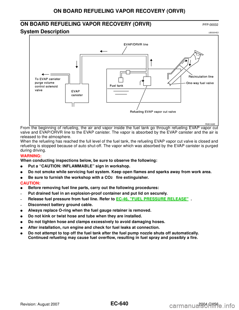
From the beginning of refueling, the air and vapor inside the fuel tank go through refueling EVAP vapor cut
valve and EVAP/ORVR line to the EVAP canister. The vapor is absorbed by the EVAP canister and the air is
released to the atmosphere.
When the refueling has reached the full level of the fuel tank, the refueling EVAP vapor cut valve is closed and
refueling is stopped because of auto shut-off. The vapor which was absorbed by the EVAP canister is purged
during driving.
WAR NIN G:
When conducting inspections below, be sure to observe the following:
�Put a “CAUTION: INFLAMMABLE” sign in workshop.
�Do not smoke while servicing fuel system. Keep open flames and sparks away from work area.
�Be sure to furnish the workshop with a CO2 fire extinguisher.
CAUTION:
�Before removing fuel line parts, carry out the following procedures:
–Put drained fuel in an explosion-proof container and put lid on securely.
–Release fuel pressure from fuel line. Refer to EC-46, "FUEL PRESSURE RELEASE" .
–Disconnect battery ground cable.
�Always replace O-ring when the fuel gauge retainer is removed.
�Do not kink or twist hose and tube when they are installed.
�Do not tighten hose and clamps excessively to avoid damaging hoses.
�After installation, run engine and check for fuel leaks at connection.
�Do not attempt to top off the fuel tank after the fuel pump nozzle shuts off automatically.
Continued refueling may cause fuel overflow, resulting in fuel spray and possibly a fire.
PBIB1068E