Page 1854 of 3371
FRONT BUMPER
EI-13
C
D
E
F
G
H
J
K
L
MA
B
EI
Revision: August 20072004 QX56
FRONT BUMPERPFP:F2022
Removal and InstallationEIS002X7
REMOVAL
1. Remove side screws from fascia assembly.
2. Remove screws from front of fender protector. Refer to EI-23, "
FENDER PROTECTOR" .
1. Lower energy absorber 2. Front bumper side bracket RH 3. Front bumper stay RH
4. Upper bumper reinforcement 5. Plastic clip 6. Upper energy absorber (part of
upper bumper reinforcement)
7. Fastener 8. Front fascia assembly 9. Front fascia bracket
10. Front undercover 11. Fog/turn lamp 12. Fog/turn lamp LH/RH finisher
13. Spring nut 14. Front bumper stay LH 15. Front bumper side bracket LH
16. Plastic clip 16. Headlamp finisher (RH shown)
WIIA0260E
Page 1855 of 3371
EI-14
FRONT BUMPER
Revision: August 20072004 QX56
3. Remove engine undercover.
4. Remove fog/turn lamp finisher and fog/turn lamp.
�Disconnect harnesses.
5. Remove engine underside cover.
6. Remove fasteners, release clips and remove front fascia assembly.
7. Remove plastic clips and remove upper energy absorber.
8. Remove upper bumper reinforcement.
9. Remove plastic clips and remove lower energy absorber.
10. Remove front bumper stays and front bumper side brackets, LH and RH.
INSTALLATION
Installation is in the reverse order of removal.
Page 1857 of 3371

EI-16
REAR BUMPER
Revision: August 20072004 QX56
1. Remove quarter panel trim covers LH and RH.
2. Disconnect sonar sensor harness connector under rear fascia assembly.
3. Release retainer clips on both sides of rear fascia assembly with a 1/4 turn and top S clips and remove
fascia assembly.
4. Remove energy absorber.
5. Remove reinforcement assembly.
6. Remove nuts and remove retainer assembly.
�Remove S clips from retainer assembly.
7. Disconnect sonar sensors from sonar sensor retainers.
8. Remove sonar sensors and harness from rear fascia assembly.
�Disconnect sonar sensors from harness.
�Remove sonar sensor retainers from rear fascia assembly.
9. Remove bolts on each side of tow hitch and remove tow hitch.
10. Remove drafter duct from under LH quarter panel.
Installation is in the reverse order of removal.
1. Retainer assembly 2. Plastic clip 3. S clip
4. Reinforcement assembly 5. Energy absorber 6. Sonar sensor
7. Quarter panel trim cover LH 8. Drafter duct 9. Retainer clip
10. Rear fascia assembly 11. Sonar sensor retainer 12. Tow hitch
13. Sonar sensor harness 14. Quarter panel trim cover RH
Page 1946 of 3371

CYLINDER HEAD
EM-63
C
D
E
F
G
H
I
J
K
L
MA
EM
Revision: August 20072004 QX56
7. Remove valve oil seal using Tool.
8. Replace valve seat if necessary. Refer to EM-68, "
VALVE SEAT REPLACEMENT" .
9. Replace valve guide if necessary. Refer to EM-68, "
VALVE SEAT REPLACEMENT" .
10. Remove spark plug tube, as necessary.
�Remove spark plug tube out of cylinder head using suitable tool.
CAUTION:
�Take care not to damage cylinder head.
�Once removed, spark plug tube will be deformed and cannot be reused. Do not remove it unless
absolutely necessary.
ASSEMBLY
1. Install the valve guide if necessary. Refer to EM-66, "VALVE GUIDE REPLACEMENT" .
2. Install the valve seat if necessary. Refer to EM-68, "
VALVE SEAT REPLACEMENT" .
3. Install valve oil seal using Tool.
�Apply new engine oil on new valve oil seal joint and seal lip.
�Install valve oil seal to specified height "H".
4. Install valves in their original position.
5. Install valve spring seats.
6. Install valve springs.
�Install narrow pitch end (Paint mark side) to cylinder head
side.
7. Install valve spring retainers.Tool number : KV10107902 (J-38959)
WBIA0478E
Tool number : KV10115600 (J-38958)
Height "H" (Without valve spring seat installed)
Intake and exhaust : 14.3 - 14.9 mm (0.563 - 0.587 in)
WBIA0490E
SEM 08 5D
Page 2004 of 3371

DRIVE SHAFT
FAX-7
C
E
F
G
H
I
J
K
L
MA
B
FA X
Revision: August 20072004 QX56
DRIVE SHAFTPFP:39100
Removal and InstallationEDS001B5
REMOVAL
1. Remove wheel and tire using power tool.
2. Remove engine under cover using power tool.
3. Remove wheel sensor harness from mount on knuckle.
CAUTION:
Do not pull on wheel sensor harness.
4. Without disassembling the hydraulic lines, remove brake caliper using power tool. Reposition it aside with
wire. Refer to BR-22, "
Removal and Installation of Brake Caliper and Disc Rotor" .
NOTE:
Avoid depressing brake pedal while brake caliper is removed.
5. Remove coil spring and shock absorber assembly using power tool. Refer to FSU-10, "
Removal and
Installation" .
6. Separate upper link ball joint stud from steering knuckle using
Tool.
�Support lower link with jack.
7. Remove cotter pin, then remove drive shaft nut.
8. Remove drive shaft mounting bolts from front final drive.
9. Remove drive shaft from wheel hub and bearing assembly.
CAUTION:
�When removing drive shaft, do not apply an excessive
angle to drive shaft joint. Also be careful not to exces-
sively extend slide joint.
INSPECTION AFTER REMOVAL
�Move joint up, down, left, right, and in axial direction. Check for any rough movement or significant loose-
ness.
�Check boot for cracks or other damage, and for grease leakage.
�If damaged, disassemble drive shaft to verify damage, and
repair or replace as necessary.
1. Cotter pin 2. Drive shaft nut 3. Drive shaft
LDIA0159E
Tool number : ST29020001 (J-24319-01)
LEIA0095E
RAA0030D
Page 2052 of 3371

FUEL LEVEL SENSOR UNIT, FUEL FILTER AND FUEL PUMP ASSEMBLY
FL-7
C
D
E
F
G
H
I
J
K
L
MA
FL
Revision: August 20072004 QX56
Disconnect the quick connector as follows:
�Hold the sides of the connector, push in tabs and pull out the
tube.
�If the connector and the tube are stuck together, push and pull
several times until they start to move. Then disconnect them
by pulling.
CAUTION:
�The quick connector can be disconnected when the tabs
are completely depressed. Do not twist the quick connec-
tor more than necessary.
�Do not use any tools to disconnect the quick connector.
�Keep the resin tube away from heat. Be especially careful
when welding near the tube.
�Prevent any acid liquids such as battery electrolyte, from
getting on the resin tube.
�Do not bend or twist the resin tube during connection.
�Do not remove the remaining retainer on the hard tube (or
the equivalent) except when the resin tube or the retainer
is replaced.
�When the resin tube or hard tube, or the equivalent, is
replaced, also replace the retainer with a new one (white
colored retainer).
�To keep the quick connector clean and to avoid damage
and contamination from foreign materials, cover the
quick connector with plastic bags or suitable material as
shown.
SF E5 62 A
PBIC1268E
PBIC0163E
Page 2053 of 3371

FL-8Revision: August 2007
FUEL LEVEL SENSOR UNIT, FUEL FILTER AND FUEL PUMP ASSEMBLY
2004 QX56
11. Remove the lock ring using Tool.
12. Remove the fuel level sensor, fuel filter, and fuel pump assem-
bly.
CAUTION:
�Do not bend the float arm during removal.
�Avoid impacts such as dropping when handling the com-
ponents.
INSTALLATION
Installation is in the reverse order of removal.
�Connect the quick connector as follows:
–Check the connection for any damage or foreign materials.
–Align the connector with the pipe, then insert the connector straight into the pipe until a click is heard.
–After connecting the quick connector, make sure that the con-
nection is secure by checking as follows:
–Pull the tube and the connector to make sure they are securely
connected.
–Visually inspect the connector to make sure the two retainer tabs
are securely connected.
INSPECTION AFTER INSTALLATION
1. Turn the ignition switch ON but do not start engine, then check the fuel pipes and hose connections for
leaks while applying fuel pressure to the system.
2. Start the engine and rev it above idle speed, then check that there are no fuel leaks at any of the fuel pipe
and hose connections.Tool number : — (J-46536)
LBIA0389E
PBIC1653E
Page 2056 of 3371
FUEL TANK
FL-11
C
D
E
F
G
H
I
J
K
L
MA
FL
Revision: August 20072004 QX56
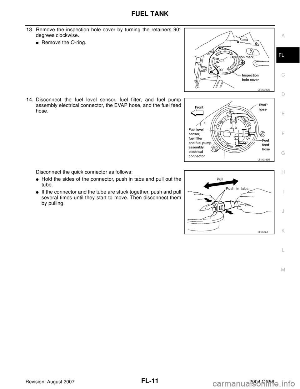
13. Remove the inspection hole cover by turning the retainers 90°
degrees clockwise.
�Remove the O-ring.
14. Disconnect the fuel level sensor, fuel filter, and fuel pump
assembly electrical connector, the EVAP hose, and the fuel feed
hose.
Disconnect the quick connector as follows:
�Hold the sides of the connector, push in tabs and pull out the
tube.
�If the connector and the tube are stuck together, push and pull
several times until they start to move. Then disconnect them
by pulling.
LBIA0382E
LBIA0383E
SF E5 62 A