Page 4200 of 4449
AUTOMATIC DRIVE POSITIONER
SE-71
C
D
E
F
G
H
J
K
L
MA
B
SE
Revision: 2004 November 2004 FX35/FX45
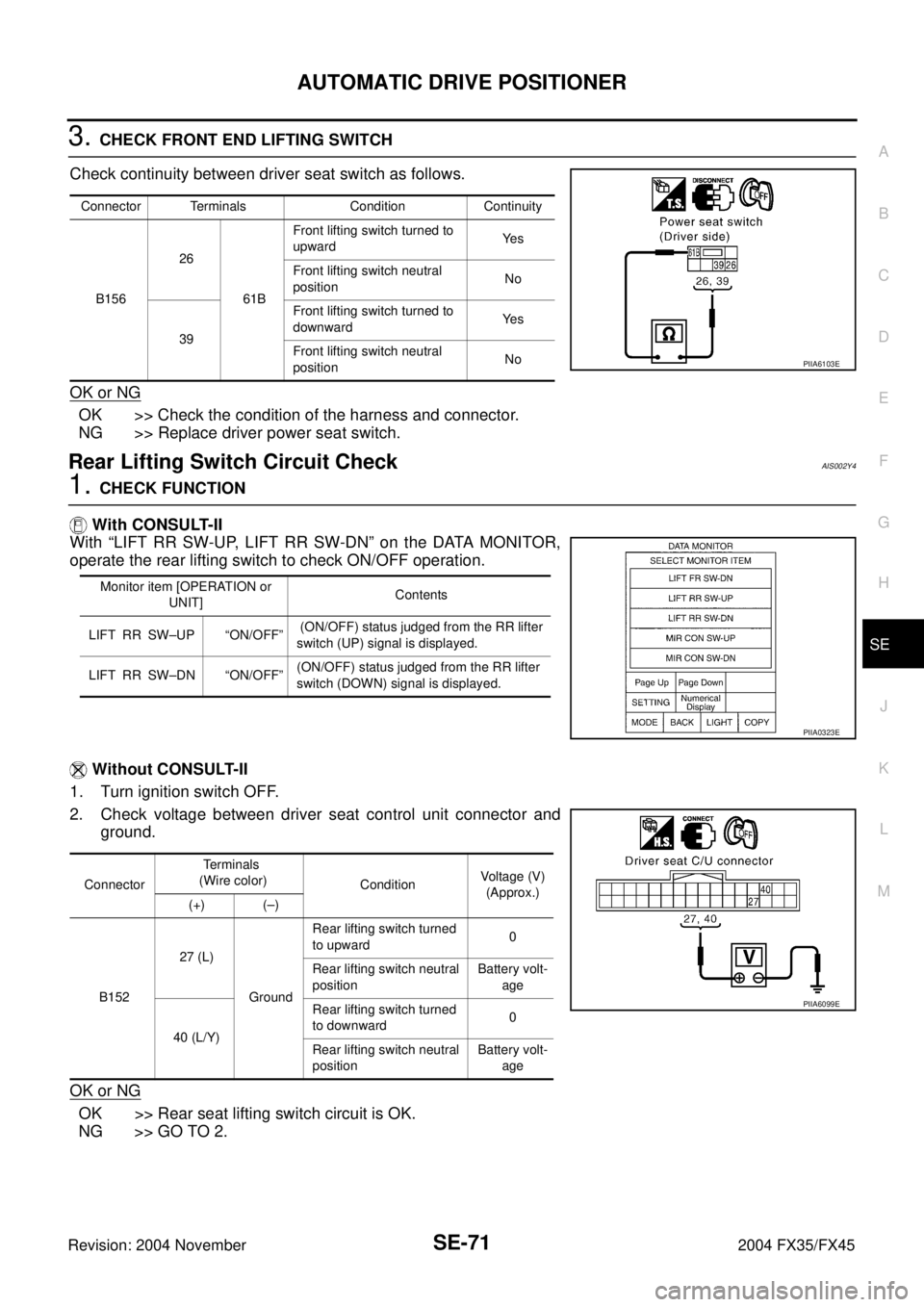
3. CHECK FRONT END LIFTING SWITCH
Check continuity between driver seat switch as follows.
OK or NG
OK >> Check the condition of the harness and connector.
NG >> Replace driver power seat switch.
Rear Lifting Switch Circuit CheckAIS002Y4
1. CHECK FUNCTION
With CONSULT-II
With “LIFT RR SW-UP, LIFT RR SW-DN” on the DATA MONITOR,
operate the rear lifting switch to check ON/OFF operation.
Without CONSULT-II
1. Turn ignition switch OFF.
2. Check voltage between driver seat control unit connector and
ground.
OK or NG
OK >> Rear seat lifting switch circuit is OK.
NG >> GO TO 2.
Connector Terminals Condition Continuity
B15626
61BFront lifting switch turned to
upwardYe s
Front lifting switch neutral
positionNo
39Front lifting switch turned to
downwardYe s
Front lifting switch neutral
positionNo
PIIA6103E
Monitor item [OPERATION or
UNIT]Contents
LIFT RR SW–UP “ON/OFF” (ON/OFF) status judged from the RR lifter
switch (UP) signal is displayed.
LIFT RR SW–DN “ON/OFF”(ON/OFF) status judged from the RR lifter
switch (DOWN) signal is displayed.
PIIA0323E
ConnectorTerminals
(Wire color)
ConditionVoltage (V)
(Approx.)
(+) (–)
B15227 (L)
GroundRear lifting switch turned
to upward0
Rear lifting switch neutral
positionBattery volt-
age
40 (L/Y)Rear lifting switch turned
to downward0
Rear lifting switch neutral
positionBattery volt-
age
PIIA6099E
Page 4211 of 4449
SE-82
AUTOMATIC DRIVE POSITIONER
Revision: 2004 November 2004 FX35/FX45
Detention Switch (P Range Switch) Circuit CheckAIS002XW
1. CHECK FUNCTION
With CONSULT-II
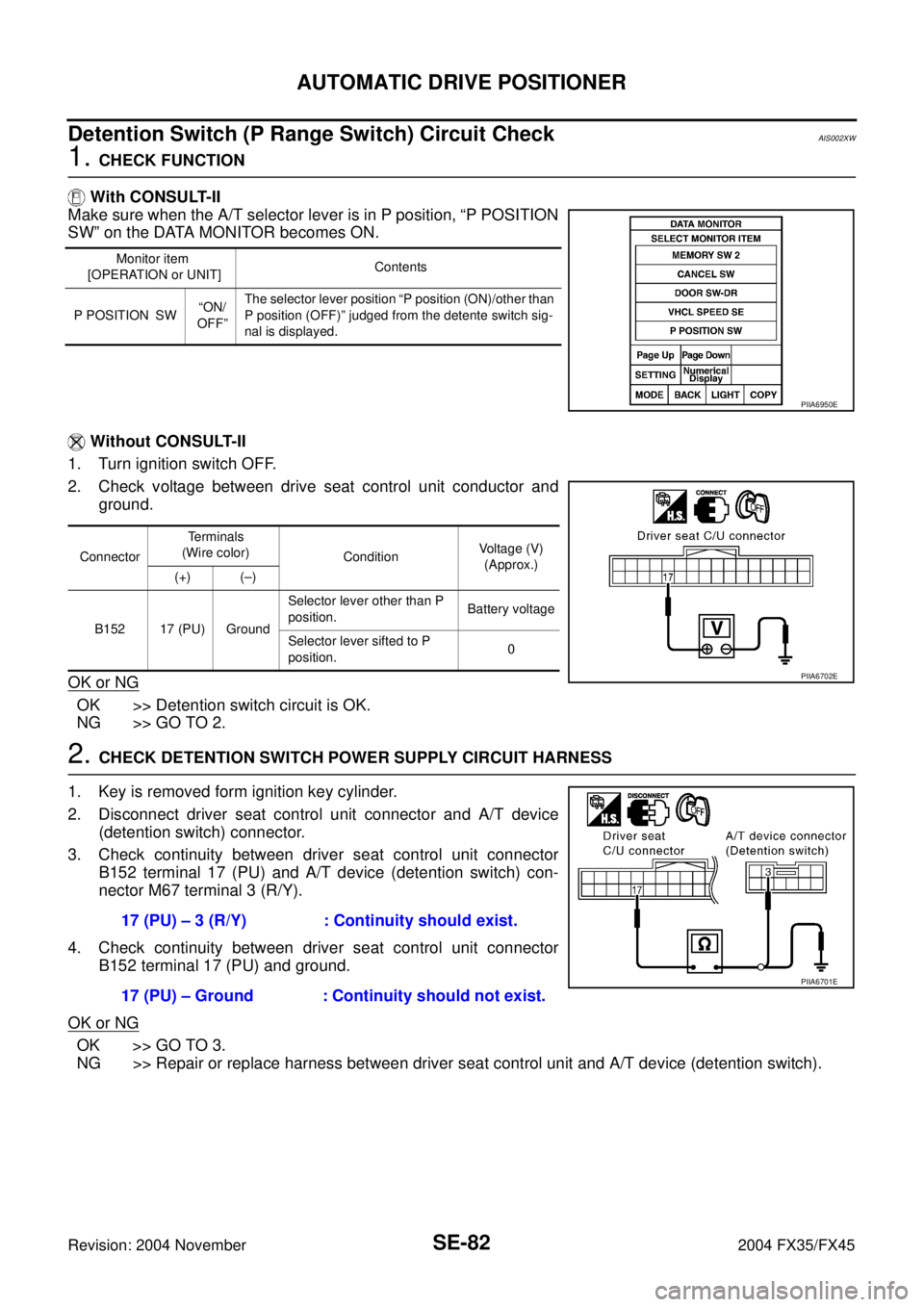
Make sure when the A/T selector lever is in P position, “P POSITION
SW” on the DATA MONITOR becomes ON.
Without CONSULT-II
1. Turn ignition switch OFF.
2. Check voltage between drive seat control unit conductor and
ground.
OK or NG
OK >> Detention switch circuit is OK.
NG >> GO TO 2.
2. CHECK DETENTION SWITCH POWER SUPPLY CIRCUIT HARNESS
1. Key is removed form ignition key cylinder.
2. Disconnect driver seat control unit connector and A/T device
(detention switch) connector.
3. Check continuity between driver seat control unit connector
B152 terminal 17 (PU) and A/T device (detention switch) con-
nector M67 terminal 3 (R/Y).
4. Check continuity between driver seat control unit connector
B152 terminal 17 (PU) and ground.
OK or NG
OK >> GO TO 3.
NG >> Repair or replace harness between driver seat control unit and A/T device (detention switch).
Monitor item
[OPERATION or UNIT]Contents
P POSITION SW“ON/
OFF”The selector lever position “P position (ON)/other than
P position (OFF)” judged from the detente switch sig-
nal is displayed.
PIIA6950E
ConnectorTerminals
(Wire color)
ConditionVoltage (V)
(Approx.)
(+) (–)
B152 17 (PU) GroundSelector lever other than P
position.Battery voltage
Selector lever sifted to P
position.0
PIIA6702E
17 (PU) – 3 (R/Y) : Continuity should exist.
17 (PU) – Ground : Continuity should not exist.
PIIA6701E
Page 4213 of 4449
SE-84
AUTOMATIC DRIVE POSITIONER
Revision: 2004 November 2004 FX35/FX45
2. CHECK KEY SWITCH AND KEY LOCK SOLENOID POWER SUPPLY CIRCUIT
1. Turn ignition switch OFF.
2. Disconnect key switch connector and key lock solenoid connec-
tor.
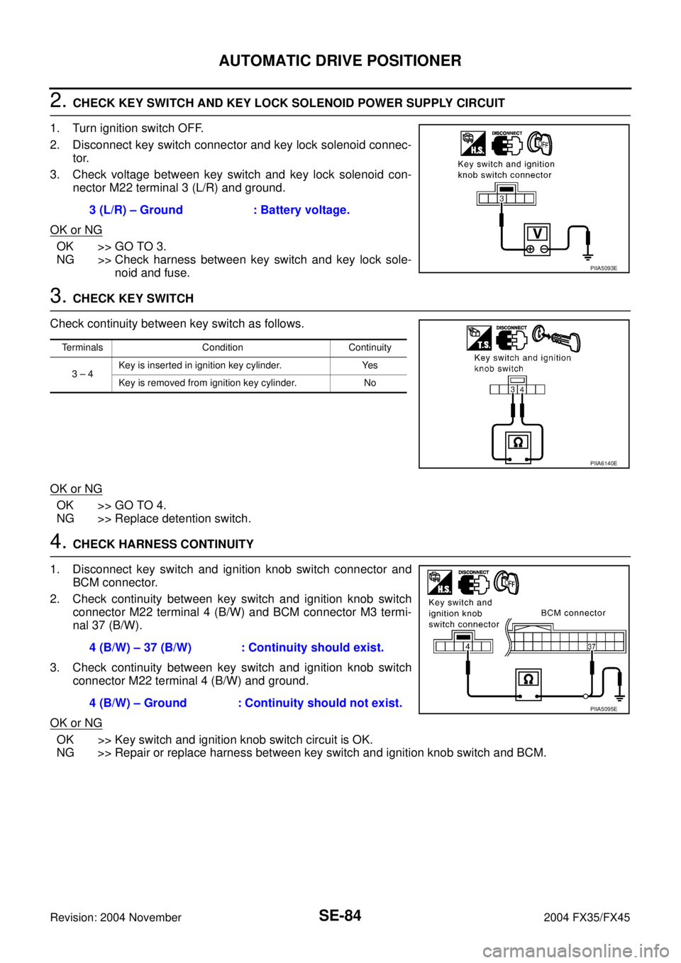
3. Check voltage between key switch and key lock solenoid con-
nector M22 terminal 3 (L/R) and ground.
OK or NG
OK >> GO TO 3.
NG >> Check harness between key switch and key lock sole-
noid and fuse.
3. CHECK KEY SWITCH
Check continuity between key switch as follows.
OK or NG
OK >> GO TO 4.
NG >> Replace detention switch.
4. CHECK HARNESS CONTINUITY
1. Disconnect key switch and ignition knob switch connector and
BCM connector.
2. Check continuity between key switch and ignition knob switch
connector M22 terminal 4 (B/W) and BCM connector M3 termi-
nal 37 (B/W).
3. Check continuity between key switch and ignition knob switch
connector M22 terminal 4 (B/W) and ground.
OK or NG
OK >> Key switch and ignition knob switch circuit is OK.
NG >> Repair or replace harness between key switch and ignition knob switch and BCM.3 (L/R) – Ground : Battery voltage.
PIIA5093E
Terminals Condition Continuity
3 – 4Key is inserted in ignition key cylinder. Yes
Key is removed from ignition key cylinder. No
PIIA6140E
4 (B/W) – 37 (B/W) : Continuity should exist.
4 (B/W) – Ground : Continuity should not exist.
PIIA5095E
Page 4214 of 4449
AUTOMATIC DRIVE POSITIONER
SE-85
C
D
E
F
G
H
J
K
L
MA
B
SE
Revision: 2004 November 2004 FX35/FX45
Key Switch Circuit Check (Without Intelligent Key)AIS003G1
1. CHECK KEY SWITCH
With CONSULT-II
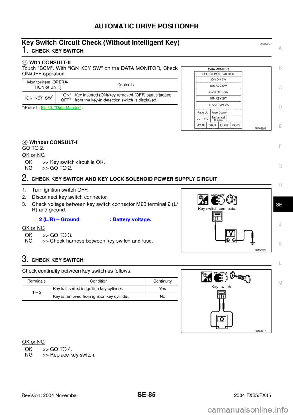
Touch "BCM". With “IGN KEY SW” on the DATA MONITOR, Check
ON/OFF operation.
*:Refer to BL-40, "Data Monitor" .
Without CONSULT-II
GO TO 2.
OK or NG
OK >> Key switch circuit is OK.
NG >> GO TO 2.
2. CHECK KEY SWITCH AND KEY LOCK SOLENOID POWER SUPPLY CIRCUIT
1. Turn ignition switch OFF.
2. Disconnect key switch connector.
3. Check voltage between key switch connector M23 terminal 2 (L/
R) and ground.
OK or NG
OK >> GO TO 3.
NG >> Check harness between key switch and fuse.
3. CHECK KEY SWITCH
Check continuity between key switch as follows.
OK or NG
OK >> GO TO 4.
NG >> Replace key switch.
Monitor item [OPERA-
TION or UNIT]Contents
IGN KEY SW
*“ON/
OFF”Key inserted (ON)/key removed (OFF) status judged
from the key-in detection switch is displayed.
PIIA0298E
2 (L/R) – Ground : Battery voltage.
PIIA5092E
Terminals Condition Continuity
1 – 2Key is inserted in ignition key cylinder. Yes
Key is removed from ignition key cylinder. No
PIIA6141E
Page 4217 of 4449
SE-88
AUTOMATIC DRIVE POSITIONER
Revision: 2004 November 2004 FX35/FX45
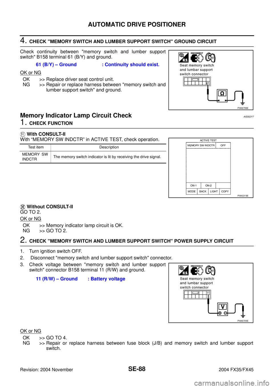
4. CHECK "MEMORY SWITCH AND LUMBER SUPPORT SWITCH" GROUND CIRCUIT
Check continuity between "memory switch and lumber support
switch" B158 terminal 61 (B/Y) and ground.
OK or NG
OK >> Replace driver seat control unit.
NG >> Repair or replace harness between "memory switch and
lumber support switch" and ground.
Memory Indicator Lamp Circuit CheckAIS002Y7
1. CHECK FUNCTION
With CONSULT-II
With “MEMORY SW INDCTR” in ACTIVE TEST, check operation.
Without CONSULT-II
GO TO 2.
OK or NG
OK >> Memory indicator lamp circuit is OK.
NG >> GO TO 2.
2. CHECK "MEMORY SWITCH AND LUMBER SUPPORT SWITCH" POWER SUPPLY CIRCUIT
1. Turn ignition switch OFF.
2. Disconnect "memory switch and lumber support switch" connector.
3. Check voltage between "memory switch and lumber support
switch" connector B158 terminal 11 (R/W) and ground.
OK or NG
OK >> GO TO 4.
NG >> Repair or replace harness between fuse block (J/B) and memory switch and lumber support
switch. 61 (B/Y) – Ground : Continuity should exist.
PIIA6706E
Test item Description
MEMORY SW
INDCTRThe memory switch indicator is lit by receiving the drive signal.
PIIA0319E
11 (R/W) – Ground : Battery voltage
PIIA6705E
Page 4218 of 4449
AUTOMATIC DRIVE POSITIONER
SE-89
C
D
E
F
G
H
J
K
L
MA
B
SE
Revision: 2004 November 2004 FX35/FX45
3. CHECK HARNESS CONTINUITY
1. Disconnect driver seat control unit connector.
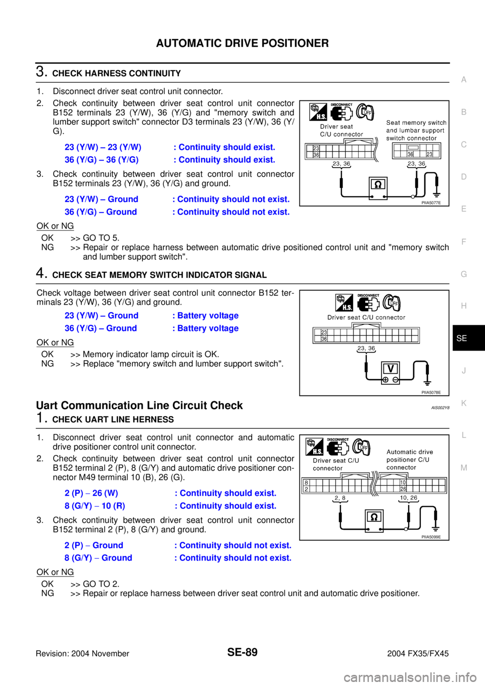
2. Check continuity between driver seat control unit connector
B152 terminals 23 (Y/W), 36 (Y/G) and "memory switch and
lumber support switch" connector D3 terminals 23 (Y/W), 36 (Y/
G).
3. Check continuity between driver seat control unit connector
B152 terminals 23 (Y/W), 36 (Y/G) and ground.
OK or NG
OK >> GO TO 5.
NG >> Repair or replace harness between automatic drive positioned control unit and "memory switch
and lumber support switch".
4. CHECK SEAT MEMORY SWITCH INDICATOR SIGNAL
Check voltage between driver seat control unit connector B152 ter-
minals 23 (Y/W), 36 (Y/G) and ground.
OK or NG
OK >> Memory indicator lamp circuit is OK.
NG >> Replace "memory switch and lumber support switch".
Uart Communication Line Circuit CheckAIS002Y8
1. CHECK UART LINE HERNESS
1. Disconnect driver seat control unit connector and automatic
drive positioner control unit connector.
2. Check continuity between driver seat control unit connector
B152 terminal 2 (P), 8 (G/Y) and automatic drive positioner con-
nector M49 terminal 10 (B), 26 (G).
3. Check continuity between driver seat control unit connector
B152 terminal 2 (P), 8 (G/Y) and ground.
OK or NG
OK >> GO TO 2.
NG >> Repair or replace harness between driver seat control unit and automatic drive positioner.23 (Y/W) – 23 (Y/W) : Continuity should exist.
36 (Y/G) – 36 (Y/G) : Continuity should exist.
23 (Y/W) – Ground : Continuity should not exist.
36 (Y/G) – Ground : Continuity should not exist.
PIIA5077E
23 (Y/W) – Ground : Battery voltage
36 (Y/G) – Ground : Battery voltage
PIIA5078E
2 (P) − 26 (W) : Continuity should exist.
8 (G/Y) − 10 (R) : Continuity should exist.
2 (P) − Ground : Continuity should not exist.
8 (G/Y) − Ground : Continuity should not exist.
PIIA5099E
Page 4220 of 4449
AUTOMATIC DRIVE POSITIONER
SE-91
C
D
E
F
G
H
J
K
L
MA
B
SE
Revision: 2004 November 2004 FX35/FX45
Lumber Support Circuit CheckAIS003C1
1. CHECK LUMBER SUPPORT SWITCH
1. Turn ignition switch OFF.
2. Disconnect l"memory switch and lumber support switch" con-
nector.
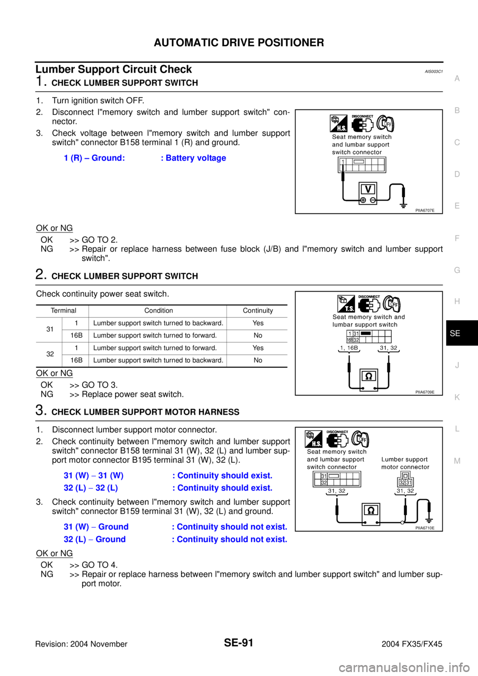
3. Check voltage between l"memory switch and lumber support
switch" connector B158 terminal 1 (R) and ground.
OK or NG
OK >> GO TO 2.
NG >> Repair or replace harness between fuse block (J/B) and l"memory switch and lumber support
switch".
2. CHECK LUMBER SUPPORT SWITCH
Check continuity power seat switch.
OK or NG
OK >> GO TO 3.
NG >> Replace power seat switch.
3. CHECK LUMBER SUPPORT MOTOR HARNESS
1. Disconnect lumber support motor connector.
2. Check continuity between l"memory switch and lumber support
switch" connector B158 terminal 31 (W), 32 (L) and lumber sup-
port motor connector B195 terminal 31 (W), 32 (L).
3. Check continuity between l"memory switch and lumber support
switch" connector B159 terminal 31 (W), 32 (L) and ground.
OK or NG
OK >> GO TO 4.
NG >> Repair or replace harness between l"memory switch and lumber support switch" and lumber sup-
port motor. 1 (R) – Ground: : Battery voltage
PIIA6707E
Terminal Condition Continuity
311 Lumber support switch turned to backward. Yes
16B Lumber support switch turned to forward. No
321 Lumber support switch turned to forward. Yes
16B Lumber support switch turned to backward. No
PIIA6709E
31 (W) − 31 (W) : Continuity should exist.
32 (L) − 32 (L) : Continuity should exist.
31 (W) − Ground : Continuity should not exist.
32 (L) − Ground : Continuity should not exist.
PIIA6710E
Page 4232 of 4449
FRONT SEAT
SE-103
C
D
E
F
G
H
J
K
L
MA
B
SE
Revision: 2004 November 2004 FX35/FX45
REMOVAL
When removing or installing the seat trim, carefully handle it to keep dirt out and avoid damage.
CAUTION:
�Before removing the front seat, turn ignition switch OFF, disconnect both battery cables and wait
at least 3 minutes.
�When checking the power seat circuit for continuity using a circuit tester, do not confuse its con-
nector with the side air bag module connector. Such an error may cause the air bag to deploy.
�Do not drop, tilt, or bump the side air bag module installing in the seat. Always handle it with care.
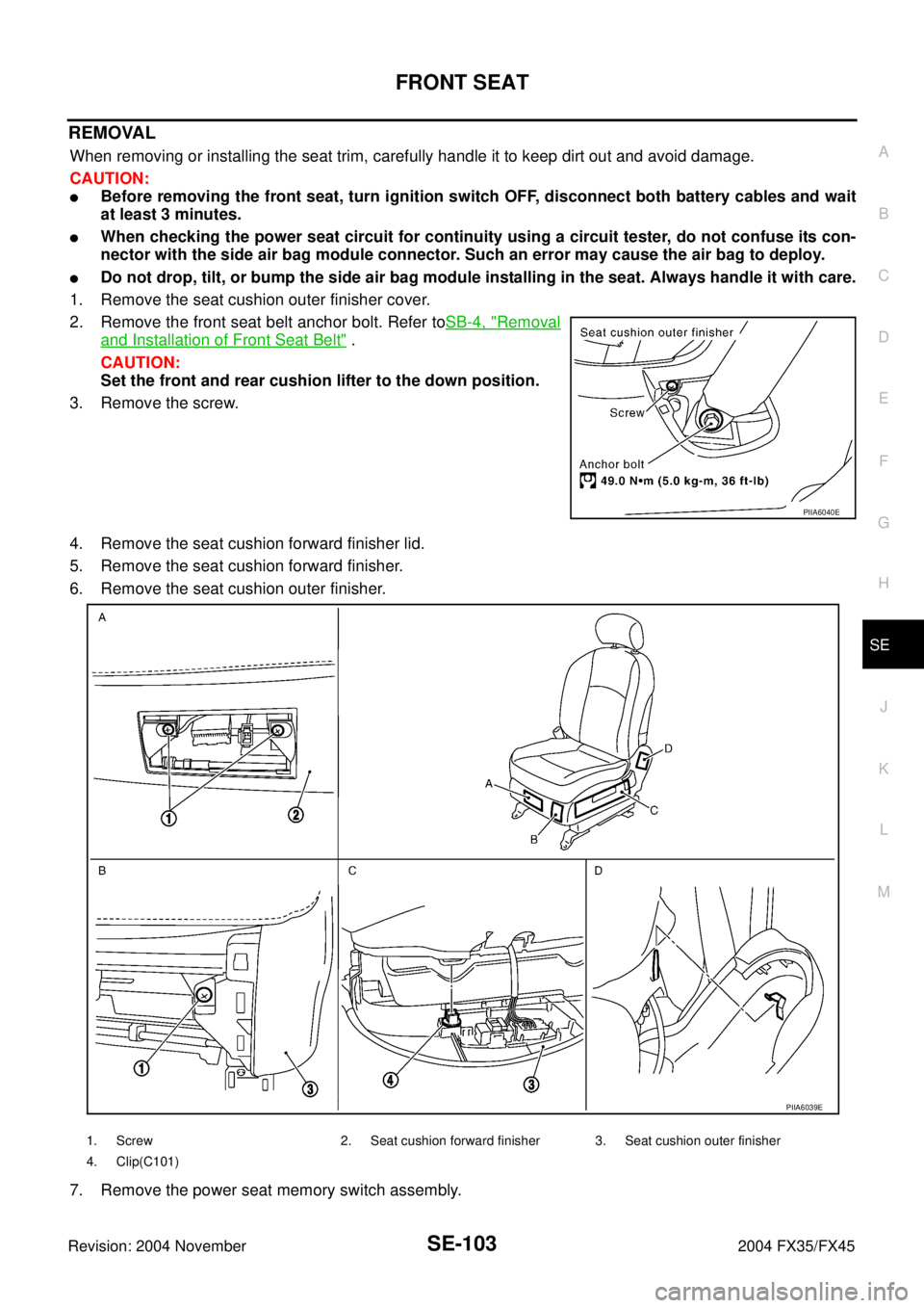
1. Remove the seat cushion outer finisher cover.
2. Remove the front seat belt anchor bolt. Refer toSB-4, "
Removal
and Installation of Front Seat Belt" .
CAUTION:
Set the front and rear cushion lifter to the down position.
3. Remove the screw.
4. Remove the seat cushion forward finisher lid.
5. Remove the seat cushion forward finisher.
6. Remove the seat cushion outer finisher.
7. Remove the power seat memory switch assembly.
PIIA6040E
PIIA6039E
1. Screw 2. Seat cushion forward finisher 3. Seat cushion outer finisher
4. Clip(C101)