Page 4093 of 4449

SC-4
BATTERY
Revision: 2004 November 2004 FX35/FX45
BATTERYPFP:AYBGL
How to Handle BatteryAKS00799
CAUTION:
�If it becomes necessary to start the engine with a booster battery and jumper cables, use a 12-volt
booster battery.
�After connecting battery cables, ensure that they are tightly clamped to battery terminals for good
contact.
METHODS OF PREVENTING OVER-DISCHARGE
The following precautions must be taken to prevent over-discharging
a battery.
�The battery surface (particularly its top) should always be kept
clean and dry.
�The terminal connections should be clean and tight.
�At every routine maintenance, check the electrolyte level.
This also applies to batteries designated as “low maintenance”
and “maintenance-free”.
�When the vehicle is not going to be used over a long period of
time, disconnect the negative battery cable.
�Check the charge condition of the battery.
Periodically check the specific gravity of the electrolyte. Keep a
close check on charge condition to prevent over-discharge.
MEL040F
MEL041F
MEL042F
Page 4104 of 4449

STARTING SYSTEM
SC-15
C
D
E
F
G
H
I
J
L
MA
B
SC
Revision: 2004 November 2004 FX35/FX45
DIAGNOSTIC PROCEDURE 1
Check “B” Terminal Circuit
1. CHECK POWER SUPPLY FOR STARTER MOTOR “B” TERMINAL
1. Remove fuel pump fuse.
2. Crank or start the engine (where possible) until the fuel pressure is released.
3. Turn ignition switch OFF.
4. Make sure that the starter motor B terminal E313 terminal 2 (B)
*1 or (B/R)*2 connection is clean and tight.
5. Check voltage between starter motor B terminal E313 terminal 2
(B)
*1 or (B/R)*2 and ground using a digital circuit tester.
NOTE:
*1: VK45DE, *2: VQ35DE
OK or NG
OK >> GO TO 2.
NG >> Check harness between the battery and the starter
motor for open circuit.
2. CHECK BATTERY HARNESS CONNECTION (VOLTAGE DROP TEST)
Check voltage between starter motor B terminal E313 terminal 2
(B)
*1 or (B/R)*2 and battery positive terminal using a digital circuit
tester.
NOTE:
*1: VK45DE, *2: VQ35DE
OK or NG
OK >> GO TO 3.
NG >> Check harness between the battery and the starter
motor for poor continuity.
3. CHECK STARTER MOTOR GROUND CIRCUIT (VOLTAGE DROP TEST)
1. Turn ignition switch OFF.
2. Check voltage between starter motor case and battery negative
terminal using a digital circuit tester.
OK or NG
OK >> Starter motor “B” terminal circuit is OK. Further inspec-
tion necessary. Refer to SC-14, "
WORK FLOW" .
NG >> Check the starter motor case and ground for poor conti-
nuity. Battery voltage should exist.
PKIA2842E
When the ignition switch is in START position,
Voltage: Less than 0.5V
PKIA2370E
When the ignition switch is in START position,
Voltage: Less than 0.2V
PKIA2943E
Page 4105 of 4449

SC-16
STARTING SYSTEM
Revision: 2004 November 2004 FX35/FX45
DIAGNOSTIC PROCEDURE 2
Check “S” Connector Circuit
1. CHECK POWER SUPPLY FOR STARTER MOTOR “S” CONNECTOR
1. Remove fuel pump fuse.
2. Crank or start the engine (where possible) until the fuel pressure is released.
3. Turn ignition switch OFF.
4. Disconnect starter motor S connector.
5. Check voltage between starter motor harness connector E312
*1
or F33*2 terminal 1 (B) and ground using a digital circuit tester.
NOTE:
*1: VK45DE, *2: VQ35DE
OK or NG
OK >> GO TO 2.
NG >> Check the following.
�40A fusible link (letter F , located in fuse and fusible
link box)
�Ignition switch
�Starter relay [within the IPDM E/R (intelligent power distribution module engine room)].
�Harness for open or short
2. CHECK “S” TERMINAL CONNECTION (VOLTAGE DROP TEST)
1. Turn ignition switch OFF.
2. Connect starter motor S connector.
3. Check voltage between starter motor harness connector E312
*1
or F33*2 terminal 1 (B) and battery positive terminal using a dig-
ital circuit tester.
NOTE:
*1: VK45DE, *2: VQ35DE
OK or NG
OK >> Starter motor “S” connector circuit is OK. Further inspec-
tion necessary. Refer to SC-14, "
WORK FLOW" .
NG >> Check harness between the battery and the starter motor “S” connector for poor continuity.
MINIMUM SPECIFICATION OF CRANKING VOLTAGE REFERENCING COOLANT TEMPERA-
TURE
When the ignition switch is in START position,
Battery voltage should exist.
PKIA2807E
When the ignition switch is in START position,
Voltage: Less than 1V
PKIA2808E
Engine coolant temperature Voltage V
−30°C to −20°C (−22°F to −4°F) 8.4
−19°C to −10°C (−2°F to 14°F) 8.9
−9°C to 0°C (16°F to 32°F) 9.3
More than 1°C (More than 34°F) 9.7
Page 4115 of 4449

SC-26
CHARGING SYSTEM
Revision: 2004 November 2004 FX35/FX45
Trouble Diagnosis with Battery/Starting/Charging System TesterAKS0079K
NOTE:
To ensure a complete and thorough diagnosis, the battery, starter and alternator test segments must be done
as a set from start to finish.
1. Turn off all loads on the vehicle electrical system.
2. Perform battery and starting system test with Battery/Starting/
Charging system tester.
3. Press “ENTER” to begin the charging system test.
4. Start engine.
5. Press “ENTER” until “LOADS OFF REV ENGINE 5 SEC” is dis-
played.
6. Raise and hold the engine speed at 1,500 to 2,000 rpm for about
5 seconds, then return the engine to idle.
Once the increase in engine rpm is detected, press “ENTER” to
continue.
NOTE:
�If after 30 seconds an increase in engine idle speed is not
detected, “RPM NOT DETECTED” will display.
�Some engines may have a higher idle initially after starting,
particularly when the engine is cold. The tester may detect
this without any other action being taken. If this occurs, con-
tinue on with the testing process. The final results will not be affected.
7. The tester now checks the engine at idle and performs the
DIODE/RIPPLE check.
8. When complete, the tester will prompt you to turn on the follow-
ing electrical loads.
�Heater fan set to highest speed. Do not run the A/C or wind-
shield defroster.
�Headlamp high beam
�Rear window defogger
NOTE:
Do not run the windshield wipers or any other cyclical loads.
9. Press “ENTER” to continue.
SEL417X
SEL418X
SEL419X
SEL420X
Page 4119 of 4449

SC-30
CHARGING SYSTEM
Revision: 2004 November 2004 FX35/FX45
DIAGNOSTIC PROCEDURE 2
Check “B” Terminal Circuit
1. CHECK “B” TERMINAL CONNECTION
1. Turn ignition switch OFF.
2. Check to see if “B” terminal is clean and tight.
OK or NG
OK >> GO TO 2. Confirm repair by performing complete Battery/Starting/Charging system test.
NG >> Repair “B” terminal connection.
2. CHECK ALTERNATOR “B” TERMINAL CIRCUIT
Check voltage between alternator B terminal E307 terminal 1 (B/R)
and ground using a digital circuit tester.
OK or NG
OK >> GO TO 3.
NG >> Check the following.
�120A fusible link [fusible link holder (VK45DE and
VQ35DE AWD)]
�Harness for open or short between alternator and fus-
ible link (VK45DE and VQ35DE AWD)
�Harness for open or short between alternator and battery (VQ35DE 2WD)
3. CHECK “B” TERMINAL CONNECTION (VOLTAGE DROP TEST)
1. Start the engine.
2. When the engine running at idle and warm, check voltage
between alternator B terminal E307 terminal 1 (B/R) and battery
positive terminal using a digital circuit tester.
OK or NG
OK >> Replace the alternator. Confirm repair by performing
complete Battery/Starting/Charging system test.
NG >> Check harness between the battery and the alternator
for poor continuity. Battery voltage should exist.
PKIA2944E
Voltage: Less than 0.2V
PKIA2366E
Page 4121 of 4449

SC-32
CHARGING SYSTEM
Revision: 2004 November 2004 FX35/FX45
DIAGNOSTIC PROCEDURE 4
Check “B” Terminal Circuit
1. CHECK “B” TERMINAL CONNECTION
1. Turn ignition switch OFF.
2. Check to see if “B” terminal is clean and tight.
OK or NG
OK >> GO TO 2. Confirm repair by performing complete Battery/Starting/Charging system test.
NG >> Repair “B” terminal connection.
2. CHECK ALTERNATOR “B” TERMINAL CIRCUIT
Check voltage between alternator B terminal E307 terminal 1 (B/R)
and ground using a digital circuit tester.
OK or NG
OK >> GO TO 3.
NG >> Check the following.
�120A fusible link [fusible link holder (VK45DE and
VQ35DE AWD)]
�Harness for open or short between alternator and fus-
ible link (VK45DE and VQ35DE AWD)
�Harness for open or short between alternator and battery (VQ35DE 2WD)
3. CHECK “B” TERMINAL CONNECTION (VOLTAGE DROP TEST)
1. Start the engine.
2. When the engine running at idle and warm, check voltage
between alternator B terminal E307 terminal 1 (B/R) and battery
positive terminal using a digital circuit tester.
OK or NG
OK >> GO TO 4.
NG >> Check harness between the battery and the alternator
for poor continuity.
4. CHECK ALTERNATOR DRIVE BELT TENSION
1. Turn ignition switch OFF.
2. Check alternator drive belt tension. Refer to EM-169, "
Checking Drive Belts" (VK45DE) or EM-15,
"Checking Drive Belts" (VQ35DE) in “ENGINE MECHANICAL (EM)” section.
YES or NO
YES >> Replace the alternator. Confirm repair by performing complete Battery/Starting/Charging system
test.
NO >> Readjust drive belt tension. Refer to EM-169, "
Tension Adjustment" (VK45DE) or EM-15, "Te n -
sion Adjustment" (VQ35DE) in “ENGINE MECHANICAL (EM)” section. Battery voltage should exist.
PKIA2944E
Voltage: Less than 0.2V
PKIA2366E
Does drive belt tension normal?
Page 4122 of 4449

CHARGING SYSTEM
SC-33
C
D
E
F
G
H
I
J
L
MA
B
SC
Revision: 2004 November 2004 FX35/FX45
DIAGNOSTIC PROCEDURE 5
Check “S” Terminal Circuit
1. CHECK “S” TERMINAL CONNECTION
1. Turn ignition switch OFF.
2. Check to see if “S” terminal is clean and tight.
OK or NG
OK >> GO TO 2.
NG >> Repair “S” terminal connection. Confirm repair by performing complete Battery/Starting/Charging
system test.
2. CHECK ALTERNATOR “S” TERMINAL CIRCUIT
Check voltage between alternator harness connector E311
*1 or
F26
*2 terminal 4 (LG) and ground using a digital circuit tester.
NOTE:
*1: VK45DE, *2: VQ35DE
OK or NG
OK >> GO TO 3.
NG >> Check the following.
�10A fuse (No. 33, located in fuse and fusible link box)
�Harness for open or short between alternator and
fuse
3. CHECK “S” TERMINAL CONNECTION (VOLTAGE DROP TEST)
1. Start the engine.
2. When the engine running at idle and warm, check voltage
between alternator connector E311
*1 or F26*2 terminal 4 (LG)
and battery positive terminal using a digital circuit tester.
NOTE:
*1: VK45DE, *2: VQ35DE
OK or NG
OK >> Replace the alternator. Confirm repair by performing
complete Battery/Starting/Charging system test.
NG >> Check harness between the battery and the alternator for poor continuity.
MALFUNCTION INDICATOR
The IC regulator warning function activates to illuminate “CHARGE” warning lamp, if any of the following
symptoms occur while alternator is operating:
�Excessive voltage is produced.
�No voltage is produced.Battery voltage should exist.
PKIA2816E
Voltage: Less than 0.2V
PKIA2817E
Page 4124 of 4449
CHARGING SYSTEM
SC-35
C
D
E
F
G
H
I
J
L
MA
B
SC
Revision: 2004 November 2004 FX35/FX45
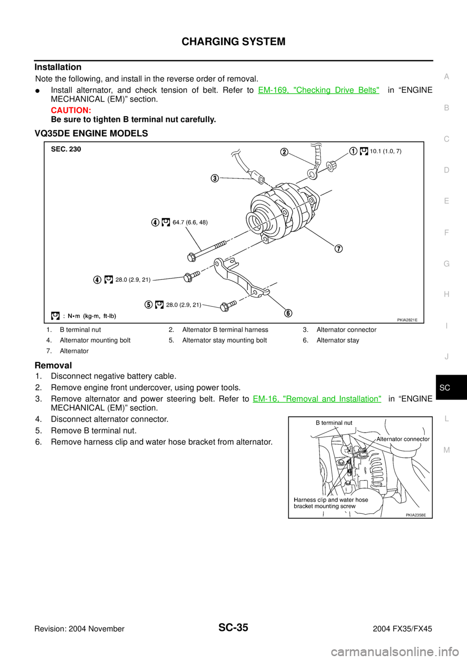
Installation
Note the following, and install in the reverse order of removal.
�Install alternator, and check tension of belt. Refer to EM-169, "Checking Drive Belts" in “ENGINE
MECHANICAL (EM)” section.
CAUTION:
Be sure to tighten B terminal nut carefully.
VQ35DE ENGINE MODELS
Removal
1. Disconnect negative battery cable.
2. Remove engine front undercover, using power tools.
3. Remove alternator and power steering belt. Refer to EM-16, "
Removal and Installation" in “ENGINE
MECHANICAL (EM)” section.
4. Disconnect alternator connector.
5. Remove B terminal nut.
6. Remove harness clip and water hose bracket from alternator.
1. B terminal nut 2. Alternator B terminal harness 3. Alternator connector
4. Alternator mounting bolt 5. Alternator stay mounting bolt 6. Alternator stay
7. Alternator
PKIA2821E
PKIA2358E