Page 3812 of 4449

MA-25
C
D
E
F
G
H
I
J
K
MA
B
MA
Revision: 2004 November 2004 FX35/FX45
9. Stop engine and wait for 15 minutes.
10. Check the engine oil level.
Changing Oil FilterALS")
ENGINE MAINTENANCE (VK45DE ENGINE)
MA-25
C
D
E
F
G
H
I
J
K
MA
B
MA
Revision: 2004 November 2004 FX35/FX45
9. Stop engine and wait for 15 minutes.
10. Check the engine oil level.
Changing Oil FilterALS000GV
REMOVAL
1. Remove front engine undercover with power tool.
2. Using the oil filter wrench (SST), remove the oil filter.
CAUTION:
�Oil filter is provided with relief valve.
Use Genuine Nissan Oil Filter or equivalent.
�Be careful not to get burned when engine and engine oil
may be hot.
�When removing, prepare a shop cloth to absorb any
engine oil leakage or spillage.
�Do not allow engine oil to adhere to drive belts.
�Completely wipe off any engine oil that adhere to engine
and vehicle.
INSTALLATION
1. Remove foreign materials adhering to oil filter installation surface.
2. Apply engine oil to the oil seal circumference of the new oil filter.
3. Screw oil filter manually until it touches the installation surface,
then tighten it by 2/3 turn. Or tighten to specification.
INSPECTION AFTER INSTALLATION
1. After warming up engine, check for engine oil leakage.
2. Stop engine and wait for 15 minutes.
3. Check the engine oil level and add engine oil. Refer to MA-24, "
Changing Engine Oil" .
PBIC0801E
PBIC1525E
SMA010
Oil filter:
:17.7 N·m (1.8 kg-m, 13 ft-lb)
SMA229B
Page 3814 of 4449
ENGINE MAINTENANCE (VK45DE ENGINE)
MA-27
C
D
E
F
G
H
I
J
K
MA
B
MA
Revision: 2004 November 2004 FX35/FX45
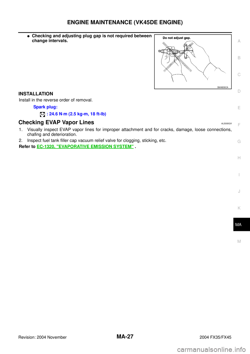
�Checking and adjusting plug gap is not required between
change intervals.
INSTALLATION
Install in the reverse order of removal.
Checking EVAP Vapor LinesALS000GX
1. Visually inspect EVAP vapor lines for improper attachment and for cracks, damage, loose connections,
chafing and deterioration.
2. Inspect fuel tank filler cap vacuum relief valve for clogging, sticking, etc.
Refer to EC-1320, "
EVAPORATIVE EMISSION SYSTEM" .
SMA806CA
Spark plug:
: 24.6 N·m (2.5 kg-m, 18 ft-lb)
Page 3815 of 4449

MA-28
CHASSIS AND BODY MAINTENANCE
Revision: 2004 November 2004 FX35/FX45
CHASSIS AND BODY MAINTENANCEPFP:00100
Checking Exhaust SystemALS000FG
Check exhaust pipes, muffler and mounting for improper attachment,
leaks, cracks, damage, chafing or deterioration.
Checking A/T FluidALS000GB
1. Warm up engine.
2. Check for fluid leakage.
3. Remove the tightening bolt for ATF level gauge.
4. Before driving, fluid level can be checked at fluid temperatures of 30 to 50°C (86 to 122°F) using “COLD”
range on ATF level gauge as follows.
a. Park vehicle on level surface and set parking brake.
b. Start engine and move selector lever through each gear position. Leave selector lever in “P” position.
c. Check fluid level with engine idling.
d. Remove ATF level gauge and wipe clean with lint-free paper.
CAUTION:
When wiping away the fluid level gauge, always use lint-free paper, not a cloth one.
e. Re-insert ATF level gauge into charging pipe as far as it will go.
CAUTION:
To check fluid level, insert the ATF level gauge until the cap contacts the end of the charging pipe,
with the gauge reversed from the normal attachment conditions.
f. Remove ATF level gauge and note reading. If reading is at low side of range, add fluid to the charging
pipe.
CAUTION:
Do not overfill.
5. Drive vehicle for approximately 5 minutes in urban areas.
6. Make the fluid temperature approximately 65°C (149°F).
SMA211A
Page 3817 of 4449

MA-30
CHASSIS AND BODY MAINTENANCE
Revision: 2004 November 2004 FX35/FX45
Changing A/T FluidALS000GC
1. Warm up ATF.
2. Stop engine.
3. Remove the tightening bolt for ATF level gauge.
4. Drain ATF from drain plug and refill with new ATF. Always refill same volume with drained fluid.
�To replace the ATF, pour in new fluid at the charging pipe with the engine idling and at the same time
drain the old fluid from the radiator cooler hose return side.
�When the color of the fluid coming out is about the same as the color of the new fluid, the replacement
is complete. The amount of new transmission fluid to use should be 30 to 50% increase of the stipu-
lated amount.
CAUTION:
�Use only Genuine NISSAN Matic J ATF. Do not mix with other fluid.
�Using automatic transmission fluid other than Genuine NISSAN Matic J ATF will cause deterio-
ration in driveability and automatic transmission durability, and may damage the automatic
transmission, which is not covered by the warranty.
�When filling ATF, take care not to splash heat generating parts such as exhaust with ATF.
�Do not reuse drain plug gasket.
5. Run engine at idle speed for 5 minutes.
6. Check fluid level and condition. Refer to MA-28, "
Checking A/T Fluid" . If fluid is still dirty, repeat step 2.
through 5.
7. Install the removed ATF level gauge in the fluid charging pipe.
Checking Transfer FluidALS000GD
Check for oil leakage and oil level.
CAUTION:
Never start engine while checking oil level.ATF: Genuine NISSAN Matic J ATF
Fluid capacity: 10.3 (10-7/8 US qt, 9-1/8 lmp qt)
Drain plug:
: 34 N·m (3.5 kg-m, 25 ft-lb)
Level gauge bolt:
: 5.1 N·m (0.52 kg-m, 45 in-lb)
Filler plug:
: 34.5 N·m (3.5 kg-m, 25 ft-lb)
SDIA2028E
Page 3823 of 4449

MA-36
CHASSIS AND BODY MAINTENANCE
Revision: 2004 November 2004 FX35/FX45
Checking Power Steering Fluid and LinesALS000FV
Check fluid level in reservoir tank with engine off.
Use “HOT” range at fluid temperatures of 50 to 80°C (122 to 176°F)
or “COLD” range at fluid temperatures of 0 to 30°C (32 to 86°F).
CAUTION:
�Do not overfill.
�Recommended fluid is Genuine NISSAN PSF or equivalent.
Refer to MA-12, "
RECOMMENDED FLUIDS AND LUBRI-
CANTS"
�Check lines for improper attachment, leaks, cracks, dam-
age, loose connections, chafing and deterioration.
�Check rack boots for accumulation of power steering fluid.
Axle and Suspension PartsALS000FW
Check front and rear axle and suspension parts for excessive play,
cracks, wear or other damage.
�Shake each wheel to check for excessive play.
�Check wheel bearings for smooth operation.
�Check axle and suspension nuts and bolts for looseness.
�Check strut (shock absorber) for oil leakage or other damage.
�Check suspension ball joint for grease leakage and ball joint
dust cover for cracks or other damage.
SST850C
SST851C
SMA525A
SFA392B
Page 3826 of 4449

MA-39
C
D
E
F
G
H
I
J
K
MA
B
MA
Revision: 2004 November 2004 FX35/FX45
SERVICE DATA AND SPECIFICATIONS (SDS)PFP:00030
Standard and LimitALS000G0
BELT DEFLECTION A")
SERVICE DATA AND SPECIFICATIONS (SDS)
MA-39
C
D
E
F
G
H
I
J
K
MA
B
MA
Revision: 2004 November 2004 FX35/FX45
SERVICE DATA AND SPECIFICATIONS (SDS)PFP:00030
Standard and LimitALS000G0
BELT DEFLECTION AND TENSION (VQ35DE)
*: If belt tension gauge cannot be installed at check points shown, check drive belt tension at different location on the belt.
BELT DEFLECTION AND TENSION (VK45DE)
ENGINE COOLANT CAPACITY (APPROXIMATE) (VQ35DE)
Unit: (US qt, lmp qt)
ENGINE COOLANT CAPACITY (APPROXIMATE) (VK45DE)
Unit: (US qt, lmp qt)
RADIATOR
Unit: kPa (kg/cm2 , psi)
ENGINE OIL CAPACITY (APPROXIMATE) (VQ35DE)
Unit: (US qt, lmp qt) ItemsDeflection adjustment Unit: mm (in) Tension adjustment* Unit: N (kg, lb)
Used belt
New beltUsed belt
New belt
Limit After adjustment Limit After adjustment
Alternator and
power steering
oil pump belt 7 (0.28)4 - 5
(0.16 - 0.20)3.5 - 4.5
(0.138 - 0.177)294 (30, 66)730 - 818
(74.5 - 83.5,
164 - 184)838 - 926
(85.5 - 94.5,
188 - 208)
Air conditioner
compressor belt 12 (0.47)9 -10
(0.35 - 0.39)8 - 9
(0.31 - 0.35)196 (20, 44)348 - 436
(35.5 - 44.5,
78 - 98)470 - 559
(48 - 57,
106 - 126)
Applied pushing
force98 N (10 kg, 22 lb) —
KBIA1731J
Tension of drive belts Auto-adjustment by auto tensioner
Engine coolant capacity (With reservoir tank at “MAX” level) 8.6 (9-1/8, 7-5/8)
Reservoir tank engine coolant capacity (At “MAX” level) 0.8 (7/8, 3/4)
Engine coolant capacity (With reservoir tank at “MAX” level) 10.0 (10-5/8, 8-3/4)
Reservoir tank engine coolant capacity (At “MAX” level) 0.8 (7/8, 3/4)
Cap relief pressureStandard 78 - 98 (0.8 - 1.0, 11 - 14)
Limit 59 (0.6, 9)
Leakage test pressure157 (1.6, 23)
Drain and refill With oil filter change 4.7 (5, 4-1/8)
Without oil filter change 4.4 (4-5/8, 3-7/8)
Dry engine (Overhaul) 5.4 (5-3/4, 4-3/4)
Page 3855 of 4449

Revision: 2004 November 2004 FX35/FX45
CONSULT-IIAKS005SC
CONSULT-II performs the following functions with combination of data receiv")
PG-20
IPDM E/R (INTELLIGENT POWER DISTRIBUTION MODULE ENGINE ROOM)
Revision: 2004 November 2004 FX35/FX45
CONSULT-IIAKS005SC
CONSULT-II performs the following functions with combination of data receiving, command and transmission
using the CAN communication line from the IPDM E/R.
CONSULT-II INSPECTION PROCEDURE
CAUTION:
If CONSULT-II is used with no connection of CONSULT-II CONVERTER, malfunctions might be
detected in self-diagnosis depending on control unit which carry out CAN communication.
1. With the ignition switch OFF, connect CONSULT-II and CON-
SULT-II CONVERTER to the data link connector, then turn the
ignition switch ON.
2. Touch “START (NISSAN BASED VHCL)”.
3. Touch “IPDM E/R” on “SELECT SYSTEM” screen.
�If “IPDM E/R” is not displayed, print “SELECT SYSTEM”
screen, then refer to GI-40, "
CONSULT-II Data Link Connec-
tor (DLC) Circuit" .
Inspection Item, Diagnosis Mode Description
SELF-DIAG RESULTS The IPDM E/R performs diagnosis of the CAN communication and self-diagnosis.
DATA MONITOR The input/output data of the IPDM E/R is displayed in real time.
CAN DIAG SUPPORT MNTR The result of transmit/receive diagnosis of CAN communication can be read.
ACTIVE TEST The IPDM E/R sends a drive signal to electronic components to check their operation.
PBIB1503E
SKIA3098E
SKIA5036E
Page 3856 of 4449

PG-21
C
D
E
F
G
H
I
J
L
MA
B
PG
Revision: 2004 November 2004 FX35/FX45
4. Select the desired part to be diagnosed on the “SELECT DIAG
MOD")
IPDM E/R (INTELLIGENT POWER DISTRIBUTION MODULE ENGINE ROOM)
PG-21
C
D
E
F
G
H
I
J
L
MA
B
PG
Revision: 2004 November 2004 FX35/FX45
4. Select the desired part to be diagnosed on the “SELECT DIAG
MODE” screen.
SELF-DIAG RESULTS
Operation Procedure
1. Touch “SELF-DIAG RESULTS” on “SELECT DIAG MODE” screen.
2. Check display content in self-diagnostic results.
Display Item List
NOTE:
The details for display of the period are as follows:
�CRNT: Error currently detected with IPDM E/R.
�PAST: Error detected in the past and memorized with IPDM E/R.
PKIA6016E
Display ItemsCONSULT-II
display codeMalfunction detecting conditionTIME
Possible causes
CRNT PAST
NO DTC IS
DETECTED.FURTHER
TESTING MAY BE
REQUIRED.-----
CAN COMM CIRC U1000
�If CAN communication reception/transmis-
sion data has a malfunction, or if any of the
control units malfunction, data reception/
transmission cannot be confirmed.
�When the data in CAN communication is not
received before the specified time××Any of or several items
below have errors.
�TRANSMIT DIAG
�ECM
�BCM/SEC