Page 3858 of 4449

IPDM E/R (INTELLIGENT POWER DISTRIBUTION MODULE ENGINE ROOM)
PG-23
C
D
E
F
G
H
I
J
L
MA
B
PG
Revision: 2004 November 2004 FX35/FX45
2. Touch item to be tested, and check operation.
3. Touch “START”.
4. Touch “STOP” while testing to stop the operation.
NOTE:
The cornering lamp items are displayed, but they cannot be tested.Test item CONSULT-II screen display Description
Tail lamp output TAIL LAMP With a certain ON-OFF operation, the tail lamp relay can be operated.
Rear window defogger output REAR DEFOGGERWith a certain ON-OFF operation, the rear window defogger relay can
be operated.
Front wiper (HI, LO) output FRONT WIPERWith a certain operation (OFF, HI ON, LO ON), the front wiper relay (Lo,
Hi) can be operated.
Cooling fan output MOTOR FAN With a certain operation (1,2,3,4), the cooling fan can be operated.
Lamp (HI, LO,FOG) output LAMPSWith a certain operation (OFF, HI ON, LO ON, FOG ON), the lamp relay
(Lo, Hi, Fog) can be operated.
Cornering lamp output
CORNERING LAMP
NOTE—
Horn output HORN With a certain ON-OFF operation, the horn relay can be operated.
Page 3859 of 4449
PG-24
IPDM E/R (INTELLIGENT POWER DISTRIBUTION MODULE ENGINE ROOM)
Revision: 2004 November 2004 FX35/FX45
Auto Active TestAKS005SD
DESCRIPTION
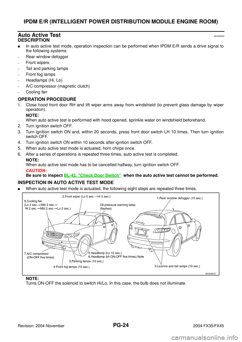
�In auto active test mode, operation inspection can be performed when IPDM E/R sends a drive signal to
the following systems:
–Rear window defogger
–Front wipers
–Tail and parking lamps
–Front fog lamps
–Headlamps (Hi, Lo)
–A/C compressor (magnetic clutch)
–Cooling fan
OPERATION PROCEDURE
1. Close hood front door RH and lift wiper arms away from windshield (to prevent glass damage by wiper
operation).
NOTE:
When auto active test is performed with hood opened, sprinkle water on windshield beforehand.
2. Turn ignition switch OFF.
3. Turn ignition switch ON and, within 20 seconds, press front door switch LH 10 times. Then turn ignition
switch OFF.
4. Turn ignition switch ON within 10 seconds after ignition switch OFF.
5. When auto active test mode is actuated, horn chirps once.
6. After a series of operations is repeated three times, auto active test is completed.
NOTE:
When auto active test mode has to be cancelled halfway, turn ignition switch OFF.
CAUTION:
Be sure to inspect BL-42, "
Check Door Switch" when the auto active test cannot be performed.
INSPECTION IN AUTO ACTIVE TEST MODE
�When auto active test mode is actuated, the following eight steps are repeated three times.
NOTE:
Turns ON-OFF the solenoid to switch Hi/Lo. In this case, the bulb does not illuminate.
SKIA4967E
Page 3863 of 4449
PG-28
IPDM E/R (INTELLIGENT POWER DISTRIBUTION MODULE ENGINE ROOM)
Revision: 2004 November 2004 FX35/FX45
IPDM E/R Power/Ground Circuit InspectionAKS007NW
1. CHECK FUSE AND FUSIBLE LINK
�Make sure the following fusible links or IPDM E/R fuses are not blown.
OK or NG
OK >> GO TO 2.
NG >> Replace fuse or fusible link.
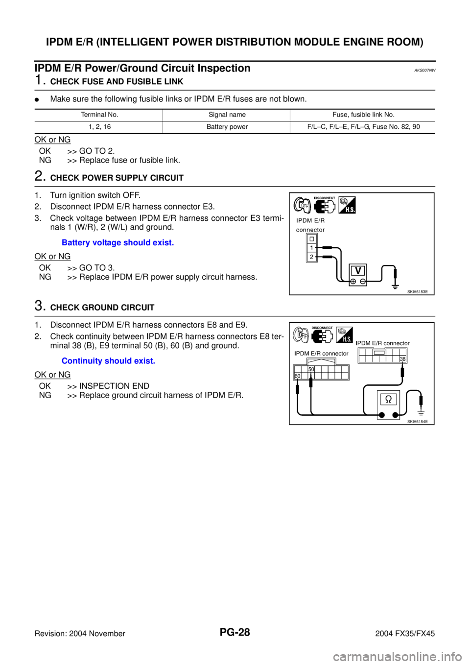
2. CHECK POWER SUPPLY CIRCUIT
1. Turn ignition switch OFF.
2. Disconnect IPDM E/R harness connector E3.
3. Check voltage between IPDM E/R harness connector E3 termi-
nals 1 (W/R), 2 (W/L) and ground.
OK or NG
OK >> GO TO 3.
NG >> Replace IPDM E/R power supply circuit harness.
3. CHECK GROUND CIRCUIT
1. Disconnect IPDM E/R harness connectors E8 and E9.
2. Check continuity between IPDM E/R harness connectors E8 ter-
minal 38 (B), E9 terminal 50 (B), 60 (B) and ground.
OK or NG
OK >> INSPECTION END
NG >> Replace ground circuit harness of IPDM E/R.
Terminal No. Signal name Fuse, fusible link No.
1, 2, 16 Battery power F/L–C, F/L–E, F/L–G, Fuse No. 82, 90
Battery voltage should exist.
SKIA6183E
Continuity should exist.
SKIA6184E
Page 3864 of 4449
IPDM E/R (INTELLIGENT POWER DISTRIBUTION MODULE ENGINE ROOM)
PG-29
C
D
E
F
G
H
I
J
L
MA
B
PG
Revision: 2004 November 2004 FX35/FX45
Inspection With CONSULT-II (Self-Diagnosis)AKS005SG
CAUTION:
If CONSULT-II is used with no connection of CONSULT-II CONVERTER, malfunctions might be
detected in self-diagnosis depending on control unit which carry out CAN communication.
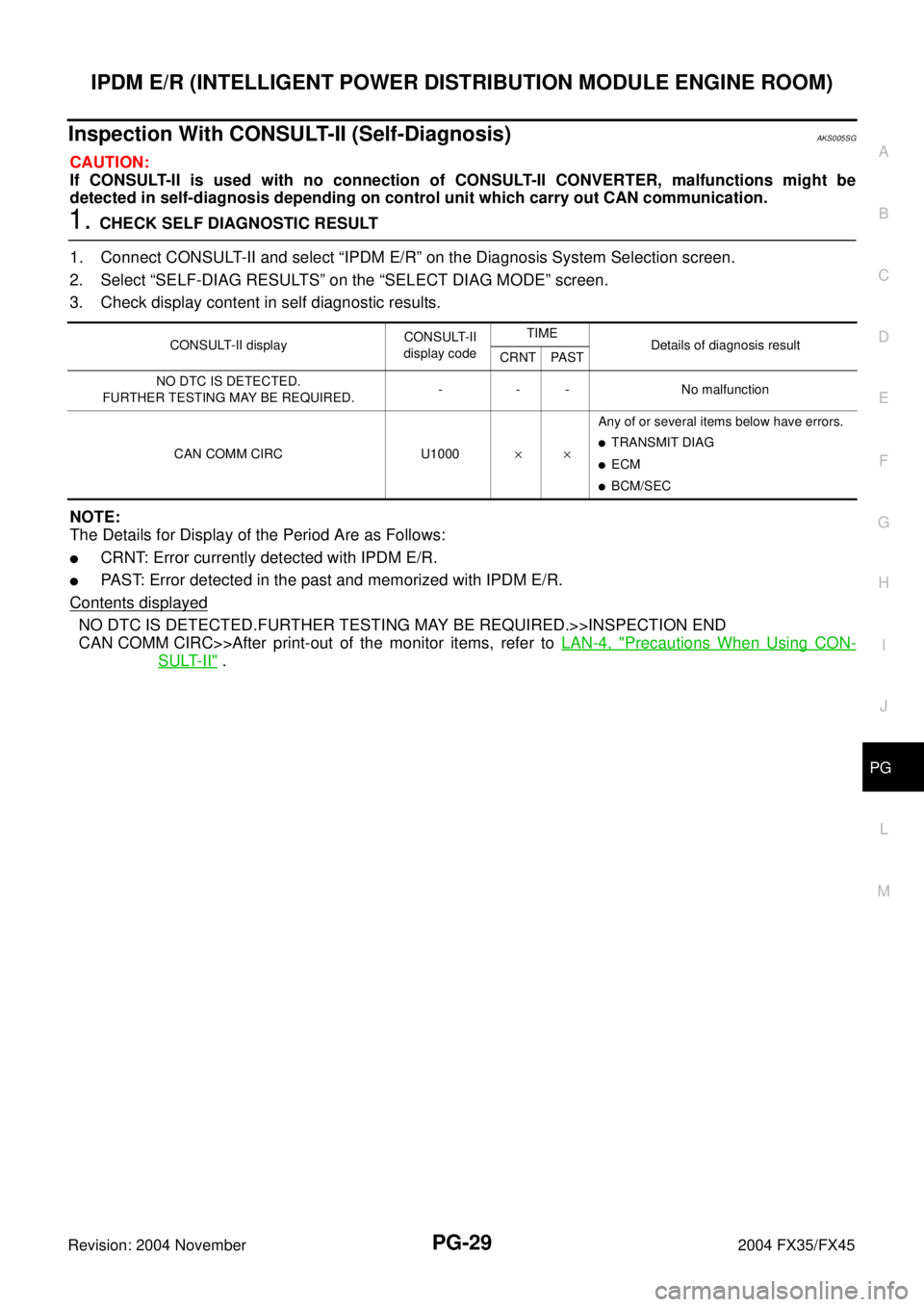
1. CHECK SELF DIAGNOSTIC RESULT
1. Connect CONSULT-II and select “IPDM E/R” on the Diagnosis System Selection screen.
2. Select “SELF-DIAG RESULTS” on the “SELECT DIAG MODE” screen.
3. Check display content in self diagnostic results.
NOTE:
The Details for Display of the Period Are as Follows:
�CRNT: Error currently detected with IPDM E/R.
�PAST: Error detected in the past and memorized with IPDM E/R.
Contents displayed
NO DTC IS DETECTED.FURTHER TESTING MAY BE REQUIRED.>>INSPECTION END
CAN COMM CIRC>>After print-out of the monitor items, refer to LAN-4, "
Precautions When Using CON-
SULT-II" .
CONSULT-II displayCONSULT-II
display codeTIME
Details of diagnosis result
CRNT PAST
NO DTC IS DETECTED.
FURTHER TESTING MAY BE REQUIRED.- - - No malfunction
CAN COMM CIRC U1000××Any of or several items below have errors.
�TRANSMIT DIAG
�ECM
�BCM/SEC
Page 3923 of 4449
PR-4
FRONT PROPELLER SHAFT
Revision: 2004 November 2004 FX35/FX45
FRONT PROPELLER SHAFTPFP:37200
On-Vehicle ServiceADS000KL
PROPELLER SHAFT VIBRATION
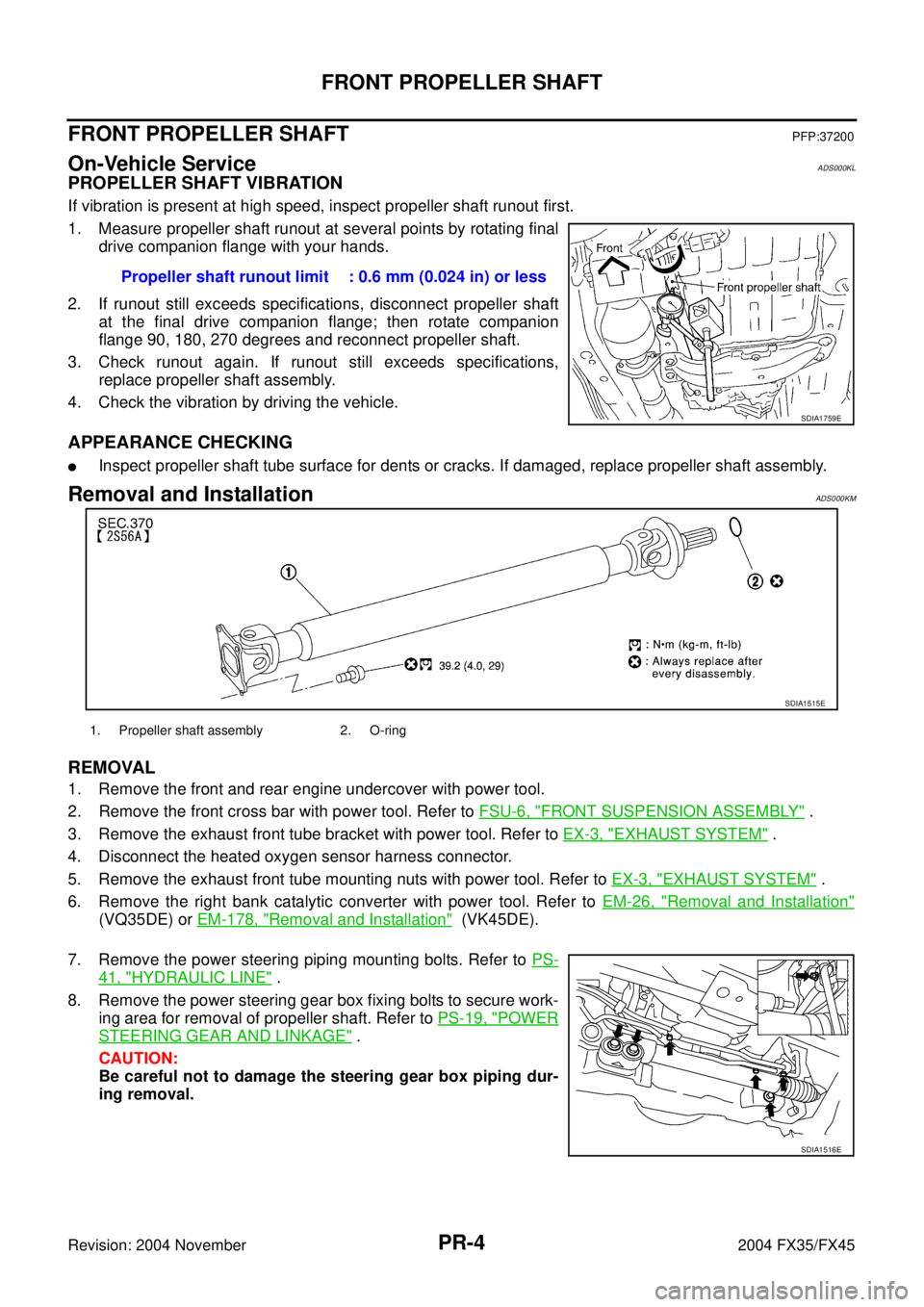
If vibration is present at high speed, inspect propeller shaft runout first.
1. Measure propeller shaft runout at several points by rotating final
drive companion flange with your hands.
2. If runout still exceeds specifications, disconnect propeller shaft
at the final drive companion flange; then rotate companion
flange 90, 180, 270 degrees and reconnect propeller shaft.
3. Check runout again. If runout still exceeds specifications,
replace propeller shaft assembly.
4. Check the vibration by driving the vehicle.
APPEARANCE CHECKING
�Inspect propeller shaft tube surface for dents or cracks. If damaged, replace propeller shaft assembly.
Removal and InstallationADS000KM
REMOVAL
1. Remove the front and rear engine undercover with power tool.
2. Remove the front cross bar with power tool. Refer to FSU-6, "
FRONT SUSPENSION ASSEMBLY" .
3. Remove the exhaust front tube bracket with power tool. Refer to EX-3, "
EXHAUST SYSTEM" .
4. Disconnect the heated oxygen sensor harness connector.
5. Remove the exhaust front tube mounting nuts with power tool. Refer to EX-3, "
EXHAUST SYSTEM" .
6. Remove the right bank catalytic converter with power tool. Refer to EM-26, "
Removal and Installation"
(VQ35DE) or EM-178, "Removal and Installation" (VK45DE).
7. Remove the power steering piping mounting bolts. Refer to PS-
41, "HYDRAULIC LINE" .
8. Remove the power steering gear box fixing bolts to secure work-
ing area for removal of propeller shaft. Refer to PS-19, "
POWER
STEERING GEAR AND LINKAGE" .
CAUTION:
Be careful not to damage the steering gear box piping dur-
ing removal.Propeller shaft runout limit : 0.6 mm (0.024 in) or less
SDIA1759E
SDIA1515E
1. Propeller shaft assembly 2. O-ring
SDIA1516E
Page 3924 of 4449
FRONT PROPELLER SHAFT
PR-5
C
E
F
G
H
I
J
K
L
MA
B
PR
Revision: 2004 November 2004 FX35/FX45
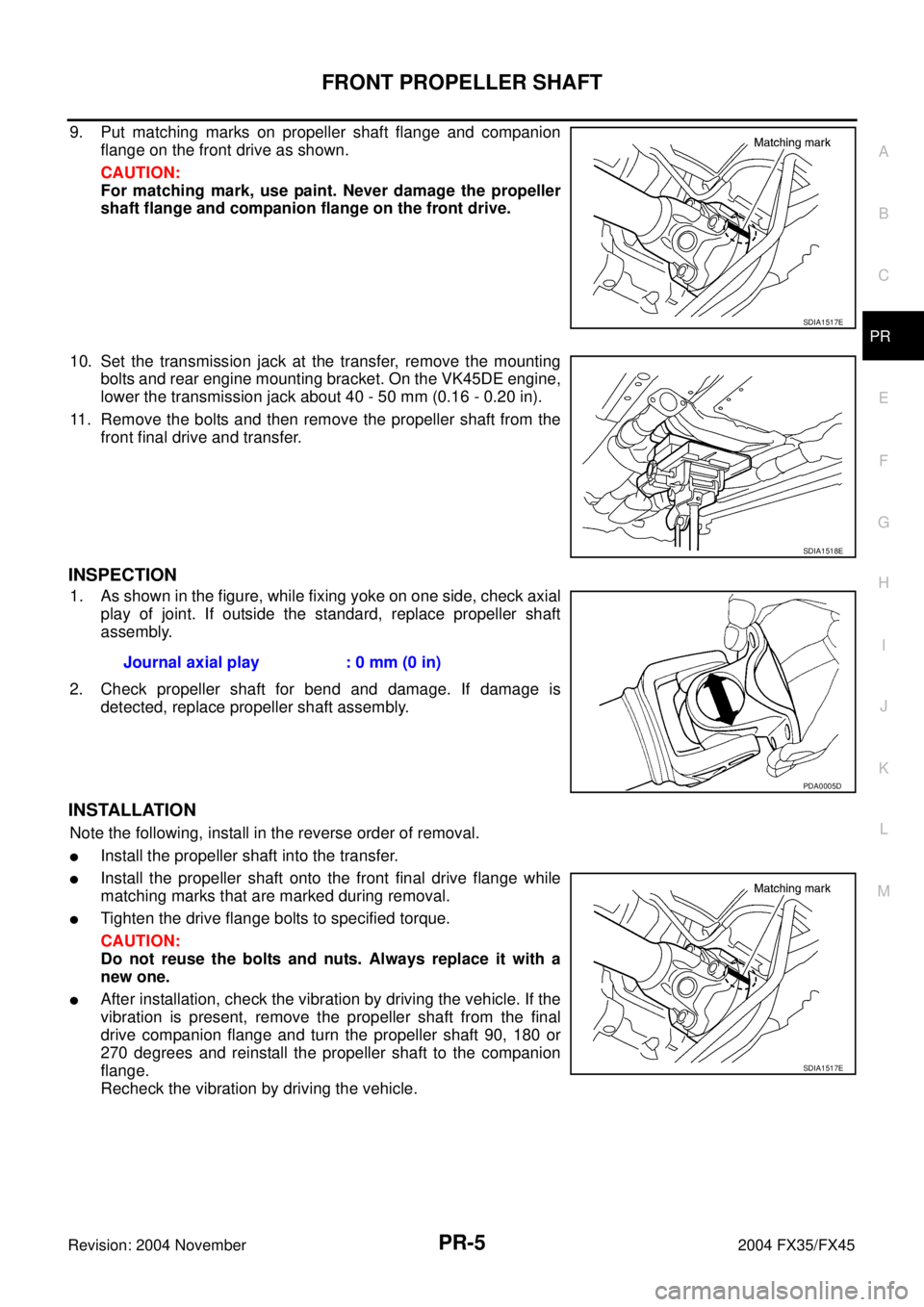
9. Put matching marks on propeller shaft flange and companion
flange on the front drive as shown.
CAUTION:
For matching mark, use paint. Never damage the propeller
shaft flange and companion flange on the front drive.
10. Set the transmission jack at the transfer, remove the mounting
bolts and rear engine mounting bracket. On the VK45DE engine,
lower the transmission jack about 40 - 50 mm (0.16 - 0.20 in).
11. Remove the bolts and then remove the propeller shaft from the
front final drive and transfer.
INSPECTION
1. As shown in the figure, while fixing yoke on one side, check axial
play of joint. If outside the standard, replace propeller shaft
assembly.
2. Check propeller shaft for bend and damage. If damage is
detected, replace propeller shaft assembly.
INSTALLATION
Note the following, install in the reverse order of removal.
�Install the propeller shaft into the transfer.
�Install the propeller shaft onto the front final drive flange while
matching marks that are marked during removal.
�Tighten the drive flange bolts to specified torque.
CAUTION:
Do not reuse the bolts and nuts. Always replace it with a
new one.
�After installation, check the vibration by driving the vehicle. If the
vibration is present, remove the propeller shaft from the final
drive companion flange and turn the propeller shaft 90, 180 or
270 degrees and reinstall the propeller shaft to the companion
flange.
Recheck the vibration by driving the vehicle.
SDIA1517E
SDIA1518E
Journal axial play : 0 mm (0 in)
PDA0005D
SDIA1517E
Page 3941 of 4449
PS-8
POWER STEERING FLUID
Revision: 2004 November 2004 FX35/FX45
POWER STEERING FLUIDPFP:KLF20
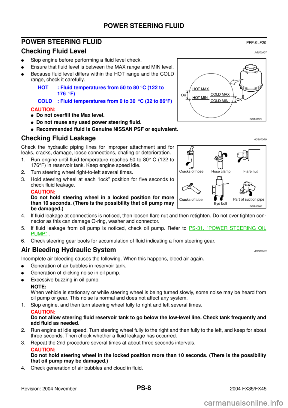
Checking Fluid LevelAGS000GT
�Stop engine before performing a fluid level check.
�Ensure that fluid level is between the MAX range and MIN level.
�Because fluid level differs within the HOT range and the COLD
range, check it carefully.
CAUTION:
�Do not overfill the Max level.
�Do not reuse any used power steering fluid.
�Recommended fluid is Genuine NISSAN PSF or equivalent.
Checking Fluid LeakageAGS000GU
Check the hydraulic piping lines for improper attachment and for
leaks, cracks, damage, loose connections, chafing or deterioration.
1. Run engine until fluid temperature reaches 50 to 80° C (122 to
176°F) in reservoir tank. Keep engine speed idle.
2. Turn steering wheel right-to-left several times.
3. Hold steering wheel at each “lock” position for five seconds to
check fluid leakage.
CAUTION:
Do not hold steering wheel in a locked position for more
than 10 seconds. (There is the possibility that oil pump may
be damaged.)
4. If fluid leakage at connections is noticed, then loosen flare nut and then retighten. Do not over tighten con-
nector as this can damage O-ring, washer and connector.
5. If fluid leakage from oil pump is noticed, check oil pump. Refer to PS-31, "
POWER STEERING OIL
PUMP" .
6. Check steering gear boots for accumulation of fluid indicating a from steering gear.
Air Bleeding Hydraulic SystemAGS000GV
Incomplete air bleeding causes the following. When this happens, bleed air again.
�Generation of air bubbles in reservoir tank.
�Generation of clicking noise in oil pump.
�Excessive buzzing in oil pump.
NOTE:
When vehicle is stationary or while steering wheel is being turned slowly, some noise may be heard from
oil pump or gear. This noise is normal and does not affect any system.
1. Stop engine, and then turn steering wheel fully to right and left several times.
CAUTION:
Do not allow steering fluid reservoir tank to go below the low-level line. Check tank frequently and
add fluid as needed.
2. Run engine at idle speed. Turn steering wheel fully to the right and then fully to the left, and keep for about
three seconds. Then check whether a fluid leakage has occurred.
3. Repeat the 2nd procedure several times at about three seconds intervals.
CAUTION:
Do not hold steering wheel in the locked position more than 10 seconds. (There is the possibility
that oil pump may be damaged.)
4. Check generation of air bubbles and cloud in fluid.HOT : Fluid temperatures from 50 to 80 °C (122 to
176°F)
COLD : Fluid temperatures from 0 to 30°C (32 to 86°F)
SGIA0232J
SGIA0506E
Page 3942 of 4449
POWER STEERING FLUID
PS-9
C
D
E
F
H
I
J
K
L
MA
B
PS
Revision: 2004 November 2004 FX35/FX45
5. If air bubbles and the cloud don't fade, stop engine, hold air bleeding until air bubbles and the cloud fade.
Perform the 2nd and the 3rd procedures again.
6. Stop engine, check fluid level.