Page 3996 of 4449
SERVICE DATA
RAX-15
C
E
F
G
H
I
J
K
L
MA
B
RAX
Revision: 2004 November 2004 FX35/FX45
SERVICE DATAPFP:00030
Wheel BearingADS000C9
Drive ShaftADS000KS
Axial end play0 mm (0 in)
Rotational torqueAt a load of 49,033 N (5,000 kg, 11,000 lb)
Less than 2.7 N·m (0.28 kg-m, 24 in-lb)
Measurement of spring scale Less than 26.6 N (2.7 kg, 5.95 lb)
Measuring point (Brake caliper installation points)
SDIA0801E
Joint Wheel side Final drive side
Engine model VQ35DE VK45DE VQ35DE VK45DE
Grease quantity86 − 96 g
(3.03 − 3.39 oz)140 − 160 g
(4.93 − 5.64 oz)124 − 134 g
(4.37 − 4.73 oz)175 − 195 g
(6.17 − 6.88 oz)
Boots installed length 97 mm (3.82 in) 141.5 mm (5.57 in) 93.9 mm (3.697 in) 147.9 mm (5.82 in)
Page 4064 of 4449

REAR SUSPENSION ASSEMBLY
RSU-5
C
D
F
G
H
I
J
K
L
MA
B
RSU
Revision: 2004 November 2004 FX35/FX45
REAR SUSPENSION ASSEMBLYPFP:55020
On-Vehicle Inspection and ServiceAES000MJ
Make sure the mounting conditions (looseness, back lash) of each component and component status (wear,
damage) are normal.
INSPECTION OF SUSPENSION ARM BALL JOINT END PLAY
Measure axial end play by installing and moving up/down between suspension arm and axle with an iron pry
bar or something similar.
CAUTION:
Be careful not to damage ball joint boot.
SHOCK ABSORBER INSPECTION
Check shock absorber for oil leakage, damage and replace if necessary.
Wheel Alignment InspectionAES000MK
DESCRIPTION
Measure wheel alignment under unladen conditions. “Unladen conditions” mean that fuel, engine coolant, and
lubricant are full. Spare tire, jack, hand tools and mats are in designated positions.
PRELIMINARY CHECK
1. Check tires for improper air pressure and wear.
2. Check road wheels for runout.
3. Check wheel bearing axial end play.
4. Check suspension arm ball joint axial end play.
5. Check shock absorber operation.
6. Check each mounting part of axle and suspension for looseness and deformation.
7. Check each link, arm and member for cracks, deformation, and other damage.
8. Check vehicle posture.
CAMBER INSPECTION
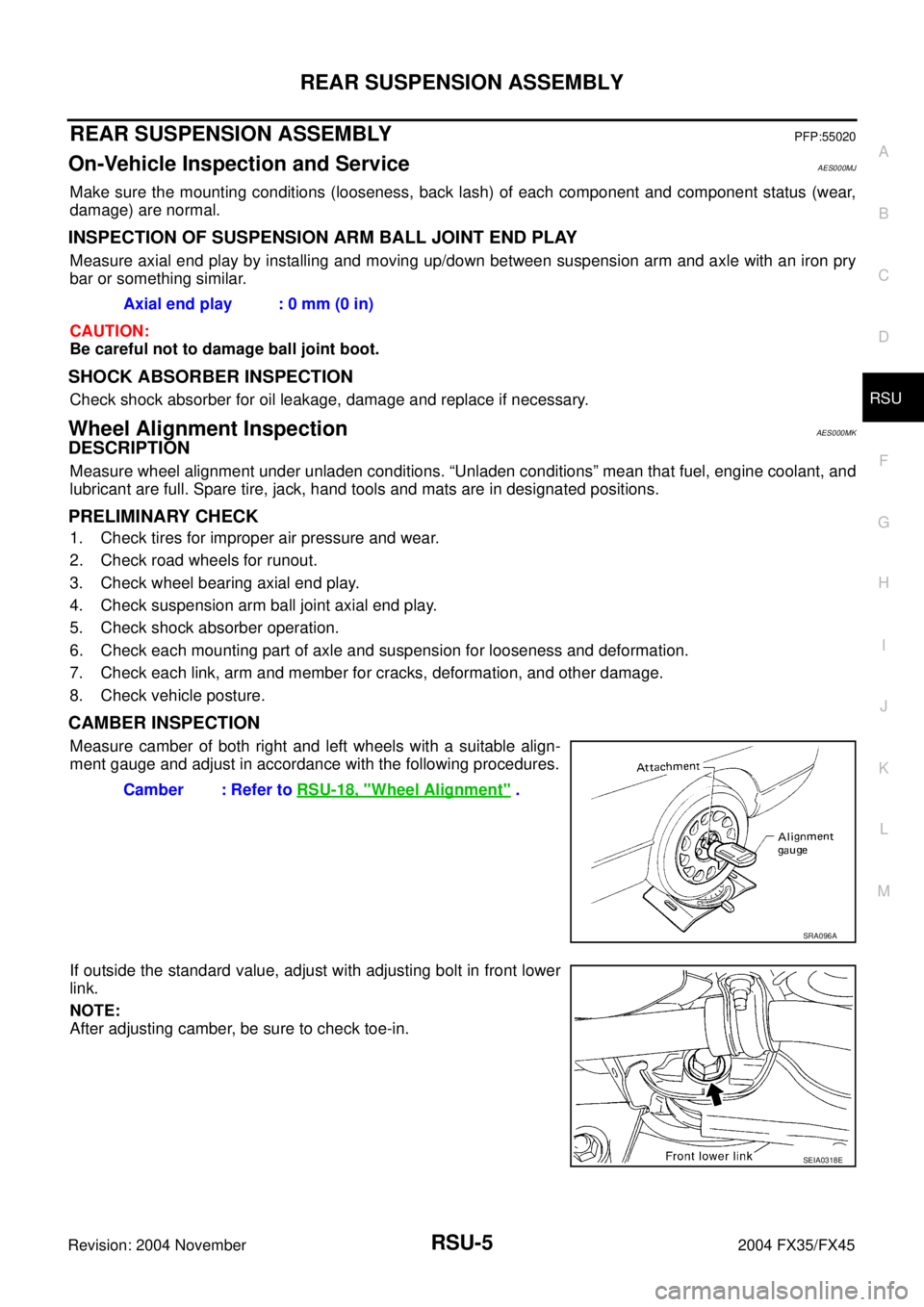
Measure camber of both right and left wheels with a suitable align-
ment gauge and adjust in accordance with the following procedures.
If outside the standard value, adjust with adjusting bolt in front lower
link.
NOTE:
After adjusting camber, be sure to check toe-in.Axial end play : 0 mm (0 in)
Camber : Refer to RSU-18, "
Wheel Alignment" .
SRA096A
SEIA0318E
Page 4070 of 4449

SUSPENSION ARM
RSU-11
C
D
F
G
H
I
J
K
L
MA
B
RSU
Revision: 2004 November 2004 FX35/FX45
SUSPENSION ARMPFP:55501
Removal and InstallationAES000MP
REMOVAL
1. Remove tire with power tool.
2. Remove stabilizer connecting rod mounting bracket from suspension arm with power tool.
3. Remove drive shaft from vehicle. (VK45DE models) Refer to RAX-9, "
Removal and Installation" .
4. Remove cotter pin of suspension arm ball joint, and loosen nut.
5. Use a ball joint remover (suitable tool) to remove suspension arm from axle. Be careful not to damage ball
joint boot.
CAUTION:
Tighten temporarily mounting nut to prevent damage to threads and to prevent ball joint remover
(suitable tool) from coming off.
6. Remove fixing nuts and bolts between suspension arm and rear suspension member with power tool.
7. Remove suspension arm from vehicle.
INSPECTION AFTER REMOVAL
Visual Inspection
�Check suspension arm and bushing for deformation, cracks, or damage. If any non-standard condition is
found, replace it.
�Check boot of ball joint for cracks, or damage, and also for grease leakage.
Ball Joint Inspection
Manually move ball stud to confirm it moves smoothly with no binding.
Swing Torque Inspection
NOTE:
Before measuring, move ball joint at least ten times by hand to check for smooth movement.
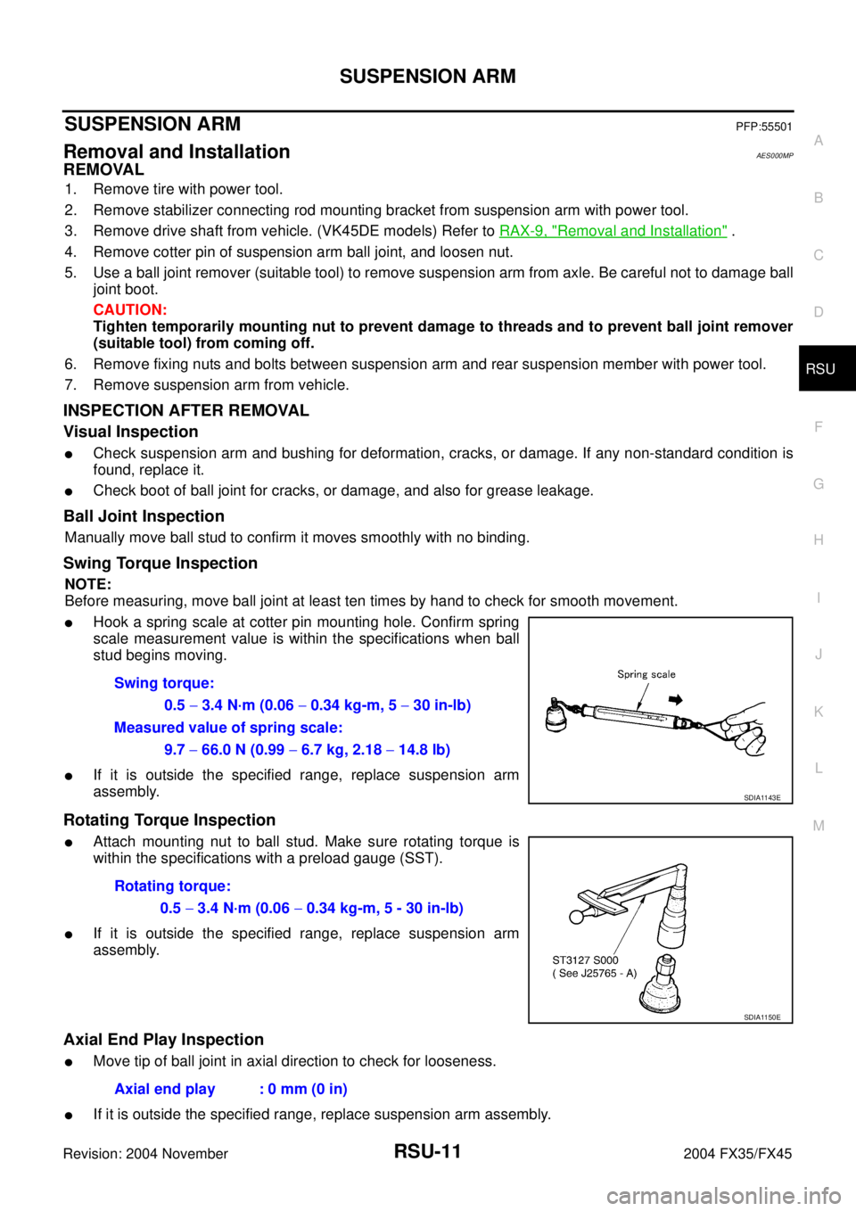
�Hook a spring scale at cotter pin mounting hole. Confirm spring
scale measurement value is within the specifications when ball
stud begins moving.
�If it is outside the specified range, replace suspension arm
assembly.
Rotating Torque Inspection
�Attach mounting nut to ball stud. Make sure rotating torque is
within the specifications with a preload gauge (SST).
�If it is outside the specified range, replace suspension arm
assembly.
Axial End Play Inspection
�Move tip of ball joint in axial direction to check for looseness.
�If it is outside the specified range, replace suspension arm assembly.Swing torque:
0.5 − 3.4 N·m (0.06 − 0.34 kg-m, 5 − 30 in-lb)
Measured value of spring scale:
9.7 − 66.0 N (0.99 − 6.7 kg, 2.18 − 14.8 lb)
SDIA1143E
Rotating torque:
0.5 − 3.4 N·m (0.06 − 0.34 kg-m, 5 - 30 in-lb)
SDIA1150E
Axial end play : 0 mm (0 in)