Page 1229 of 4449
CO-40
[VK45DE]
RADIATOR
Revision: 2004 November 2004 FX35/FX45
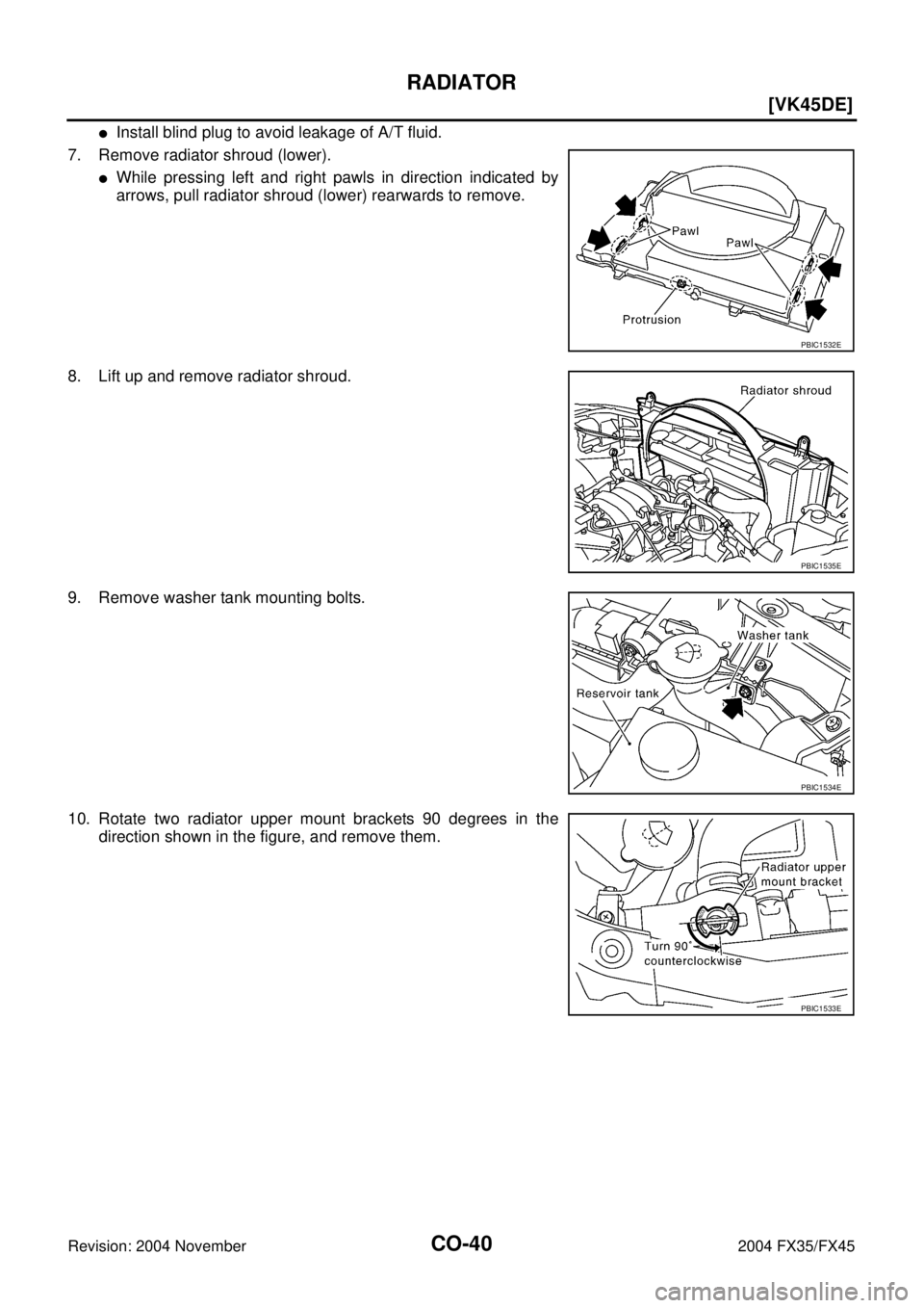
�Install blind plug to avoid leakage of A/T fluid.
7. Remove radiator shroud (lower).
�While pressing left and right pawls in direction indicated by
arrows, pull radiator shroud (lower) rearwards to remove.
8. Lift up and remove radiator shroud.
9. Remove washer tank mounting bolts.
10. Rotate two radiator upper mount brackets 90 degrees in the
direction shown in the figure, and remove them.
PBIC1532E
PBIC1535E
PBIC1534E
PBIC1533E
Page 1232 of 4449
RADIATOR (ALUMINUM TYPE)
CO-43
[VK45DE]
C
D
E
F
G
H
I
J
K
L
MA
CO
Revision: 2004 November 2004 FX35/FX45
RADIATOR (ALUMINUM TYPE)PFP:21460
Disassembly and AssemblyABS006JL
PREPARATION
1. Attach spacer to tip of radiator plate pliers A (SST).
Spacer specification: 1.5 mm (0.059 in) thick × 18 mm (0.71 in)
wide × 8.5 mm (0.335 in) long.
2. Make sure that when radiator plate pliers A [SST: KV99103510 ( — )] are closed dimension H′′ is
approx. 7.6 mm (0.299 in).
3. Adjust dimension H′′ with spacer, if necessary.
DISASSEMBLY
1. Remove upper and lower tanks with radiator plate pliers B
(SST).
1. Upper tank 2. Sealing rubber 3. Core
4. Lower tank 5. Conical washer 6. Washer
7. O-ring 8. Oil cooler
SBIA0449E
SLC655CB
SLC903-A
Page 1233 of 4449
CO-44
[VK45DE]
RADIATOR (ALUMINUM TYPE)
Revision: 2004 November 2004 FX35/FX45
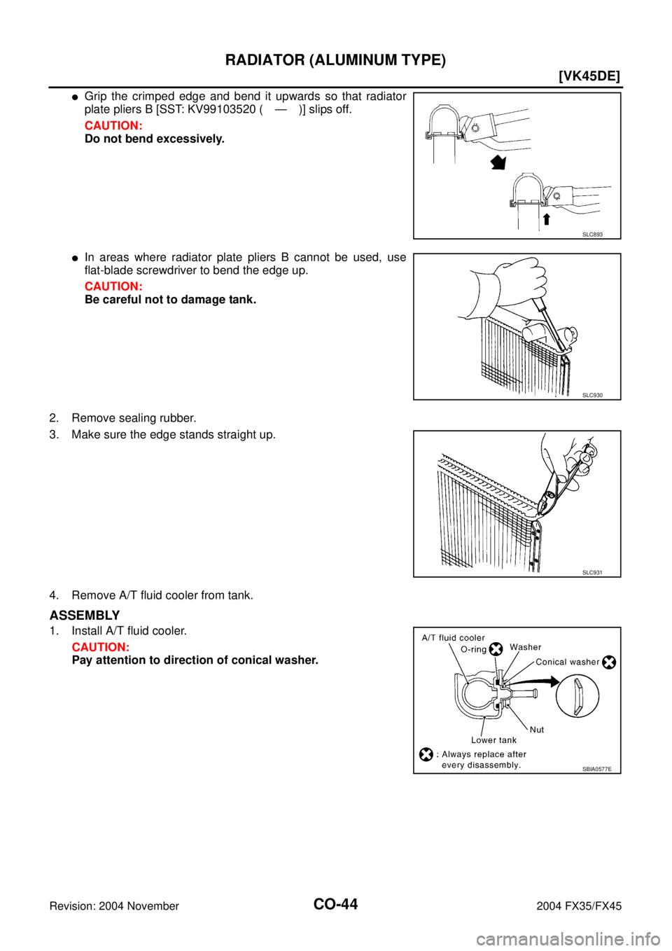
�Grip the crimped edge and bend it upwards so that radiator
plate pliers B [SST: KV99103520 ( — )] slips off.
CAUTION:
Do not bend excessively.
�In areas where radiator plate pliers B cannot be used, use
flat-blade screwdriver to bend the edge up.
CAUTION:
Be careful not to damage tank.
2. Remove sealing rubber.
3. Make sure the edge stands straight up.
4. Remove A/T fluid cooler from tank.
ASSEMBLY
1. Install A/T fluid cooler.
CAUTION:
Pay attention to direction of conical washer.
SLC893
SLC930
SLC931
SBIA0577E
Page 1234 of 4449
RADIATOR (ALUMINUM TYPE)
CO-45
[VK45DE]
C
D
E
F
G
H
I
J
K
L
MA
CO
Revision: 2004 November 2004 FX35/FX45
2. Clean contact portion of tank.
3. Install sealing rubber while pushing it with fingers.
CAUTION:
Be careful not to twist sealing rubber.
4. Caulk tank in numerical order as shown in the figure with radia-
tor plate pliers A (SST).
SLC932
SLC917A
SLC904-A
PBIC2076E
Page 1243 of 4449
CO-54
[VK45DE]
SERVICE DATA AND SPECIFICATIONS (SDS)
Revision: 2004 November 2004 FX35/FX45
SERVICE DATA AND SPECIFICATIONS (SDS)PFP:00030
Standard and LimitABS006JQ
ENGINE COOLANT CAPACITY (APPROXIMATE)
Unit: (US qt, Imp qt)
RADIATOR
Unit: kPa (kg/cm2 , psi)
THERMOSTAT
WATER CONTROL VALVE
Engine coolant capacity (With reservoir tank at “MAX” level) 10.0 (10-5/8, 8-3/4)
Reservoir tank engine coolant capacity (at “MAX” level) 0.8 (7/8, 3/4)
Radiator cap relief pressureStandard 78 - 98 (0.8 - 1.0, 11 - 14)
Limit 59 (0.6, 9)
Leakage test pressure 157 (1.6, 23)
Valve opening temperature 80 - 84°C (176 - 183°F)
Maximum valve lift More than 10 mm/ 95°C (0.39 in/ 203°F)
Valve closing temperature 77°C (171°F)
Valve opening temperature 93.5 - 96.5°C (200 - 206°F)
Maximum valve lift More than 8 mm/ 108°C (0.315 in/ 226°F)
Valve closing temperature 90°C (194°F)
Page 1249 of 4449

DI-6
COMBINATION METERS
Revision: 2004 November 2004 FX35/FX45
WATER TEMPERATURE GAUGE
The water temperature gauge indicates the engine coolant temperature.
ECM provides a water temperature signal to unified meter and A/C amp. with CAN communication line. Uni-
fied meter and A/C amp. provides a water temperature signal to combination meter for water temperature
gauge with communication line between unified meter and A/C amp. and combination meter.
TACHOMETER
The tachometer indicates engine speed in revolutions per minute (rpm).
ECM provides an engine speed signal to unified meter and A/C amp. with CAN communication line. Unified
meter and A/C amp. provides an engine speed signal to combination meter for tachometer with communica-
tion line between unified meter and A/C amp. and combination meter.
FUEL GAUGE
The fuel gauge indicates the approximate fuel level in the fuel tank.
The fuel gauge is regulated by a variable ground signal supplied
�from unified meter and A/C amp. terminal 36
�through the fuel level sensor unit and fuel pump (main) terminals 5 and 2, and
�through the fuel level sensor unit (sub) terminals 2 and 1
�to unified meter and A/C amp. terminal 28 for the fuel gauge.
Unified meter and A/C amp. provides an fuel level signal to combination meter for fuel gauge with communica-
tion line between unified meter and A/C amp. and combination meter.
SPEEDOMETER
ABS actuator and electric unit (control unit) provides a vehicle speed signal to the unified meter and A/C amp.
with CAN communication line. After unified meter and A/C amp. received the vehicle speed signal, it changes
the signal to 8 pulse signal and provides the 8 pulse signal to the combination meter for the speedometer.
Component Parts and Harness Connector LocationAKS005MI
SKIA4796E
Page 1263 of 4449

DI-20
COMBINATION METERS
Revision: 2004 November 2004 FX35/FX45
Fuel Level Sensor Signal Inspection 1AKS005MY
The following symptoms do not indicate a malfunction.
FUEL GAUGE
�Depending on vehicle position or driving circumstance, the fuel in the tank flows and the pointer may fluc-
tuate.
�If the vehicle is fueled with the ignition switch ON, the pointer will move slowly.
1. CHECK UNIFIED METER AND A/C AMP. INPUT SIGNAL
1. Select “METER A/C AMP” on CONSULT-II.
2. Using “FUEL METER” on “DATA MONIOR”, compare the value
of “DATA MONITOR” with fuel gauge pointer of combination
meter.
OK or NG
OK >> GO TO 2.
NG >> Replace combination meter.
2. CHECK FUEL LEVEL SENSOR
Check components. Refer to DI-25, "
CHECK FUEL LEVEL SENSOR UNIT" .
OK or NG
OK >> GO TO 3.
NG >> Replace fuel level sensor unit.
3. CHECK FUEL LEVEL SENSOR (SUB) CIRCUIT
1. Disconnect unified meter and A/C amp. connector and fuel level sensor unit (sub) connector.
2. Check continuity between unified meter and A/C amp. harness
connector M56 terminal 28 (W/B) and fuel level sensor unit (sub)
harness connector B40 terminal 1 (LG).
3. Check continuity between unified meter and A/C amp. harness
connector M56 terminal 28 (W/B) and ground.
OK or NG
OK >> GO TO 4.
NG >> Repair harness or connector.
Fuel gauge pointer Reference value of data monitor [lit.]
Full Approx. 86
Three quarters Applox. 70
Half Approx. 48
A quarter Approx. 25
Empty Approx. 9
PKIA2088E
Continuity should exist.
Continuity should not exist.
SKIA5203E
Page 1264 of 4449
 CIRCUIT
1. Disconnect fuel level sensor unit and fuel pump (main) conne")
COMBINATION METERS
DI-21
C
D
E
F
G
H
I
J
L
MA
B
DI
Revision: 2004 November 2004 FX35/FX45
4. CHECK FUEL LEVEL SENSOR (MAIN·SUB) CIRCUIT
1. Disconnect fuel level sensor unit and fuel pump (main) connector.
2. Check continuity between fuel level sensor unit (sub) harness
connector B40 terminal 2 (Y) and fuel level sensor unit and fuel
pump (main) harness connector B39 terminal 2 (Y).
3. Check continuity between fuel level sensor unit (sub) harness
connector B40 terminal 2 (Y) and ground.
OK or NG
OK >> GO TO 5.
NG >> Repair harness or connector.
5. CHECK FUEL LEVEL SENSOR (MAIN) CIRCUIT
1. Check continuity between fuel level sensor unit and fuel pump
(main) harness connector B39 terminal 5 (B) and unified meter
and A/C amp. harness connector M56 terminal 36 (B/W).
2. Check continuity between fuel level sensor unit and fuel pump
(main) harness connector B39 terminal 5 (B) and ground.
OK or NG
OK >> GO TO 6.
NG >> Repair harness or connector.
6. CHECK INSTALLATION CONDITION
Check fuel level sensor unit installation, and check whether the float arm interferes or binds with any of the
internal components in the fuel tank.
OK or NG
OK >> Replace unified meter and A/C amp. Refer to DI-34, "Removal and Installation of Unified Meter
and A/C Amp." .
NG >> Install the fuel level sensor unit properly.
Fuel Level Sensor Signal Inspection 2AKS005MZ
The following symptoms do not indicate a malfunction.
LOW-FUEL WARNING LAMP
Depending on vehicle position or driving circumstance, the fuel in the tank flows and the warning lamp ON tim-
ing may change.
1. CHECK FUEL GAUGE
Check if fuel gauge is normally operating.
YES >> Replace combination meter.
NO >> Go to DI-20, "
Fuel Level Sensor Signal Inspection 1" . Continuity should exist.
Continuity should not exist.
SKIA5204E
Continuity should exist.
Continuity should not exist.
SKIA5205E
![INFINITI FX35 2004 Service Manual RADIATOR (ALUMINUM TYPE)
CO-43
[VK45DE]
C
D
E
F
G
H
I
J
K
L
MA
CO
Revision: 2004 November 2004 FX35/FX45
RADIATOR (ALUMINUM TYPE)PFP:21460
Disassembly and AssemblyABS006JL
PREPARATION
1. Attach spacer](/manual-img/42/57021/w960_57021-1231.png "INFINITI FX35 2004 Service Manual RADIATOR (ALUMINUM TYPE)
CO-43
[VK45DE]
C
D
E
F
G
H
I
J
K
L
MA
CO
Revision: 2004 November 2004 FX35/FX45
RADIATOR (ALUMINUM TYPE)PFP:21460
Disassembly and AssemblyABS006JL
PREPARATION
1. Attach spacer")
![INFINITI FX35 2004 Service Manual RADIATOR (ALUMINUM TYPE)
CO-45
[VK45DE]
C
D
E
F
G
H
I
J
K
L
MA
CO
Revision: 2004 November 2004 FX35/FX45
2. Clean contact portion of tank.
3. Install sealing rubber while pushing it with fingers.
CAUT](/manual-img/42/57021/w960_57021-1233.png "INFINITI FX35 2004 Service Manual RADIATOR (ALUMINUM TYPE)
CO-45
[VK45DE]
C
D
E
F
G
H
I
J
K
L
MA
CO
Revision: 2004 November 2004 FX35/FX45
2. Clean contact portion of tank.
3. Install sealing rubber while pushing it with fingers.
CAUT")
![INFINITI FX35 2004 Service Manual CO-54
[VK45DE]
SERVICE DATA AND SPECIFICATIONS (SDS)
Revision: 2004 November 2004 FX35/FX45
SERVICE DATA AND SPECIFICATIONS (SDS)PFP:00030
Standard and LimitABS006JQ
ENGINE COOLANT CAPACITY (APPROXIMA](/manual-img/42/57021/w960_57021-1242.png "INFINITI FX35 2004 Service Manual CO-54
[VK45DE]
SERVICE DATA AND SPECIFICATIONS (SDS)
Revision: 2004 November 2004 FX35/FX45
SERVICE DATA AND SPECIFICATIONS (SDS)PFP:00030
Standard and LimitABS006JQ
ENGINE COOLANT CAPACITY (APPROXIMA")