Page 3039 of 4449
FFD-4
PREPARATION
Revision: 2004 November 2004 FX35/FX45
KV31100300 ( – )
Pin punch Removing and installing pinion mate shaft
lock pin
ST30032000 ( – )
A: 80mm (3.15 in) dia.
B: 38 mm (1.50 in) dia.
C: 31 mm (1.22 in) dia.
Inner race adaptorInstalling drive pinion bearing
Installing side shaft and retainer
KV38102510 ( – )
a: 71 mm (2.80 in) dia.
b: 65 mm (2.56 in) dia.
DriftInstalling front oil seal
ST33210000 ( – )
a: 44 mm (1.73 in) dia.
b: 34.5 mm (1.36 in) dia.
c: 22 mm (0.87 in) dia.
Drift
�Removing side shaft bearing
�Installing left side oil seal
ST37820000 ( – )
a: 39 mm (1.54 in) dia.
b: 72 mm (2.83 in) dia.
DriftInstalling drive pinion bearing
KV31103000 ( – )
a: 49 mm (1.93 in) dia.
b: 70 mm (2.76 in) dia.
DriftInstalling drive pinion bearing
ST1982000 ( – )
a: 70 mm (2.76 in) dia.
b: 50 mm (1.97 in) dia.
DriftInstalling side shaft oil seal Tool number (Kent-Moore No.)
Tool nameDescription
ZZA0515D
SDIA0217J
ZZA0838D
ZZA1046D
ZZA0836D
ZZA1113D
ZZA0838D
Page 3040 of 4449
PREPARATION
FFD-5
C
E
F
G
H
I
J
K
L
MA
B
FFD
Revision: 2004 November 2004 FX35/FX45
Commercial Service ToolsADS000N5
ST35321000 ( – )
a: 49 mm (1.93 in) dia.
b: 41 mm (1.61 in) dia.
DriftInstalling side bearing
KV40104000 ( – )
a: 85 mm (3.35 in) dia.
b: 65 mm (2.56 in) dia.
Drive pinion flange wrenchRemoving and installing drive pinion lock
nut
ST3127S000 (see J25765-A)
1. GG91030000
Torque wrench (J25765)
2. HT62940000 ( – )
Socket adapter (1/2″)
3. HT62900000 ( – )
Socket adapter (3/8″)
Preload gaugeInspecting pinion bearing preload and total
preload Tool number (Kent-Moore No.)
Tool nameDescription
ZZA1000D
NT659
NT124
Tool nameDescription
Power toolLoosening bolts and nuts
PBIC0190E
Page 3042 of 4449
FRONT OIL SEAL
FFD-7
C
E
F
G
H
I
J
K
L
MA
B
FFD
Revision: 2004 November 2004 FX35/FX45
FRONT OIL SEALPFP:38189
Removal and InstallationADS000N7
REMOVAL
1. Remove the front propeller shaft. Refer to PR-4, "REMOVAL" .
2. Put a matching mark on the end of the drive pinion correspond-
ing to the B position matching mark on the final drive companion
flange.
CAUTION:
�For matching mark, use paint. Never damage drive pin-
ion.
�The matching mark B on the final drive companion flange
indicates the maximum vertical runout position.
3. Using the drive pinion flange wrench.Remove drive pinion lock
nut with tool.
4. Remove the companion flange using puller (commercial service
tool)
5. Remove the front oil seal using outer race puller.
SDIA1609E
Tool number : KV40104000 ( – )
SDIA1647E
SDIA1642E
Tool number : ST33290001 (J34286)
SDIA1643E
Page 3043 of 4449
FFD-8
FRONT OIL SEAL
Revision: 2004 November 2004 FX35/FX45
INSTALLATION
1. Apply multi-purpose grease to sealing lips of the oil seal. Drive
the oil seal into the differential case using special service tool so
that the oil seal flush with the gear carrier end.
NOTE:
�When installing the front oil seal, be careful not to get it
inclined.
�Discard the old front oil seal. Always replace it with a new
one.
2. Install the companion flange while align the matching mark of
the drive pinion with the matching mark B of the companion
flange.
3. Apply oil to the drive pinion threads and the seating surface of
drive pinion lock nut.
4. Using the drive pinion flange wrench. Install drive pinion lock nut
with tool.
CAUTION:
Do not reuse the drive pinion lock nut. Always replace it
with a new one.
5. Install the front propeller shaft. Refer to PR-5, "
INSTALLATION"
.Tool number A : ST33400001 (J26082)
B : KV38102510 ( – )
SDIA1645E
SDIA1609E
Tool number : KV40104000 ( – )
SDIA1647E
Page 3050 of 4449
FRONT FINAL DRIVE ASSEMBLY
FFD-15
C
E
F
G
H
I
J
K
L
MA
B
FFD
Revision: 2004 November 2004 FX35/FX45
1. Washer 2. Carrier cover 3. Gear oil defence
4. Breather joint 5. Dowel pin 6. Drive pinion height adjusting washer
7. Drive pinion 8. Drive gear 9. Side bearing adjusting washer
10. Differential case 11. Side bearing 12. O-ring
13. Front oil seal 14. Side retainer 15. Side bearing adjusting shim
16. Air breather hose 17. Bushing 18. Breather tube
19. Companion flange 20. Drive pinion bearing 21. Drive pinion bearing adjusting
washer
22. Drive pinion adjusting washer 23. Extension tube retainer 24. Dust sealed
25. Side shaft 26. Extension tube 27. Carrier case
28. Side gear thrust washer 29. Lock pin 30. Pinion mate gear
31. Pinion mate thrust washer 32. Pinion mate shaft 33. Circlip
34. Side gear 35. Filler plug 36. Drain plug
37. Drive pinion lock nut 38. Side oil seal 39. Side shaft oil seal
40. Bearing
Page 3052 of 4449
FRONT FINAL DRIVE ASSEMBLY
FFD-17
C
E
F
G
H
I
J
K
L
MA
B
FFD
Revision: 2004 November 2004 FX35/FX45
7. Drive pinion 8. Drive gear 9. Side bearing adjusting washer
10. Differential case 11. Side bearing 12. O-ring
13. Front oil seal 14. Side retainer 15. Side bearing adjusting shim
16. Air breather hose 17. Bushing 18. Breather tube
19. Companion flange 20. Drive pinion bearing 21. Drive pinion bearing adjusting
washer
22. Drive pinion adjusting washer 23. Extension tube retainer 24. Dust sealed
25. Side shaft 26. Extension tube 27. Carrier case
28. Side gear thrust washer 29. Lock pin 30. Pinion mate gear
31. Pinion mete thrust washer 32. Pinion mate shaft 33. Circlip
34. Side gear 35. Filler plug 36. Drain plug
37. Drive pinion lock nut 38. Side oil seal 39. Side shaft oil seal
40. Bearing
Page 3057 of 4449

FFD-22
FRONT FINAL DRIVE ASSEMBLY
Revision: 2004 November 2004 FX35/FX45
REMOVAL OF DRIVE PINION ASSEMBLY
1. Hold the companion flange using cam sprocket wrench or flange wrench, remove the pinion lock nut.
2. Remove the companion flange using puller.
3. Temporarily install drive pinion lock nut.
CAUTION:
Install the drive pinion lock nut until it flash with the drive
pinion end.
4. Remove the drive pinion from the carrier case.
5. Remove the bearing outer race by tapping the race evenly.
6. On companion flange side, remove the bearing outer race with
bearing and oil seal.
7. Press out the drive pinion bearing from the drive pinion using
puller.
DIFFERENTIAL CASE DISASSEMBLY
1. Remove side bearing inner race.
To prevent damage to bearing, engage puller jaws in groove.
CAUTION:
�To prevent damage to the side bearing and drive gear,
place copper plates between these parts and vise.
�If is not necessary to remove side bearing except it is
replaced.Tool number : KV40104000 ( – )
Tool number : ST30031000 (J22912–01 )
SDIA1658E
SDIA1663E
Tool number
A: ST3305S001 (−)
B: ST33061000(J8107−2)
SPD920
Page 3058 of 4449
FRONT FINAL DRIVE ASSEMBLY
FFD-23
C
E
F
G
H
I
J
K
L
MA
B
FFD
Revision: 2004 November 2004 FX35/FX45
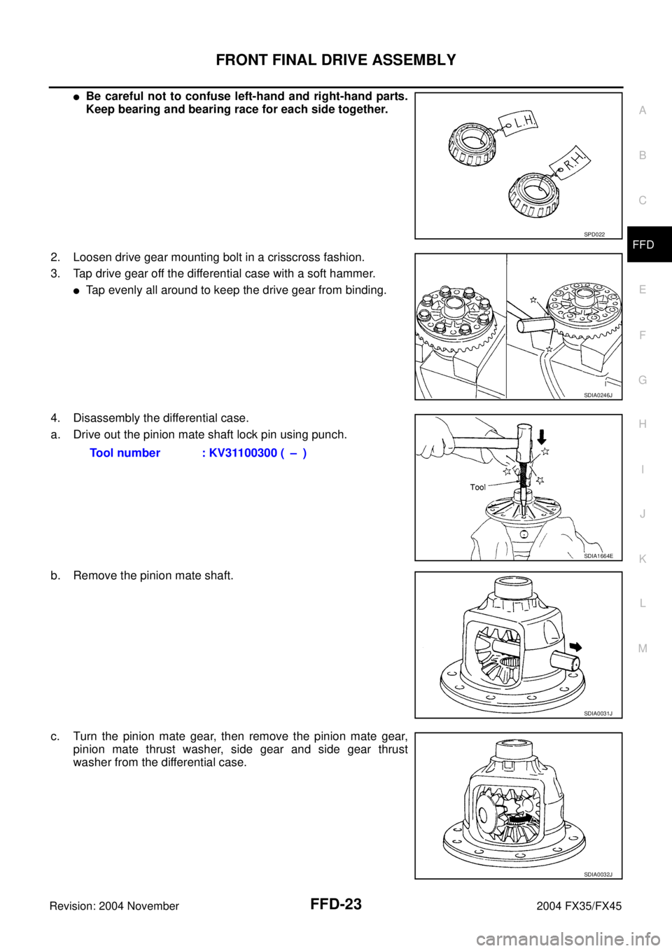
�Be careful not to confuse left-hand and right-hand parts.
Keep bearing and bearing race for each side together.
2. Loosen drive gear mounting bolt in a crisscross fashion.
3. Tap drive gear off the differential case with a soft hammer.
�Tap evenly all around to keep the drive gear from binding.
4. Disassembly the differential case.
a. Drive out the pinion mate shaft lock pin using punch.
b. Remove the pinion mate shaft.
c. Turn the pinion mate gear, then remove the pinion mate gear,
pinion mate thrust washer, side gear and side gear thrust
washer from the differential case.
SPD022
SDIA0246J
Tool number : KV31100300 ( – )
SDIA1664E
SDIA0031J
SDIA0032J

Pin punch Removing and installing pinion mate shaft
lock pin
ST30032000 ( – )
A: 80mm (3.15 in) dia.
B: 38 mm (1.50 in) d")

a: 49 mm (1.93 in) dia.
b: 41 mm (1.61 in) dia.
DriftInstalling")