Page 3060 of 4449

FRONT FINAL DRIVE ASSEMBLY
FFD-25
C
E
F
G
H
I
J
K
L
MA
B
FFD
Revision: 2004 November 2004 FX35/FX45
3. Install the side gear, thrust washers, pinion mate gears and
thrust washers to differential case.
CAUTION:
Install the circlip equipped side gear to the side retainer
side.
4. Install pinion mate gears by placing the pair of gear facing each
other, and turning them.
5. Install the pinion mate shaft while aligning the lock pin holes
between the differential case and pinion mate shaft.
6. Place the differential gear case so that measurement point fac-
ing up as shown.
7. Use two feeler gauges to prevent leaning of side gear as shown.
8. Measure the clearance at 3 points by turning the side gear.
9. Select side gear thrust washer so that the clearance is within
standard.
CAUTION:
Check the smooth gear movement.
10. Place the differential gear case upside down, and measure the
opposite side clearance.
SDIA0194J
SDIA0195J
SDIA1650E
Rear face of side gear and differential case clearance
: 0.20 mm (0.0079 in) or less
SDIA1654E
SDIA1655E
Page 3061 of 4449
FFD-26
FRONT FINAL DRIVE ASSEMBLY
Revision: 2004 November 2004 FX35/FX45
11. If clearance exceed limit, adjust the clearance by selecting adjusting shim.
�If clearance too large, increase thrust washer thickness.
�If clearance too small, decrease thrust washer thickness.
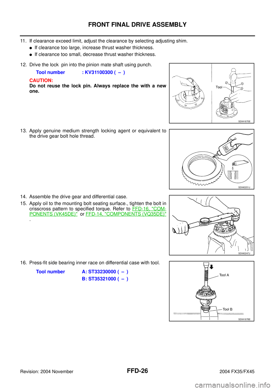
12. Drive the lock pin into the pinion mate shaft using punch.
CAUTION:
Do not reuse the lock pin. Always replace the with a new
one.
13. Apply genuine medium strength locking agent or equivalent to
the drive gear bolt hole thread.
14. Assemble the drive gear and differential case.
15. Apply oil to the mounting bolt seating surface., tighten the bolt in
crisscross pattern to specified torque. Refer to FFD-16, "
COM-
PONENTS (VK45DE)" or FFD-14, "COMPONENTS (VQ35DE)"
.
16. Press-fit side bearing inner race on differential case with tool.Tool number : KV31100300 ( – )
SDIA1670E
SDIA0201J
SDIA0247J
Tool number A: ST33230000 ( – )
B: ST35321000 ( – )
SDIA1678E
Page 3063 of 4449

FFD-28
FRONT FINAL DRIVE ASSEMBLY
Revision: 2004 November 2004 FX35/FX45
CAUTION:
Do not install the drive pinion adjusting washer and drive pinion bearing adjusting washer at this
time.
c. Install the companion flange without installing oil seal.
d. Apply oil drive pinion lock nut threads and seating surface, then temporarily install it.
e. Tighten the drive pinion lock nut until it reach standard preload.
CAUTION:
Tighten the drive pinion nut by very small degrees until the
specified preload in achieved. Do not tighten nut more than
necessary.
DIFFERENTIAL CASE INSTALLATION
1. Drive side bearing outer race into the carrier case with tool.
CAUTION:
Do not apply excessive force to the race.
2. Drive side bearing outer race into the side retainer with tool.
3. Apply oil to the bearing portion.
4. Install the deferential case assembly to the carrier case.
CAUTION:
Be careful not to damage the carrier cover mating surface.
5. Install the side bearing adjusting shim to the side retainer, tighten the bolt to specified torque.
CAUTION:
Install removed adjusting shim or same thickness shim.
NOTE:
Do not install O-ring.Tool number : KV40104000(−)
Pinion bearing preload without oil seal
: 0.78 - 1.57 N·m (0.08 - 0.16 kg-m, 7 - 13 in-lb)
SDIA1669E
Tool number : KV31103000 ( – )
SDIA1680E
Tool number : KV31103000 ( – )
SDIA1679E
Page 3068 of 4449

FRONT FINAL DRIVE ASSEMBLY
FFD-33
C
E
F
G
H
I
J
K
L
MA
B
FFD
Revision: 2004 November 2004 FX35/FX45
TOTAL PRELOAD INSPECTION
1. Turn companion flange in both directions 20 times or more to set
bearing rollers, then check total preload with special service tool.
�If the preload value is out of standard, adjust by changing side
bearing adjusting shim thickness (side retainer side).
–If preload value too large, increase the side bearing adjusting
shim thickness.
–If preload value too small, decrease the side bearing adjusting shim thickness.
DRIVE PINION PRELOAD ADJUSTMENT
Removal of differential case assembly
1. Unfasten the retainer tab using a flat blade screwdriver.
2. Remove the retainer by pulling it and tapping carrier case using a plastic hammer.
3. Remove the differential case assembly from the carrier case.
CAUTION:
Be careful not to damage the carrier cover mating surface.
Removal of drive pinon assembly
1. Hold the companion flange using cam sprocket wrench or flange
wrench, remove the drive pinion lock nut.
2. Remove the companion flange using puller.
3. Temporarily install drive pinion lock nut.
CAUTION:
Avoid damaging drive pinion threads, install the drive pinion lock nut unit it flash with drive pinion
end.
4. Remove the drive pinion from the carrier case using a copper hammer.
Preload Adjustment
1. Install drive pinion adjusting washer and drive pinion bearing adjusting washer onto the drive pinion, then
install drive pinion into the carrier case.
CAUTION:
Install the removed pinion height adjusting washer and drive pinion bearing adjusting washer or
same thickness washers to drive pinion.
2. Apply gear oil to the bearing portion.
3. Install drive pinion and drive pinion bearing into the carrier case.
4. Install the companion flange without installing oil seal.
5. Apply oil to drive pinion nut threads and seating surface, then temporarily install it.
6. Turn companion flange several times to seat the bearing.
7. Tighten the drive pinion nut while measuring preload using preload gauge.
8. Select drive pinion adjusting washer and drive pinion bearing adjusting washer so that standard preload is
obtain when the drive pinion nut is tightened to specified torque.Tool number : ST3127S000 (see J25765-A)
Total preload (without oil seal)
: 1.56 - 2.65 N·m
(0.16 - 0.27 kg-m, 14 - 23 in-lb)
SDIA1649E
Tool number : KV40104000 (−)
SDIA1658E
Page 3069 of 4449

FFD-34
FRONT FINAL DRIVE ASSEMBLY
Revision: 2004 November 2004 FX35/FX45
CAUTION:
�Tighten the drive pinion nut by very small degrees until the specified preload in achieved. Do
not tighten nut more than necessary.
�First select the thicker washer, then gradually select thinner one.
�Do not apply preload more than necessary.
Reassembly of drive pinion assembly
1. The standard preload is obtain when the drive pinion nut is tightened to specified toque, remove the pin-
ion.
2. Remove the companion flange using puller.
3. Drive out the drive pinion from carrier case using copper hammer.
4. Apply gear oil to bearing portion.
5. Install the drive pinion with selected drive pinion adjusting washer and drive pinion bearing adjusting
washer into the carrier case, then install bearing.
6. Apply multi-purpose grease to oil seal lips.
7. Drive oil seal into the final drive using drift.
8. Install companion flange.
9. Apply oil to new drive pinion lock nut threads and seating sur-
face, then install it onto the drive pinion.
CAUTION:
Do not reuse drive pinion lock nut. Always replace nut with
new one.
10. Turn the companion flange more than 20 times to seat bearing.
11. Tighten the drive pinion lock nut to specified torque.
CAUTION:
Do not overtighten the nut.
12. Measure the preload using preload gauge.Drive pinion lock nut torque : 186.2 N·m (19 kg-m, 137 ft-lb)
Pinion bearing preload without oil seal : 0.78 - 1.57 N·m (0.08 - 0.16 kg-m, 7 - 13 in-lb)
When the washer thickness is increased : Preload will decrease.
When the washer thickness is decreased : Preload will increase.
Tool number A: ST33400001 (J26082)
B: KV38102510 ( – )
SDIA1681E
Tool number : KV40104000 (−)
SDIA1669E
Tool number : ST3127S000 (see J25765-A)
Pinion bearing preload without oil seal
: 0.78 - 1.57 N·m (0.08 - 0.16 kg-m, 7 - 13 in-lb)
SDIA1649E
Page 3078 of 4449
FUEL LEVEL SENSOR UNIT, FUEL FILTER AND FUEL PUMP ASSEMBLY
FL-5
C
D
E
F
G
H
I
J
K
L
MA
FL
Revision: 2004 November 2004 FX35/FX45
3. Open fuel filler lid.
4. Open filler cap and release the pressure inside fuel tank.
5. Remove rear seat cushion. Refer to SE-107, "
REAR SEAT" .
6. Peel off floor carpet, then remove inspection hole cover for main
and sub fuel level sensor units by turning clips clockwise by 90
degrees.
7. Disconnect harness connector and fuel feed tube.
Disconnect quick connector as follows:
�Hold the sides of connector, push in tabs and pull out tube.
�If quick connector sticks to tube of main fuel level sensor unit,
push and pull quick connector several times until they start to
move.Then disconnect them by pulling.
PBIC1576E
PBIC1577E
SFE562A
Page 3081 of 4449
, then check connections for leaks by apply")
FL-8
FUEL LEVEL SENSOR UNIT, FUEL FILTER AND FUEL PUMP ASSEMBLY
Revision: 2004 November 2004 FX35/FX45
1. Turn ignition switch “ON” (with engine stopped), then check connections for leaks by applying fuel pres-
sure to fuel piping.
2. Start engine and let it idle and make sure there are no fuel leaks at the fuel system connections.
Disassembly and AssemblyABS005Z0
CAUTION:
Sub fuel level sensor unit cannot be disassembled and should be replaced as a unit.
DISASSEMBLY
Remove fuel level sensor unit as follows.
1. Disconnect harness connector.
�Hold connector by fingers and pull it out, because there is no
stopper release tab.
2. Using suitable tool, pull up tabs points as shown in the figure
(two points) to release the lock.
CAUTION:
Be careful not to damage it.
3. After fixing tabs are disengaged, slide fuel level sensor unit out
in direction shown by the arrow.
CAUTION:
Do not disassemble fuel filter and fuel pump assembly.
1. Fuel level sensor unit 2. Fuel filter and fuel pump assembly
PBIC1081E
PBIC1078E
PBIC1654E
PBIC1080E
Page 3094 of 4449

FRONT SUSPENSION ASSEMBLY
FSU-9
C
D
F
G
H
I
J
K
L
MA
B
FSU
Revision: 2004 November 2004 FX35/FX45
Removal and InstallationAES000N6
REMOVAL
1. Set an engine slinger to engine, then suspend engine.
2. Remove tire from vehicle with power tool.
3. Remove brake caliper with power tool. Hang it in a place where it will not interfere with work. Refer to BR-
20, "FRONT DISC BRAKE" .
4. Remove brake hose lock plate. Then remove brake hose from
strut assembly.
5. Remove disc rotor.
6. Remove wheel sensor harness from strut assembly.
CAUTION:
Do not pull on wheel sensor harness.
7. Remove undercover with power tool.
8. Remove front cross bar.
9. Remove steering hydraulic piping bracket from front suspension
member. Refer to PS-41, "
HYDRAULIC LINE" .
10. Remove cotter pin at steering outer socket, then loosen mount-
ing nut.
11. Use a ball joint remover (SST) to remove steering outer socket
from steering knuckle. Be careful not to damage ball joint boot.
CAUTION:
Tighten temporarily mounting nut to prevent damage to
threads and to prevent ball joint remover (SST) from com-
ing off.
12. Remove mounting bolts of steering gear with power tool, then
hang steering gear on vehicle. Refer to PS-19, "
POWER
STEERING GEAR AND LINKAGE" .
13. Remove front final drive side of drive shaft with power tool. (For
AWD models) Refer to FAX-12, "
Removal and Installation (Left
Side)" , FA X - 1 3 , "Removal and Installation (Right Side)" .
14. Set jack under front suspension member.
15. Remove fixing bolts and nuts between strut assembly and steering knuckle with power tool.
1. Strut upper plate 2. Strut spacer 3. Mounting insulator
4. Mounting insulator bracket 5. Mounting bearing 6. Spring upper seat
7. Spring upper rubber seat 8. Coil spring 9. Spring lower rubber seat
10. Bound bumper 11. Strut 12. Steering knuckle
13. Front suspension member 14. Transverse link 15. Stabilizer bar
16. Stabilizer bushing 17. Stabilizer clamp 18. Stabilizer connecting rod
19. Front cross bar 20. Cotter pin
SEIA0328E
SEIA0329E
SDIA1434E