Page 2615 of 4449
EC-1274
[VK45DE]
INJECTOR CIRCUIT
Revision: 2004 November 2004 FX35/FX45
INJECTOR CIRCUITPFP:16600
Component DescriptionABS00CEO
The fuel injector is a small, precise solenoid valve. When the ECM
supplies a ground to the injector circuit, the coil in the injector is
energized. The energized coil pulls the ball valve back and allows
fuel to flow through the injector into the intake manifold. The amount
of fuel injected depends upon the injection pulse duration. Pulse
duration is the length of time the injector remains open. The ECM
controls the injection pulse duration based on engine fuel needs.
CONSULT-II Reference Value in Data Monitor ModeABS00CEP
Specification data are reference values.
SEF375Z
MONITOR ITEM CONDITION SPECIFICATION
B/FUEL SCHDL See EC-780, "
TROUBLE DIAGNOSIS - SPECIFICATION VALUE" .
INJ PULSE-B1
INJ PULSE-B2
�Engine: After warming up
�Air conditioner switch: OFF
�Shift lever: N
�No loadIdle 2.3 - 2.9 msec
2,000 rpm 2.3 - 2.9 msec
Page 2620 of 4449
INJECTOR CIRCUIT
EC-1279
[VK45DE]
C
D
E
F
G
H
I
J
K
L
MA
EC
Revision: 2004 November 2004 FX35/FX45
6. DETECT MALFUNCTIONING PART
Check the following.
�Harness connectors F21, F201
�Harness connectors F41, F221
�Harness for open or short between injector and ECM
>> Repair open circuit or short to ground or short to power in harness or connectors.
7. CHECK INJECTOR
Refer to EC-1279, "
Component Inspection" .
OK or NG
OK >> GO TO 8.
NG >> Replace injector.
8. CHECK INTERMITTENT INCIDENT
Refer to EC-784, "
TROUBLE DIAGNOSIS FOR INTERMITTENT INCIDENT" .
>>INSPECTION END
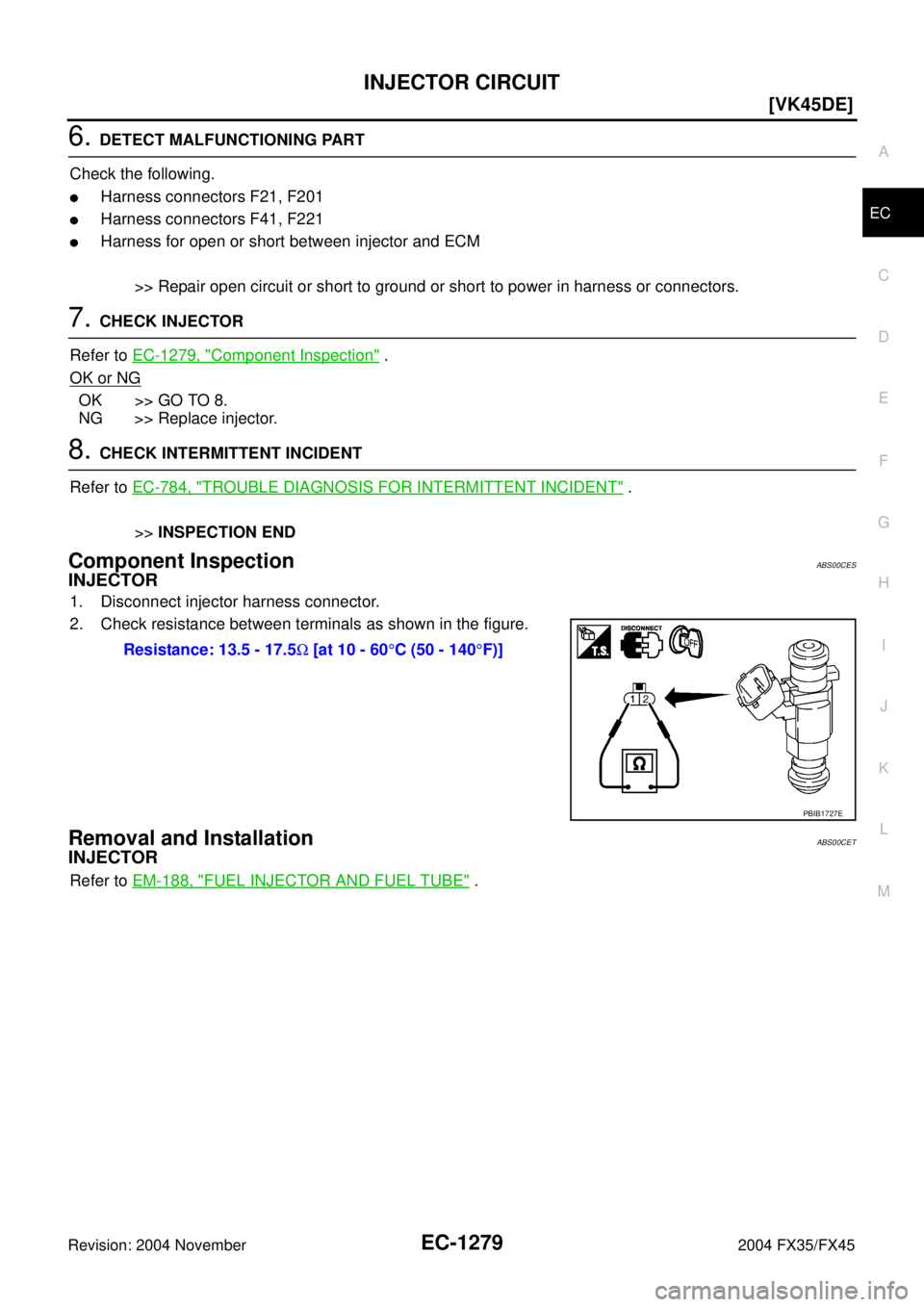
Component InspectionABS00CES
INJECTOR
1. Disconnect injector harness connector.
2. Check resistance between terminals as shown in the figure.
Removal and InstallationABS00CET
INJECTOR
Refer to EM-188, "FUEL INJECTOR AND FUEL TUBE" . Resistance: 13.5 - 17.5Ω [at 10 - 60°C (50 - 140°F)]
PBIB1727E
Page 2621 of 4449
![INFINITI FX35 2004 Service Manual EC-1280
[VK45DE]
FUEL PUMP CIRCUIT
Revision: 2004 November 2004 FX35/FX45
FUEL PUMP CIRCUITPFP:17042
DescriptionABS00CEU
SYSTEM DESCRIPTION
*: ECM determines the start signal status by the signals of](/manual-img/42/57021/w960_57021-2620.png "INFINITI FX35 2004 Service Manual EC-1280
[VK45DE]
FUEL PUMP CIRCUIT
Revision: 2004 November 2004 FX35/FX45
FUEL PUMP CIRCUITPFP:17042
DescriptionABS00CEU
SYSTEM DESCRIPTION
*: ECM determines the start signal status by the signals of")
EC-1280
[VK45DE]
FUEL PUMP CIRCUIT
Revision: 2004 November 2004 FX35/FX45
FUEL PUMP CIRCUITPFP:17042
DescriptionABS00CEU
SYSTEM DESCRIPTION
*: ECM determines the start signal status by the signals of engine speed and battery voltage.
The ECM activates the fuel pump for several seconds after the ignition switch is turned ON to improve engine
startability. If the ECM receives a engine speed signal from the camshaft position sensor (PHASE), it knows
that the engine is rotating, and causes the pump to operate. If the engine speed signal is not received when
the ignition switch is ON, the engine stalls. The ECM stops pump operation and prevents battery discharging,
thereby improving safety. The ECM does not directly drive the fuel pump. It controls the ON/OFF fuel pump
relay, which in turn controls the fuel pump.
COMPONENT DESCRIPTION
A turbine type design fuel pump is used in the fuel tank.
CONSULT-II Reference Value in Data Monitor ModeABS00CEV
Specification data are reference values.
Sensor Input signal to ECM ECM Function Actuator
Crankshaft position sensor (POS)
Camshaft position sensor (PHASE)Engine speed*
Fuel pump control Fuel pump relay
Battery Battery voltage*
Condition Fuel pump operation
Ignition switch is turned to ON Operates for 1 second.
Engine running and crankingOperates.
When engine is stoppedStops in 1.5 seconds.
Except as shown aboveSto ps.
PBIB1508E
MONITOR ITEM CONDITION SPECIFICATION
FUEL PUMP RLY
�For 1 second after turning ignition switch ON
�Engine running or crankingON
�Except above conditions OFF
Page 2622 of 4449
FUEL PUMP CIRCUIT
EC-1281
[VK45DE]
C
D
E
F
G
H
I
J
K
L
MA
EC
Revision: 2004 November 2004 FX35/FX45
Wiring DiagramABS00CEW
TBWH0112E
Page 2623 of 4449
![INFINITI FX35 2004 Service Manual EC-1282
[VK45DE]
FUEL PUMP CIRCUIT
Revision: 2004 November 2004 FX35/FX45
Specification data are reference values and are measured between each terminal and ground.
CAUTION:
Do not use ECM ground term](/manual-img/42/57021/w960_57021-2622.png "INFINITI FX35 2004 Service Manual EC-1282
[VK45DE]
FUEL PUMP CIRCUIT
Revision: 2004 November 2004 FX35/FX45
Specification data are reference values and are measured between each terminal and ground.
CAUTION:
Do not use ECM ground term")
EC-1282
[VK45DE]
FUEL PUMP CIRCUIT
Revision: 2004 November 2004 FX35/FX45
Specification data are reference values and are measured between each terminal and ground.
CAUTION:
Do not use ECM ground terminals when measuring input/output voltage. Doing so may result in dam-
age to the ECM's transistor. Use a ground other than ECM terminals, such as the ground.
Diagnostic ProcedureABS00CEX
1. CHECK OVERALL FUNCTION
1. Turn ignition switch ON.
2. Pinch fuel feed hose with two fingers.
Fuel pressure pulsation should be felt on the fuel feed hose
for 1 second after ignition switch is turned ON.
OK or NG
OK >>INSPECTION END
NG >> GO TO 2.
2. CHECK FUEL PUMP POWER SUPPLY CIRCUIT-I
1. Turn ignition switch OFF.
2. Disconnect ECM harness connector.
3. Turn ignition switch ON.
4. Check voltage between ECM terminal 113 and ground with
CONSULT-II or tester.
OK or NG
OK >> GO TO 5.
NG >> GO TO 3.
TER-
MINAL
NO.WIRE
COLORITEM CONDITION DATA (DC Voltage)
11 3 G Y / R F u e l p u m p r e l a y[Ignition switch: ON]
�For 1 second after turning ignition switch ON
[Engine is running]0 - 1.5V
[Ignition switch: ON]
�More than 1 second after turning ignition
switch ONBATTERY VOLTAGE
(11 - 14V)
PBIB1491E
Voltage: Battery voltage
PBIB1187E
Page 2624 of 4449
![INFINITI FX35 2004 Service Manual FUEL PUMP CIRCUIT
EC-1283
[VK45DE]
C
D
E
F
G
H
I
J
K
L
MA
EC
Revision: 2004 November 2004 FX35/FX45
3. CHECK FUEL PUMP POWER SUPPLY CIRCUIT-II
1. Turn ignition switch OFF.
2. Disconnect IPDM E/R harne](/manual-img/42/57021/w960_57021-2623.png "INFINITI FX35 2004 Service Manual FUEL PUMP CIRCUIT
EC-1283
[VK45DE]
C
D
E
F
G
H
I
J
K
L
MA
EC
Revision: 2004 November 2004 FX35/FX45
3. CHECK FUEL PUMP POWER SUPPLY CIRCUIT-II
1. Turn ignition switch OFF.
2. Disconnect IPDM E/R harne")
FUEL PUMP CIRCUIT
EC-1283
[VK45DE]
C
D
E
F
G
H
I
J
K
L
MA
EC
Revision: 2004 November 2004 FX35/FX45
3. CHECK FUEL PUMP POWER SUPPLY CIRCUIT-II
1. Turn ignition switch OFF.
2. Disconnect IPDM E/R harness connector E8.
3. Turn ignition switch ON.
4. Check voltage between IPDM E/R terminal 40 and ground with
CONSULT-II or tester.
OK or NG
OK >> GO TO 4.
NG >> GO TO 14.
4. DETECT MALFUNCTIONING PART
Check the following.
�Harness connectors E211, M41
�Harness for open or short between IPDM E/R and ECM
>> Repair open circuit or short to ground or short to power in harness or connectors.
5. CHECK CONDENSER POWER SUPPLY CIRCUIT-I
1. Turn ignition switch OFF.
2. Reconnect all harness connectors disconnected.
3. Disconnect condenser harness connector.
4. Turn ignition switch ON.
5. Check voltage between condenser terminal 1 and ground with
CONSULT-II or tester.
6. Also check harness for short to ground and short to power.
OK or NG
OK >> GO TO 9.
NG >> GO TO 6.Voltage: Battery voltage
PBIB1926E
PBIB1533E
Voltage: Battery voltage should exist for 1 sec-
ond after ignition switch is turned ON.
PBIB0624E
Page 2625 of 4449
![INFINITI FX35 2004 Service Manual EC-1284
[VK45DE]
FUEL PUMP CIRCUIT
Revision: 2004 November 2004 FX35/FX45
6. CHECK 15A FUSE
1. Turn ignition switch OFF.
2. Disconnect 15A fuse.
3. Check 15A fuse.
OK or NG
OK >> GO TO 7.
NG >> Replac](/manual-img/42/57021/w960_57021-2624.png "INFINITI FX35 2004 Service Manual EC-1284
[VK45DE]
FUEL PUMP CIRCUIT
Revision: 2004 November 2004 FX35/FX45
6. CHECK 15A FUSE
1. Turn ignition switch OFF.
2. Disconnect 15A fuse.
3. Check 15A fuse.
OK or NG
OK >> GO TO 7.
NG >> Replac")
EC-1284
[VK45DE]
FUEL PUMP CIRCUIT
Revision: 2004 November 2004 FX35/FX45
6. CHECK 15A FUSE
1. Turn ignition switch OFF.
2. Disconnect 15A fuse.
3. Check 15A fuse.
OK or NG
OK >> GO TO 7.
NG >> Replace fuse.
7. CHECK CONDENSER POWER SUPPLY CIRCUIT-II
1. Disconnect IPDM E/R harness connector E8.
2. Check harness continuity between IPDM E/R terminal 39 and condenser terminal 1.
Refer to Wiring Diagram.
3. Also check harness for short to ground and short to power.
OK or NG
OK >> GO TO 14.
NG >> GO TO 8.
8. DETECT MALFUNCTIONING PART
Check the following.
�Harness connectors E206, B6
�Harness for open or short between IPDM E/R and condenser
>> Repair harness or connectors.
9. CHECK CONDENSER GROUND CIRCUIT FOR OPEN AND SHORT
1. Check harness continuity between condenser terminal 2 and ground.
Refer to Wiring Diagram.
2. Also check harness for short to power.
OK or NG
OK >> GO TO 10.
NG >> Repair open circuit or short to power in harness or connectors.
10. CHECK CONDENSER
Refer to EC-1285, "
Component Inspection" .
OK or NG
OK >> GO TO 11.
NG >> Replace condenser.Continuity should exist.
Continuity should exist.
Page 2626 of 4449
![INFINITI FX35 2004 Service Manual FUEL PUMP CIRCUIT
EC-1285
[VK45DE]
C
D
E
F
G
H
I
J
K
L
MA
EC
Revision: 2004 November 2004 FX35/FX45
11 . CHECK FUEL PUMP POWER SUPPLY AND GROUND CIRCUIT FOR OPEN AND SHORT
1. Turn ignition switch OFF](/manual-img/42/57021/w960_57021-2625.png "INFINITI FX35 2004 Service Manual FUEL PUMP CIRCUIT
EC-1285
[VK45DE]
C
D
E
F
G
H
I
J
K
L
MA
EC
Revision: 2004 November 2004 FX35/FX45
11 . CHECK FUEL PUMP POWER SUPPLY AND GROUND CIRCUIT FOR OPEN AND SHORT
1. Turn ignition switch OFF")
FUEL PUMP CIRCUIT
EC-1285
[VK45DE]
C
D
E
F
G
H
I
J
K
L
MA
EC
Revision: 2004 November 2004 FX35/FX45
11 . CHECK FUEL PUMP POWER SUPPLY AND GROUND CIRCUIT FOR OPEN AND SHORT
1. Turn ignition switch OFF.
2. Disconnect “fuel level sensor unit and fuel pump” harness con-
nector.
3. Disconnect harness connector E206, B6.
4. Check harness continuity between “fuel level sensor unit and
fuel pump” terminal 1 and harness connector B6 terminal 4, “fuel
level sensor unit and fuel pump” terminal 3 and ground.
Refer to Wiring Diagram.
5. Also check harness for short to ground and short to power.
OK or NG
OK >> GO TO 13.
NG >> GO TO 12.
12. DETECT MALFUNCTIONING PART
Check the following.
�Harness connector B6
�Harness for open or short between “fuel level sensor unit and fuel pump” and harness connector B6
�Harness for open or short between “fuel level sensor unit and fuel pump” and ground
>> Repair open circuit or short to ground or short to power in harness or connectors.
13. CHECK FUEL PUMP
Refer to EC-1285, "
Component Inspection" .
OK or NG
OK >> GO TO 14.
NG >> Replace fuel pump.
14. CHECK INTERMITTENT INCIDENT
Refer to EC-784, "
TROUBLE DIAGNOSIS FOR INTERMITTENT INCIDENT" .
OK or NG
OK >> Replace IPDM E/R.
NG >> Repair or replace harness or connectors.
Component InspectionABS00CEY
FUEL PUMP
1. Disconnect “fuel level sensor unit and fuel pump” harness connector.
2. Check resistance between “fuel level sensor unit and fuel pump”
terminals 1 and 3.Continuity should exist.
PBIB1507E
Resistance: Approximately 0.2 - 5.0Ω [at 25°C (77°F)]
SEC918C
![INFINITI FX35 2004 Service Manual EC-1274
[VK45DE]
INJECTOR CIRCUIT
Revision: 2004 November 2004 FX35/FX45
INJECTOR CIRCUITPFP:16600
Component DescriptionABS00CEO
The fuel injector is a small, precise solenoid valve. When the ECM
supp](/manual-img/42/57021/w960_57021-2614.png "INFINITI FX35 2004 Service Manual EC-1274
[VK45DE]
INJECTOR CIRCUIT
Revision: 2004 November 2004 FX35/FX45
INJECTOR CIRCUITPFP:16600
Component DescriptionABS00CEO
The fuel injector is a small, precise solenoid valve. When the ECM
supp")
![INFINITI FX35 2004 Service Manual FUEL PUMP CIRCUIT
EC-1281
[VK45DE]
C
D
E
F
G
H
I
J
K
L
MA
EC
Revision: 2004 November 2004 FX35/FX45
Wiring DiagramABS00CEW
TBWH0112E](/manual-img/42/57021/w960_57021-2621.png "INFINITI FX35 2004 Service Manual FUEL PUMP CIRCUIT
EC-1281
[VK45DE]
C
D
E
F
G
H
I
J
K
L
MA
EC
Revision: 2004 November 2004 FX35/FX45
Wiring DiagramABS00CEW
TBWH0112E")