Page 4064 of 4449
REAR SUSPENSION ASSEMBLY
RSU-5
C
D
F
G
H
I
J
K
L
MA
B
RSU
Revision: 2004 November 2004 FX35/FX45
REAR SUSPENSION ASSEMBLYPFP:55020
On-Vehicle Inspection and ServiceAES000MJ
Make sure the mounting conditions (looseness, back lash) of each component and component status (wear,
damage) are normal.
INSPECTION OF SUSPENSION ARM BALL JOINT END PLAY
Measure axial end play by installing and moving up/down between suspension arm and axle with an iron pry
bar or something similar.
CAUTION:
Be careful not to damage ball joint boot.
SHOCK ABSORBER INSPECTION
Check shock absorber for oil leakage, damage and replace if necessary.
Wheel Alignment InspectionAES000MK
DESCRIPTION
Measure wheel alignment under unladen conditions. “Unladen conditions” mean that fuel, engine coolant, and
lubricant are full. Spare tire, jack, hand tools and mats are in designated positions.
PRELIMINARY CHECK
1. Check tires for improper air pressure and wear.
2. Check road wheels for runout.
3. Check wheel bearing axial end play.
4. Check suspension arm ball joint axial end play.
5. Check shock absorber operation.
6. Check each mounting part of axle and suspension for looseness and deformation.
7. Check each link, arm and member for cracks, deformation, and other damage.
8. Check vehicle posture.
CAMBER INSPECTION
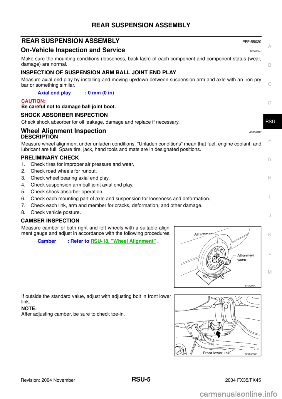
Measure camber of both right and left wheels with a suitable align-
ment gauge and adjust in accordance with the following procedures.
If outside the standard value, adjust with adjusting bolt in front lower
link.
NOTE:
After adjusting camber, be sure to check toe-in.Axial end play : 0 mm (0 in)
Camber : Refer to RSU-18, "
Wheel Alignment" .
SRA096A
SEIA0318E
Page 4077 of 4449
RSU-18
SERVICE DATA
Revision: 2004 November 2004 FX35/FX45
SERVICE DATAPFP:00030
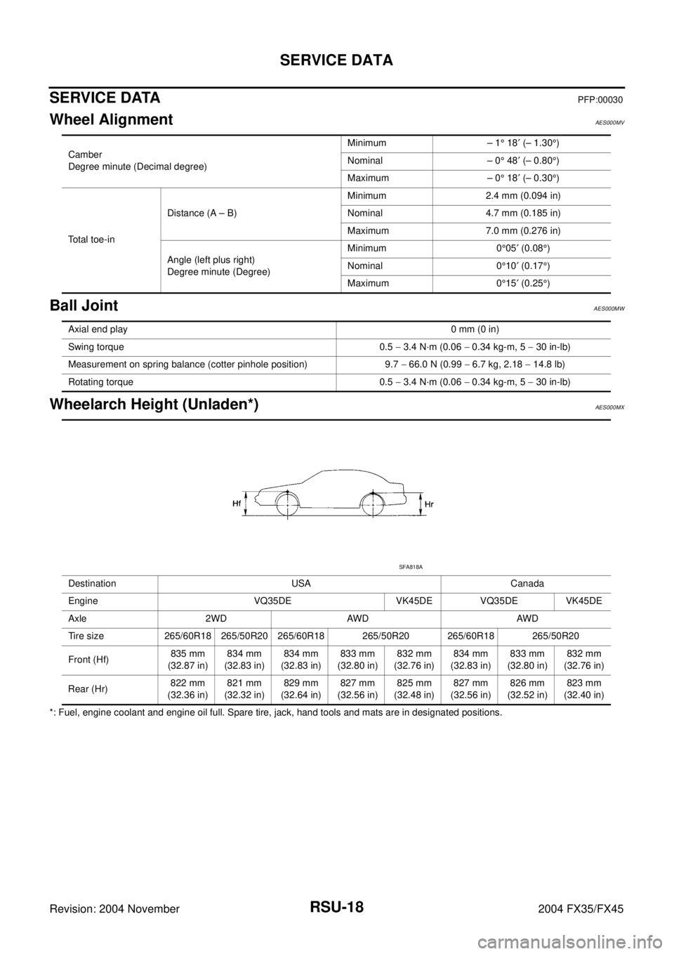
Wheel AlignmentAES000MV
Ball JointAES000MW
Wheelarch Height (Unladen*)AES000MX
*: Fuel, engine coolant and engine oil full. Spare tire, jack, hand tools and mats are in designated positions.Camber
Degree minute (Decimal degree)Minimum – 1° 18′ (– 1.30°)
Nominal – 0° 48′ (– 0.80°)
Maximum – 0° 18′ (– 0.30°)
Total toe-inDistance (A – B)Minimum 2.4 mm (0.094 in)
Nominal 4.7 mm (0.185 in)
Maximum 7.0 mm (0.276 in)
Angle (left plus right)
Degree minute (Degree)Minimum 0°05′ (0.08°)
Nominal 0°10′ (0.17°)
Maximum 0°15′ (0.25°)
Axial end play0 mm (0 in)
Swing torque 0.5 − 3.4 N·m (0.06 − 0.34 kg-m, 5 − 30 in-lb)
Measurement on spring balance (cotter pinhole position) 9.7 − 66.0 N (0.99 − 6.7 kg, 2.18 − 14.8 lb)
Rotating torque 0.5 − 3.4 N·m (0.06 − 0.34 kg-m, 5 − 30 in-lb)
Destination USA Canada
Engine VQ35DE VK45DE VQ35DE VK45DE
Axle 2WD AWD AWD
Tire size 265/60R18 265/50R20 265/60R18 265/50R20 265/60R18 265/50R20
Front (Hf)835 mm
(32.87 in)834 mm
(32.83 in)834 mm
(32.83 in)833 mm
(32.80 in)832 mm
(32.76 in)834 mm
(32.83 in)833 mm
(32.80 in)832 mm
(32.76 in)
Rear (Hr)822 mm
(32.36 in)821 mm
(32.32 in)829 mm
(32.64 in)827 mm
(32.56 in)825 mm
(32.48 in)827 mm
(32.56 in)826 mm
(32.52 in)823 mm
(32.40 in)
SFA818A
Page 4104 of 4449
STARTING SYSTEM
SC-15
C
D
E
F
G
H
I
J
L
MA
B
SC
Revision: 2004 November 2004 FX35/FX45
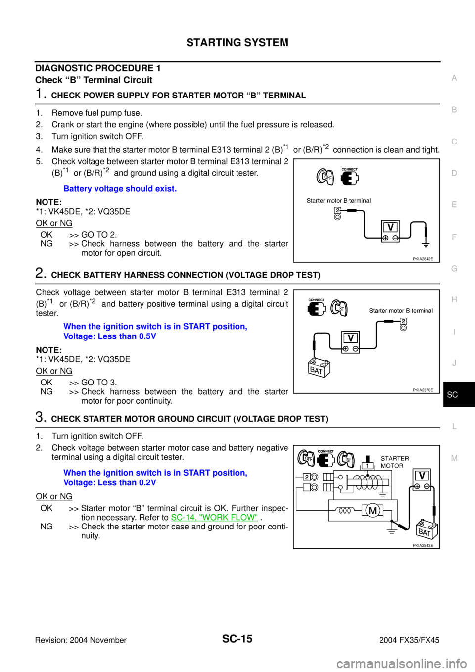
DIAGNOSTIC PROCEDURE 1
Check “B” Terminal Circuit
1. CHECK POWER SUPPLY FOR STARTER MOTOR “B” TERMINAL
1. Remove fuel pump fuse.
2. Crank or start the engine (where possible) until the fuel pressure is released.
3. Turn ignition switch OFF.
4. Make sure that the starter motor B terminal E313 terminal 2 (B)
*1 or (B/R)*2 connection is clean and tight.
5. Check voltage between starter motor B terminal E313 terminal 2
(B)
*1 or (B/R)*2 and ground using a digital circuit tester.
NOTE:
*1: VK45DE, *2: VQ35DE
OK or NG
OK >> GO TO 2.
NG >> Check harness between the battery and the starter
motor for open circuit.
2. CHECK BATTERY HARNESS CONNECTION (VOLTAGE DROP TEST)
Check voltage between starter motor B terminal E313 terminal 2
(B)
*1 or (B/R)*2 and battery positive terminal using a digital circuit
tester.
NOTE:
*1: VK45DE, *2: VQ35DE
OK or NG
OK >> GO TO 3.
NG >> Check harness between the battery and the starter
motor for poor continuity.
3. CHECK STARTER MOTOR GROUND CIRCUIT (VOLTAGE DROP TEST)
1. Turn ignition switch OFF.
2. Check voltage between starter motor case and battery negative
terminal using a digital circuit tester.
OK or NG
OK >> Starter motor “B” terminal circuit is OK. Further inspec-
tion necessary. Refer to SC-14, "
WORK FLOW" .
NG >> Check the starter motor case and ground for poor conti-
nuity. Battery voltage should exist.
PKIA2842E
When the ignition switch is in START position,
Voltage: Less than 0.5V
PKIA2370E
When the ignition switch is in START position,
Voltage: Less than 0.2V
PKIA2943E
Page 4105 of 4449
SC-16
STARTING SYSTEM
Revision: 2004 November 2004 FX35/FX45
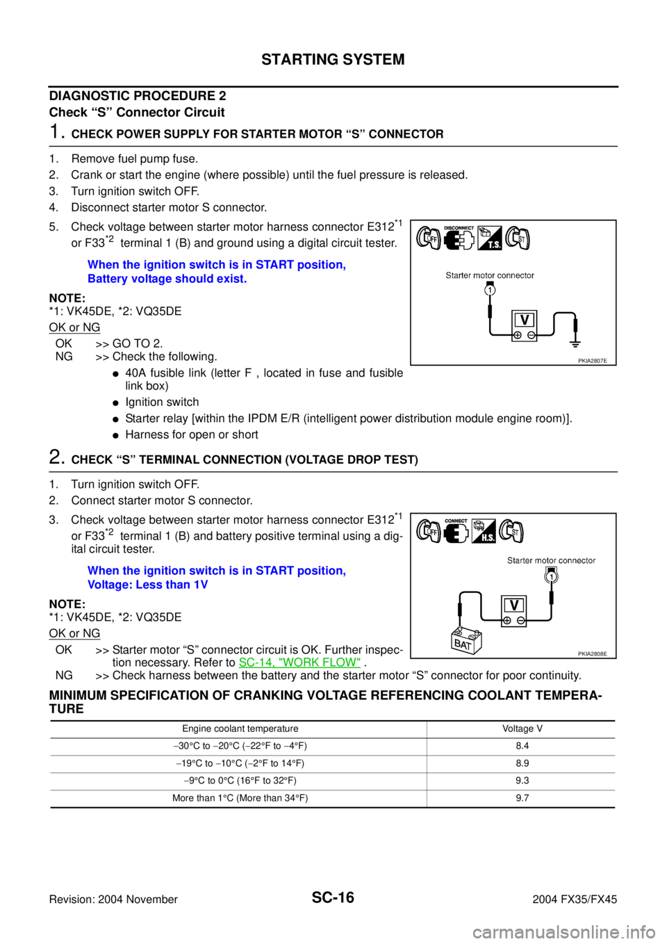
DIAGNOSTIC PROCEDURE 2
Check “S” Connector Circuit
1. CHECK POWER SUPPLY FOR STARTER MOTOR “S” CONNECTOR
1. Remove fuel pump fuse.
2. Crank or start the engine (where possible) until the fuel pressure is released.
3. Turn ignition switch OFF.
4. Disconnect starter motor S connector.
5. Check voltage between starter motor harness connector E312
*1
or F33*2 terminal 1 (B) and ground using a digital circuit tester.
NOTE:
*1: VK45DE, *2: VQ35DE
OK or NG
OK >> GO TO 2.
NG >> Check the following.
�40A fusible link (letter F , located in fuse and fusible
link box)
�Ignition switch
�Starter relay [within the IPDM E/R (intelligent power distribution module engine room)].
�Harness for open or short
2. CHECK “S” TERMINAL CONNECTION (VOLTAGE DROP TEST)
1. Turn ignition switch OFF.
2. Connect starter motor S connector.
3. Check voltage between starter motor harness connector E312
*1
or F33*2 terminal 1 (B) and battery positive terminal using a dig-
ital circuit tester.
NOTE:
*1: VK45DE, *2: VQ35DE
OK or NG
OK >> Starter motor “S” connector circuit is OK. Further inspec-
tion necessary. Refer to SC-14, "
WORK FLOW" .
NG >> Check harness between the battery and the starter motor “S” connector for poor continuity.
MINIMUM SPECIFICATION OF CRANKING VOLTAGE REFERENCING COOLANT TEMPERA-
TURE
When the ignition switch is in START position,
Battery voltage should exist.
PKIA2807E
When the ignition switch is in START position,
Voltage: Less than 1V
PKIA2808E
Engine coolant temperature Voltage V
−30°C to −20°C (−22°F to −4°F) 8.4
−19°C to −10°C (−2°F to 14°F) 8.9
−9°C to 0°C (16°F to 32°F) 9.3
More than 1°C (More than 34°F) 9.7
Page 4310 of 4449
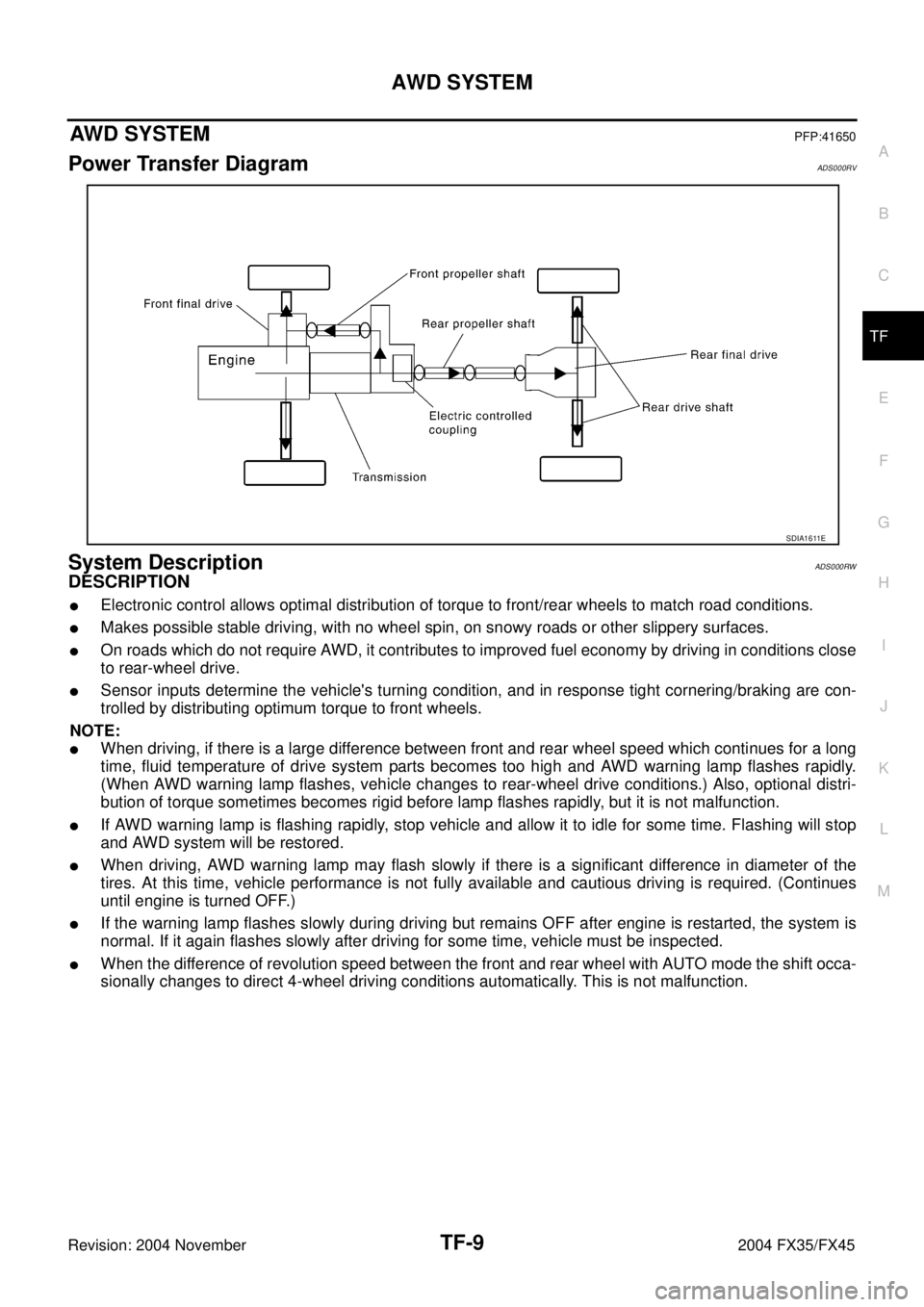
AWD SYSTEM
TF-9
C
E
F
G
H
I
J
K
L
MA
B
TF
Revision: 2004 November 2004 FX35/FX45
AWD SYSTEMPFP:41650
Power Transfer DiagramADS000RV
System DescriptionADS000RW
DESCRIPTION
�Electronic control allows optimal distribution of torque to front/rear wheels to match road conditions.
�Makes possible stable driving, with no wheel spin, on snowy roads or other slippery surfaces.
�On roads which do not require AWD, it contributes to improved fuel economy by driving in conditions close
to rear-wheel drive.
�Sensor inputs determine the vehicle's turning condition, and in response tight cornering/braking are con-
trolled by distributing optimum torque to front wheels.
NOTE:
�When driving, if there is a large difference between front and rear wheel speed which continues for a long
time, fluid temperature of drive system parts becomes too high and AWD warning lamp flashes rapidly.
(When AWD warning lamp flashes, vehicle changes to rear-wheel drive conditions.) Also, optional distri-
bution of torque sometimes becomes rigid before lamp flashes rapidly, but it is not malfunction.
�If AWD warning lamp is flashing rapidly, stop vehicle and allow it to idle for some time. Flashing will stop
and AWD system will be restored.
�When driving, AWD warning lamp may flash slowly if there is a significant difference in diameter of the
tires. At this time, vehicle performance is not fully available and cautious driving is required. (Continues
until engine is turned OFF.)
�If the warning lamp flashes slowly during driving but remains OFF after engine is restarted, the system is
normal. If it again flashes slowly after driving for some time, vehicle must be inspected.
�When the difference of revolution speed between the front and rear wheel with AUTO mode the shift occa-
sionally changes to direct 4-wheel driving conditions automatically. This is not malfunction.
SDIA1611E