Page 1031 of 4449
BL-224
IVIS (INFINITI VEHICLE IMMOBILIZER SYSTEM-NATS)
Revision: 2004 November 2004 FX35/FX45
4. PERFORM INITIALIZATION WITH CONSULT-II AGAIN
1. Replace BCM.
2. Perform initialization with CONSULT-II.
For initialization, refer to “CONSULT-II Operation Manual NATS-
IVIS/NVIS”.
NOTE:
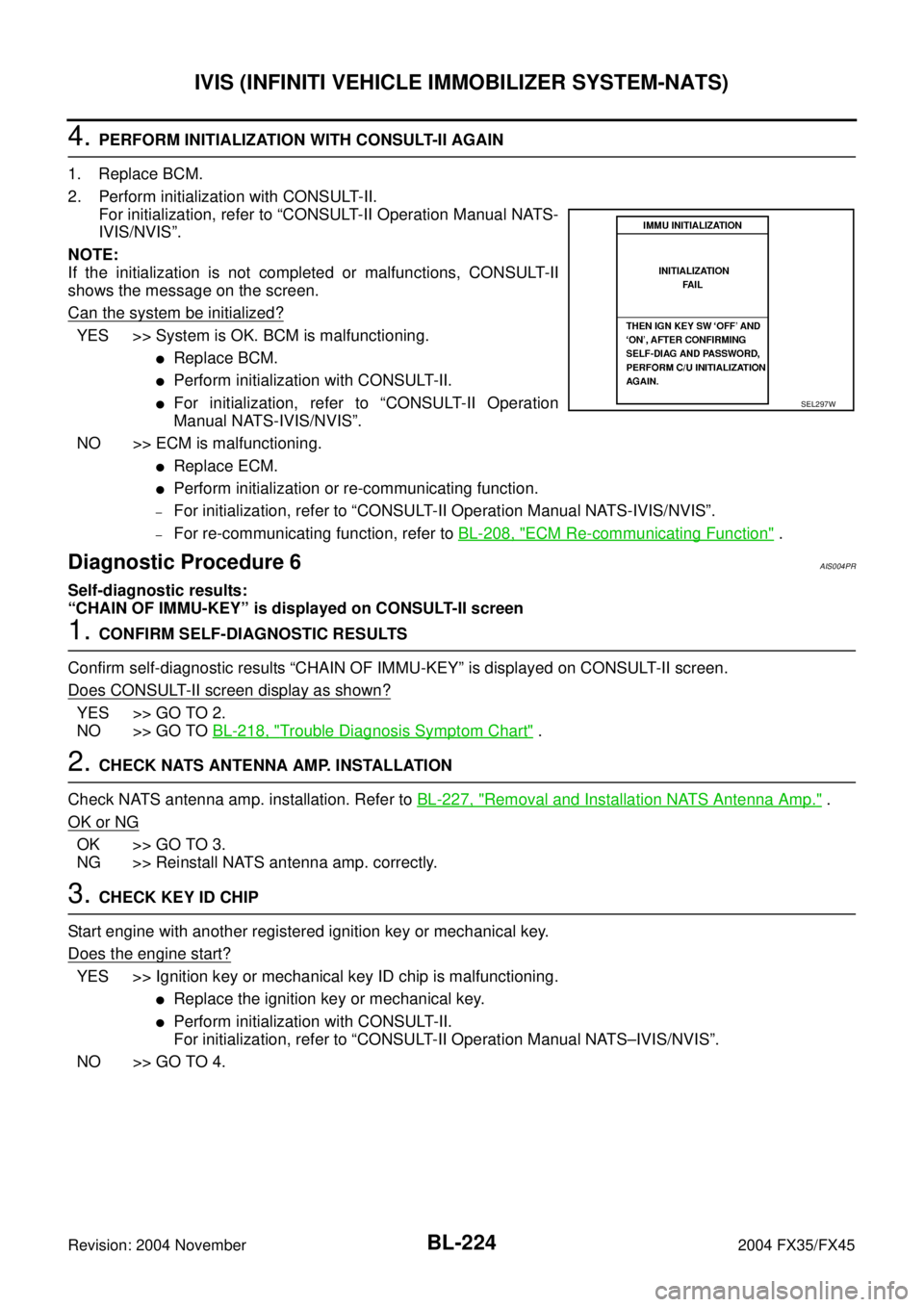
If the initialization is not completed or malfunctions, CONSULT-II
shows the message on the screen.
Can the system be initialized?
YES >> System is OK. BCM is malfunctioning.
�Replace BCM.
�Perform initialization with CONSULT-II.
�For initialization, refer to “CONSULT-II Operation
Manual NATS-IVIS/NVIS”.
NO >> ECM is malfunctioning.
�Replace ECM.
�Perform initialization or re-communicating function.
–For initialization, refer to “CONSULT-II Operation Manual NATS-IVIS/NVIS”.
–For re-communicating function, refer to BL-208, "ECM Re-communicating Function" .
Diagnostic Procedure 6AIS004PR
Self-diagnostic results:
“CHAIN OF IMMU-KEY” is displayed on CONSULT-II screen
1. CONFIRM SELF-DIAGNOSTIC RESULTS
Confirm self-diagnostic results “CHAIN OF IMMU-KEY” is displayed on CONSULT-II screen.
Does CONSULT-II screen display as shown?
YES >> GO TO 2.
NO >> GO TO BL-218, "
Trouble Diagnosis Symptom Chart" .
2. CHECK NATS ANTENNA AMP. INSTALLATION
Check NATS antenna amp. installation. Refer to BL-227, "
Removal and Installation NATS Antenna Amp." .
OK or NG
OK >> GO TO 3.
NG >> Reinstall NATS antenna amp. correctly.
3. CHECK KEY ID CHIP
Start engine with another registered ignition key or mechanical key.
Does the engine start?
YES >> Ignition key or mechanical key ID chip is malfunctioning.
�Replace the ignition key or mechanical key.
�Perform initialization with CONSULT-II.
For initialization, refer to “CONSULT-II Operation Manual NATS–IVIS/NVIS”.
NO >> GO TO 4.
SEL297W
Page 1033 of 4449
BL-226
IVIS (INFINITI VEHICLE IMMOBILIZER SYSTEM-NATS)
Revision: 2004 November 2004 FX35/FX45
7. CHECK NATS ANTENNA AMP. GROUND LINE CIRCUIT
1. Turn ignition switch “OFF”.
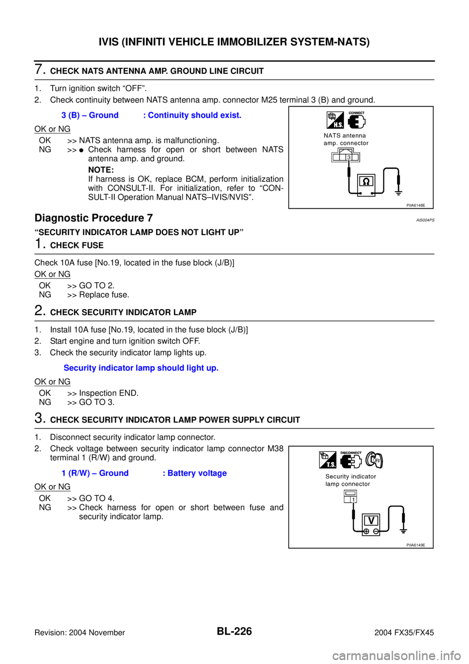
2. Check continuity between NATS antenna amp. connector M25 terminal 3 (B) and ground.
OK or NG
OK >> NATS antenna amp. is malfunctioning.
NG >>
�Check harness for open or short between NATS
antenna amp. and ground.
NOTE:
If harness is OK, replace BCM, perform initialization
with CONSULT-II. For initialization, refer to “CON-
SULT-II Operation Manual NATS–IVIS/NVIS”.
Diagnostic Procedure 7AIS004PS
“SECURITY INDICATOR LAMP DOES NOT LIGHT UP”
1. CHECK FUSE
Check 10A fuse [No.19, located in the fuse block (J/B)]
OK or NG
OK >> GO TO 2.
NG >> Replace fuse.
2. CHECK SECURITY INDICATOR LAMP
1. Install 10A fuse [No.19, located in the fuse block (J/B)]
2. Start engine and turn ignition switch OFF.
3. Check the security indicator lamp lights up.
OK or NG
OK >> Inspection END.
NG >> GO TO 3.
3. CHECK SECURITY INDICATOR LAMP POWER SUPPLY CIRCUIT
1. Disconnect security indicator lamp connector.
2. Check voltage between security indicator lamp connector M38
terminal 1 (R/W) and ground.
OK or NG
OK >> GO TO 4.
NG >> Check harness for open or short between fuse and
security indicator lamp. 3 (B) – Ground : Continuity should exist.
PIIA6148E
Security indicator lamp should light up.
1 (R/W) – Ground : Battery voltage
PIIA6149E
Page 1054 of 4449
BODY REPAIR
BL-247
C
D
E
F
G
H
J
K
L
MA
B
BL
Revision: 2004 November2004 FX35/FX45
ENGINE COMPARTMENT
Measurement
SIIA2260E
Page 1099 of 4449
BR-6
BRAKE PEDAL
Revision: 2004 November 2004 FX35/FX45
BRAKE PEDALPFP:46501
Inspection and AdjustmentAFS001MT
PLAY AND CLEARANCE BETWEEN BRAKE PEDAL AND FLOOR PANEL WITH PEDAL
DEPRESSED
1. Check brake pedal height from dash lower panel.
2. Adjust height referring to the following specifications.
SFIA1450E
HBrake pedal free height (from dash lower panel
top surface)161.5 − 171.5 mm (6.36 − 6.75 in)
DBrake pedal depressed height [under a force of
490 N (50 kg, 110 lb) with engine running]More than 80 mm (3.15 in)
CClearance between bracket and the threaded end
of stop lamp switch or ASCD cancel switch (or
brake switch)0.74 − 1.96 mm (0.0291−0.0772 in)
A Pedal play 3 − 11 mm (0.12 − 0.43 in)
Page 1100 of 4449
BRAKE PEDAL
BR-7
C
D
E
G
H
I
J
K
L
MA
B
BR
Revision: 2004 November 2004 FX35/FX45
ADJUSTMENT
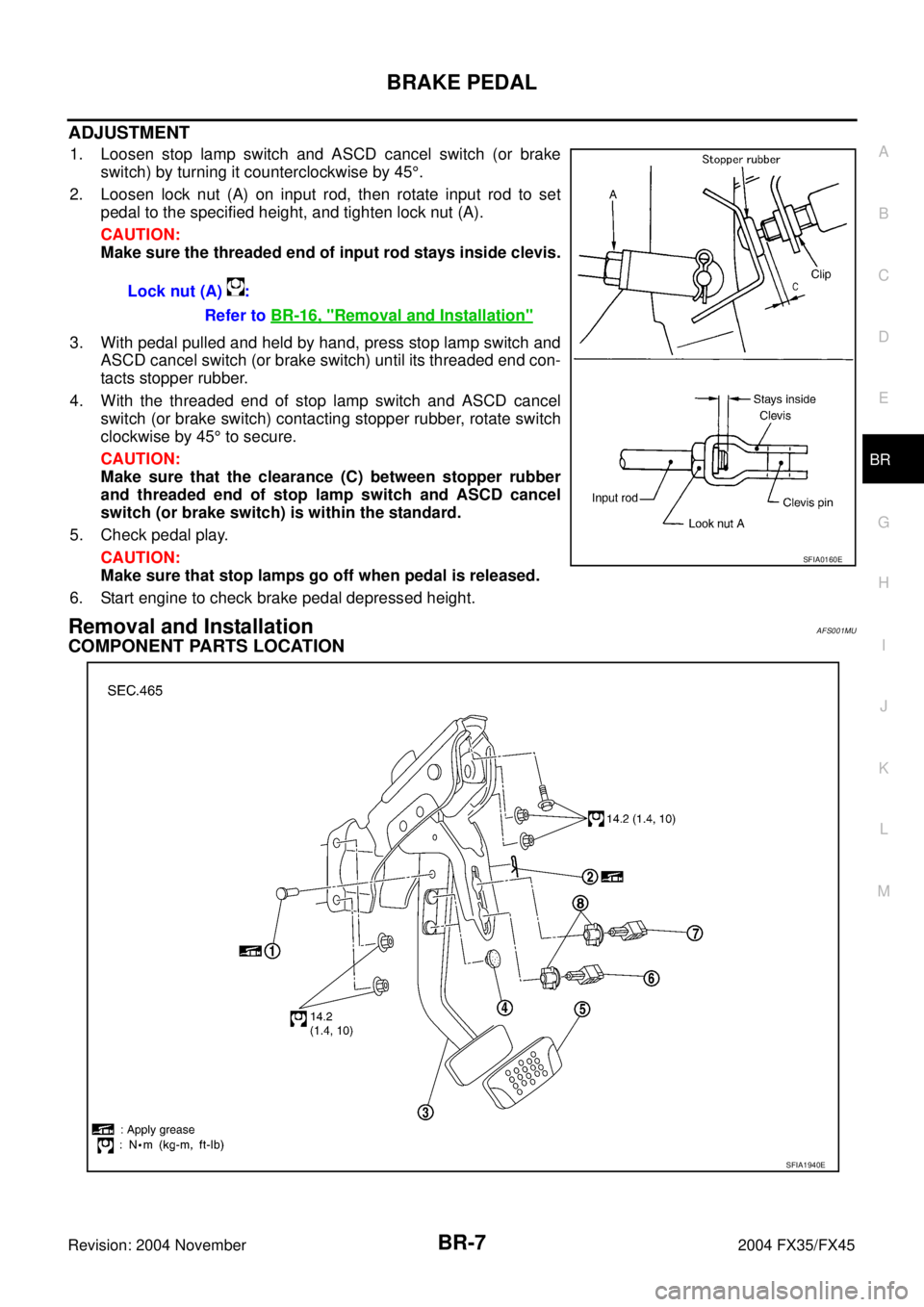
1. Loosen stop lamp switch and ASCD cancel switch (or brake
switch) by turning it counterclockwise by 45°.
2. Loosen lock nut (A) on input rod, then rotate input rod to set
pedal to the specified height, and tighten lock nut (A).
CAUTION:
Make sure the threaded end of input rod stays inside clevis.
3. With pedal pulled and held by hand, press stop lamp switch and
ASCD cancel switch (or brake switch) until its threaded end con-
tacts stopper rubber.
4. With the threaded end of stop lamp switch and ASCD cancel
switch (or brake switch) contacting stopper rubber, rotate switch
clockwise by 45° to secure.
CAUTION:
Make sure that the clearance (C) between stopper rubber
and threaded end of stop lamp switch and ASCD cancel
switch (or brake switch) is within the standard.
5. Check pedal play.
CAUTION:
Make sure that stop lamps go off when pedal is released.
6. Start engine to check brake pedal depressed height.
Removal and InstallationAFS001MU
COMPONENT PARTS LOCATION
Lock nut (A) :
Refer to BR-16, "
Removal and Installation"
SFIA0160E
SFIA1940E
Page 1105 of 4449
BR-12
BRAKE PIPING AND HOSE
Revision: 2004 November 2004 FX35/FX45
Removal and Installation of Rear Brake Piping and Brake Hose AFS001N0
REMOVAL
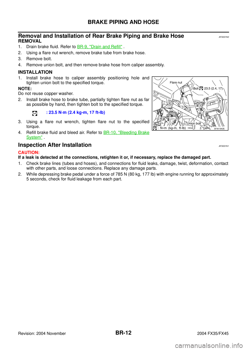
1. Drain brake fluid. Refer to BR-9, "Drain and Refill" .
2. Using a flare nut wrench, remove brake tube from brake hose.
3. Remove bolt.
4. Remove union bolt, and then remove brake hose from caliper assembly.
INSTALLATION
1. Install brake hose to caliper assembly positioning hole and
tighten union bolt to the specified torque.
NOTE:
Do not reuse copper washer.
2. Install brake hose to brake tube, partially tighten flare nut as far
as possible by hand, then tighten bolt to the specified torque.
3. Using a flare nut wrench, tighten flare nut to the specified
torque.
4. Refill brake fluid and bleed air. Refer to BR-10, "
Bleeding Brake
System" .
Inspection After InstallationAFS001N1
CAUTION:
If a leak is detected at the connections, retighten it or, if necessary, replace the damaged part.
1. Check brake lines (tubes and hoses), and connections for fluid leaks, damage, twist, deformation, contact
with other parts, and loose connections. Replace any damage parts.
2. While depressing brake pedal under a force of 785 N (80 kg, 177 lb) with engine running for approximately
5 seconds, check for fluid leakage from each part.: 23.5 N·m (2.4 kg-m, 17 ft-lb)
SFIA1942E
Page 1108 of 4449
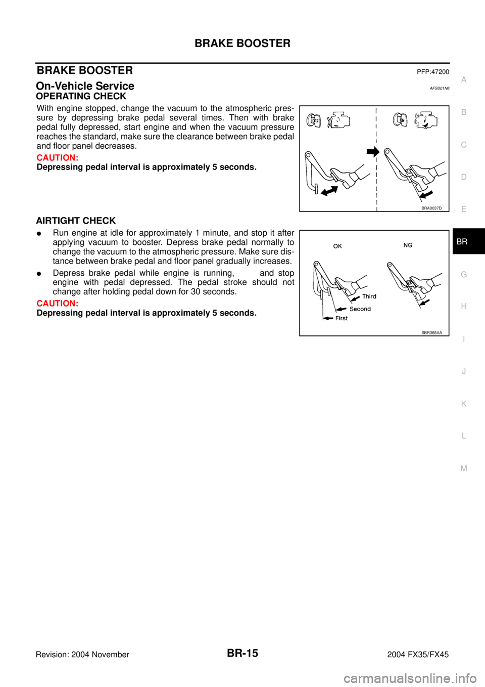
BRAKE BOOSTER
BR-15
C
D
E
G
H
I
J
K
L
MA
B
BR
Revision: 2004 November 2004 FX35/FX45
BRAKE BOOSTERPFP:47200
On-Vehicle ServiceAFS001N6
OPERATING CHECK
With engine stopped, change the vacuum to the atmospheric pres-
sure by depressing brake pedal several times. Then with brake
pedal fully depressed, start engine and when the vacuum pressure
reaches the standard, make sure the clearance between brake pedal
and floor panel decreases.
CAUTION:
Depressing pedal interval is approximately 5 seconds.
AIRTIGHT CHECK
�Run engine at idle for approximately 1 minute, and stop it after
applying vacuum to booster. Depress brake pedal normally to
change the vacuum to the atmospheric pressure. Make sure dis-
tance between brake pedal and floor panel gradually increases.
�Depress brake pedal while engine is running, and stop
engine with pedal depressed. The pedal stroke should not
change after holding pedal down for 30 seconds.
CAUTION:
Depressing pedal interval is approximately 5 seconds.
BRA0037D
SBR365AA
Page 1112 of 4449
VACUUM LINES
BR-19
C
D
E
G
H
I
J
K
L
MA
B
BR
Revision: 2004 November 2004 FX35/FX45
CHECK VALVE INSPECTION
Airtightness Inspection
Use a handy vacuum pump to check.
When connected to booster side (1):
Vacuum decrease should be within 1.3 kPa
(10 mmHg, 0.39 inHg) for 15 seconds under
a vacuum of – 66.7 kPa (– 500 mmHg, –
19.69 inHg)
When connected to engine side (2):
No vacuum will be applied
SFIA0210E