Page 2875 of 4449
EM-150
[VQ35DE]
SERVICE DATA AND SPECIFICATIONS (SDS)
Revision: 2004 November 2004 FX35/FX45
CYLINDER HEAD
Unit: mm (in)
Valve Dimensions
Unit: mm (in) Items Standard Limit
Head surface distortion 0.03 (0.0012) 0.1 (0.004)
Normal cylinder head height “H” 126.3 - 126.5 (4.972 - 4.980)
PBIC0924E
Valve head diameter “D” Intake 37.0 - 37.3 (1.4567 - 1.4685)
Exhaust 31.2 - 31.5 (1.228 - 1.240)
Valve length “L”Intake 96.37 (3.7941)
Exhaust 93.90 (3.6968)
Valve stem diameter “d”Intake 5.965 - 5.980 (0.2348 - 0.2354)
Exhaust 5.955 - 5.970 (0.2344 - 0.2350)
Valve seat angle “α”Intake
45°15′ - 45°45′
Exhaust
Valve margin “T”Intake 1.1 (0.043)
Exhaust 1.3 (0.051)
Valve margin “T” limitMore than 0.5 (0.020)
Valve stem end surface grinding limit Less than 0.2 (0.008)
SEM188
Page 2886 of 4449
![INFINITI FX35 2004 Service Manual PRECAUTIONS
EM-161
[VK45DE]
C
D
E
F
G
H
I
J
K
L
MA
EM
Revision: 2004 November 2004 FX35/FX45
3. Attach liquid gasket tube to tube presser [SST: WS39930000
(—)].
Use Genuine RTV Silicone Sealant or e](/manual-img/42/57021/w960_57021-2885.png "INFINITI FX35 2004 Service Manual PRECAUTIONS
EM-161
[VK45DE]
C
D
E
F
G
H
I
J
K
L
MA
EM
Revision: 2004 November 2004 FX35/FX45
3. Attach liquid gasket tube to tube presser [SST: WS39930000
(—)].
Use Genuine RTV Silicone Sealant or e")
PRECAUTIONS
EM-161
[VK45DE]
C
D
E
F
G
H
I
J
K
L
MA
EM
Revision: 2004 November 2004 FX35/FX45
3. Attach liquid gasket tube to tube presser [SST: WS39930000
(—)].
Use Genuine RTV Silicone Sealant or equivalent. Refer to
GI-48, "
RECOMMENDED CHEMICAL PRODUCTS AND
SEALANTS" .
4. Apply liquid gasket without breaks to the specified location with the specified dimensions.
�If there is a groove for the liquid gasket application, apply liquid gasket to the groove.
�As for the bolt holes, normally apply liquid gasket inside the
holes. Occasionally, it should be applied outside the holes.
Make sure to read the text of this manual.
�Within five minutes of liquid gasket application, install the mat-
ing component.
�If liquid gasket protrudes, wipe it off immediately.
�Do not retighten after the installation.
�Wait 30 minutes or more after installation before refilling
engine with engine oil and engine coolant.
CAUTION:
If there are specific instructions in this manual, observe
them.
EMA0622D
SEM159F
Page 2890 of 4449
![INFINITI FX35 2004 Service Manual PREPARATION
EM-165
[VK45DE]
C
D
E
F
G
H
I
J
K
L
MA
EM
Revision: 2004 November 2004 FX35/FX45
Valve seat cutter set Finishing valve seat dimensions
Piston ring expander Removing and installing piston r](/manual-img/42/57021/w960_57021-2889.png "INFINITI FX35 2004 Service Manual PREPARATION
EM-165
[VK45DE]
C
D
E
F
G
H
I
J
K
L
MA
EM
Revision: 2004 November 2004 FX35/FX45
Valve seat cutter set Finishing valve seat dimensions
Piston ring expander Removing and installing piston r")
PREPARATION
EM-165
[VK45DE]
C
D
E
F
G
H
I
J
K
L
MA
EM
Revision: 2004 November 2004 FX35/FX45
Valve seat cutter set Finishing valve seat dimensions
Piston ring expander Removing and installing piston ring
Valve guide drift Removing and installing valve guide
Intake and Exhaust:
a: 9.5 mm (0.374 in) dia.
b: 5.5 mm (0.217 in) dia.
Valve guide reamer (1): Reaming valve guide inner hole
(2): Reaming hole for oversize valve guide
Intake and Exhaust:
d
1 : 6.0 mm (0.236 in) dia.
d
2 : 10.2 mm (0.402 in) dia.
(J-43897-18)
(J-43897-12)
Oxygen sensor thread cleanerReconditioning the exhaust system threads
before installing a new heated oxygen
sensor (Use with anti-seize lubricant shown
below.)
a: J-43897-18 (18 mm dia.) for zirconia
heated oxygen sensor
b: J-43897-12 (12 mm dia.) for titania
heated oxygen sensor
Anti-seize lubricant (Permatex 133AR
or equivalent meeting MIL
specification MIL-A-907)Lubricating oxygen sensor thread cleaning
tool when reconditioning exhaust system
threads (Kent-Moore No.)
Tool nameDescription
S-NT048
S-NT030
S-NT015
S-NT016
AEM488
AEM489
Page 2955 of 4449
![INFINITI FX35 2004 Service Manual EM-230
[VK45DE]
CYLINDER HEAD
Revision: 2004 November 2004 FX35/FX45
7. Install valve collet.
�Compress valve spring with valve spring compressor, attach-
ment and adapter (SST). Install valve collet](/manual-img/42/57021/w960_57021-2954.png "INFINITI FX35 2004 Service Manual EM-230
[VK45DE]
CYLINDER HEAD
Revision: 2004 November 2004 FX35/FX45
7. Install valve collet.
�Compress valve spring with valve spring compressor, attach-
ment and adapter (SST). Install valve collet")
EM-230
[VK45DE]
CYLINDER HEAD
Revision: 2004 November 2004 FX35/FX45
7. Install valve collet.
�Compress valve spring with valve spring compressor, attach-
ment and adapter (SST). Install valve collet with magnetic
hand.
CAUTION:
When working, take care not to damage valve lifter holes.
�Tap stem edge lightly with plastic hammer after installation to
check its installed condition.
8. Install valve lifter and adjusting shim.
�Install in the original position.
9. Install spark plug tube.
�Press-fit spark plug tube following procedure below.
a. Remove old liquid gasket adhering to cylinder-head mounting
hole.
b. Apply liquid gasket to area within approximately 12 mm (0.47 in)
from edge of spark plug tube press-fit side.
Use Genuine RTV Silicone Sealant or equivalent . Refer to
GI-48, "
RECOMMENDED CHEMICAL PRODUCTS AND
SEALANTS" .
c. Using drift, press-fit spark plug tube so that its height “H” is as
specified in the figure.
CAUTION:
�When press-fitting, take care not to deform spark plug tube.
�After press-fitting, wipe off liquid gasket protruding onto cylinder-head upper face.
10. Install spark plug with spark plug wrench (commercial service tool).
Inspection After DisassemblyABS006IS
VALVE DIMENSIONS
�Check dimensions of each valve. For dimensions, refer to .
�If dimensions are out of the standard, replace valve.EM-270,
"Valve Dimensions" .
PBIC2360E
Standard press-fit height “H” :
: 38.4 - 39.4 mm (1.512 - 1.551 in)
KBIA1248E
SEM188A
Page 2957 of 4449
![INFINITI FX35 2004 Service Manual EM-232
[VK45DE]
CYLINDER HEAD
Revision: 2004 November 2004 FX35/FX45
3. Using valve guide reamer (commercial service tool), ream cylin-
der head valve guide hole.
4. Heat cylinder head to 110 to 130°](/manual-img/42/57021/w960_57021-2956.png "INFINITI FX35 2004 Service Manual EM-232
[VK45DE]
CYLINDER HEAD
Revision: 2004 November 2004 FX35/FX45
3. Using valve guide reamer (commercial service tool), ream cylin-
der head valve guide hole.
4. Heat cylinder head to 110 to 130°")
EM-232
[VK45DE]
CYLINDER HEAD
Revision: 2004 November 2004 FX35/FX45
3. Using valve guide reamer (commercial service tool), ream cylin-
der head valve guide hole.
4. Heat cylinder head to 110 to 130°C (230 to 266°F) by soaking in
heated oil.
5. Press valve guide from camshaft side to dimensions as in the
figure.
CAUTION:
Cylinder head contains heat. When working, wear protec-
tive equipment to avoid getting burned.
6. Using valve guide reamer (commercial service tool), apply
reamer finish to valve guide.
VALVE SEAT CONTACT
�After confirming that the dimensions of valve guides and valves
are within specifications, perform this procedure.
�Apply prussian blue (or white lead) onto contacting surface of
valve seat to check the condition of the valve contact on the sur-
face.
�Check if the contact area band is continuous all around the cir-
cumference.
�If not, grind to adjust valve fitting and check again. If the contact-
ing surface still has NG conditions even after the re-check,
replace valve seat.Valve guide hole diameter (for service parts):
Intake and exhaust
: 10.175 - 10.196 mm (0.4006 - 0.4014 in)
SEM932C
SEM008A
PBIC0078E
Standard:
Intake and exhaust
: 6.000 - 6.018 mm (0.2362 - 0.2369 in)
SEM932C
SBIA0322E
Page 2958 of 4449
![INFINITI FX35 2004 Service Manual CYLINDER HEAD
EM-233
[VK45DE]
C
D
E
F
G
H
I
J
K
L
MA
EM
Revision: 2004 November 2004 FX35/FX45
VALVE SEAT REPLACEMENT
When valve seat is removed, replace with oversized [0.5 mm (0.020 in)] valve seat.](/manual-img/42/57021/w960_57021-2957.png "INFINITI FX35 2004 Service Manual CYLINDER HEAD
EM-233
[VK45DE]
C
D
E
F
G
H
I
J
K
L
MA
EM
Revision: 2004 November 2004 FX35/FX45
VALVE SEAT REPLACEMENT
When valve seat is removed, replace with oversized [0.5 mm (0.020 in)] valve seat.")
CYLINDER HEAD
EM-233
[VK45DE]
C
D
E
F
G
H
I
J
K
L
MA
EM
Revision: 2004 November 2004 FX35/FX45
VALVE SEAT REPLACEMENT
When valve seat is removed, replace with oversized [0.5 mm (0.020 in)] valve seat.
1. Bore out old seat until it collapses. Boring should not continue beyond the bottom face of the seat recess
in cylinder head. Set the machine depth stop to ensure this.
CAUTION:
Prevent to scratch cylinder head by excessive boring.
2. Ream cylinder head recess diameter for service valve seat.
�Be sure to ream in circles concentric to valve guide center.
This will enable valve to fit correctly.
3. Heat cylinder head to 110 to 130°C (230 to 266°F) by soaking in
heated oil.
4. Provide valve seats cooled well with dry ice. Force fit valve seat into cylinder head.
CAUTION:
�Avoid directly touching cold valve seats.
�Cylinder head contains heat. When working, wear protective equipment to avoid getting burned.
5. Using valve seat cutter set (commercial service tool) or valve
seat grinder, finish seat to the specified dimensions.
CAUTION:
When using valve seat cutter, firmly grip cutter handle with
both hands. Then, press on the contacting surface all
around the circumference to cut in a single drive. Improper
pressure on with cutter or cutting many different times may
result in stage valve seat. Oversize [0.5 mm (0.020 in)]
Intake : 37.500 - 37.516 mm (1.4764 - 1.4770 in)
Exhaust : 32.700 - 32.716 mm (1.2874 - 1.2880 in)
SEM795A
SEM008A
SEM934C
Page 2959 of 4449
EM-234
[VK45DE]
CYLINDER HEAD
Revision: 2004 November 2004 FX35/FX45
Grind to obtain the dimensions indicated in the figure.
6. Using compound, grind to adjust valve fitting.
7. Check again for normal contact. Refer to EM-232, "
VALVE SEAT CONTACT" .
VALVE SPRING SQUARENESS
�Set try square along the side of valve spring and rotate spring.
Measure the maximum clearance between the top face of spring
and try square.
�If it exceeds the limit, replace valve spring.
PBIC2363E
Limit : 2.0 mm (0.079 in)
PBIC0080E
Page 2960 of 4449
CYLINDER HEAD
EM-235
[VK45DE]
C
D
E
F
G
H
I
J
K
L
MA
EM
Revision: 2004 November 2004 FX35/FX45
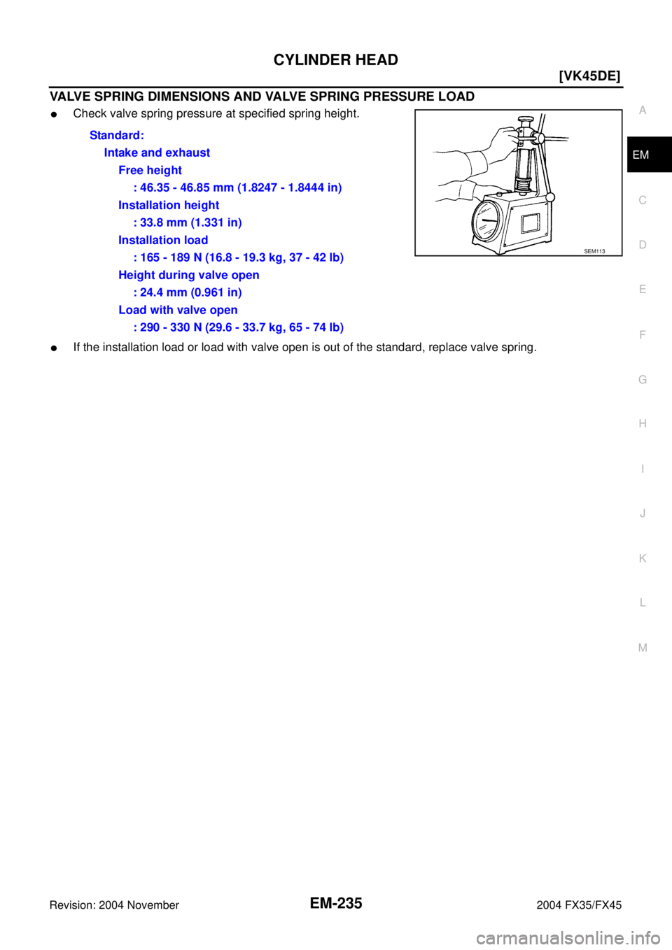
VALVE SPRING DIMENSIONS AND VALVE SPRING PRESSURE LOAD
�Check valve spring pressure at specified spring height.
�If the installation load or load with valve open is out of the standard, replace valve spring.Standard:
Intake and exhaust
Free height
: 46.35 - 46.85 mm (1.8247 - 1.8444 in)
Installation height
: 33.8 mm (1.331 in)
Installation load
: 165 - 189 N (16.8 - 19.3 kg, 37 - 42 lb)
Height during valve open
: 24.4 mm (0.961 in)
Load with valve open
: 290 - 330 N (29.6 - 33.7 kg, 65 - 74 lb)
SEM113
![INFINITI FX35 2004 Service Manual EM-150
[VQ35DE]
SERVICE DATA AND SPECIFICATIONS (SDS)
Revision: 2004 November 2004 FX35/FX45
CYLINDER HEAD
Unit: mm (in)
Valve Dimensions
Unit: mm (in) Items Standard Limit
Head surface distortion 0.0](/manual-img/42/57021/w960_57021-2874.png "INFINITI FX35 2004 Service Manual EM-150
[VQ35DE]
SERVICE DATA AND SPECIFICATIONS (SDS)
Revision: 2004 November 2004 FX35/FX45
CYLINDER HEAD
Unit: mm (in)
Valve Dimensions
Unit: mm (in) Items Standard Limit
Head surface distortion 0.0")
![INFINITI FX35 2004 Service Manual EM-234
[VK45DE]
CYLINDER HEAD
Revision: 2004 November 2004 FX35/FX45
Grind to obtain the dimensions indicated in the figure.
6. Using compound, grind to adjust valve fitting.
7. Check again for norma](/manual-img/42/57021/w960_57021-2958.png "INFINITI FX35 2004 Service Manual EM-234
[VK45DE]
CYLINDER HEAD
Revision: 2004 November 2004 FX35/FX45
Grind to obtain the dimensions indicated in the figure.
6. Using compound, grind to adjust valve fitting.
7. Check again for norma")