Page 3987 of 4449

RAX-6
WHEEL HUB
Revision: 2004 November 2004 FX35/FX45
10. Loosen fixing bolts and nuts of front lower link, radius rod, and rear lower link in side of suspension mem-
ber.
11. Set jack under rear lower link. Then remove fixing bolt in front lower link side of shock absorber with
power tool.
12. Remove bolt and nut in axle side of rear lower link with power tool. Then remove coil spring. Refer to
RSU-15, "
REAR LOWER LINK & COIL SPRING" .
13. Remove fixing bolts and nuts in axle side of front lower link, radius rod with power tool.
14. Remove suspension arm and cotter pin at axle, then loosen mounting nut.
15. Use a ball joint remover (suitable tool) to remove suspension arm from axle. Be careful not to damage ball
joint boot.
CAUTION:
Tighten temporarily mounting nut to prevent damage to threads and to prevent ball joint remover
(suitable tool) from coming off.
16. Remove axle from vehicle.
INSPECTION AFTER REMOVAL
Ball Joint Inspection
Check for boot breakage, axial looseness, and torque of suspension arm ball joint. Refer to RSU-11,
"INSPECTION AFTER REMOVAL" .
INSTALLATION
�Refer to RAX-5, "Removal and Installation" for tightening torque. Install in the reverse order of removal.
NOTE:
Refer to component parts location and do not reuse non-reusable parts.
�Perform final tightening of installation position of suspension links (rubber bushing) under unladen condi-
tions with tires on level ground, Check wheel alignment. Refer to RSU-5, "
Wheel Alignment Inspection" .
�After adjusting wheel alignment, adjust neutral position of steering angle sensor. Refer to BRC-6, "Adjust-
ment of Steering Angle Sensor Neutral Position" .
Disassembly and AssemblyADS000C6
DISASSEMBLY
Wheel Bearing
CAUTION:
Do not disassemble if wheel bearing has no trouble.
1. Remove wheel bearing fixing bolts and anchor block fixing nuts, and remove wheel hub and bearing
assembly, back plate and anchor block from axle.
2. Using a drift (SST) and a puller (suitable tool), press wheel hub
out to remove from wheel bearing.
SDIA1482E
Page 3989 of 4449
RAX-8
WHEEL HUB
Revision: 2004 November 2004 FX35/FX45
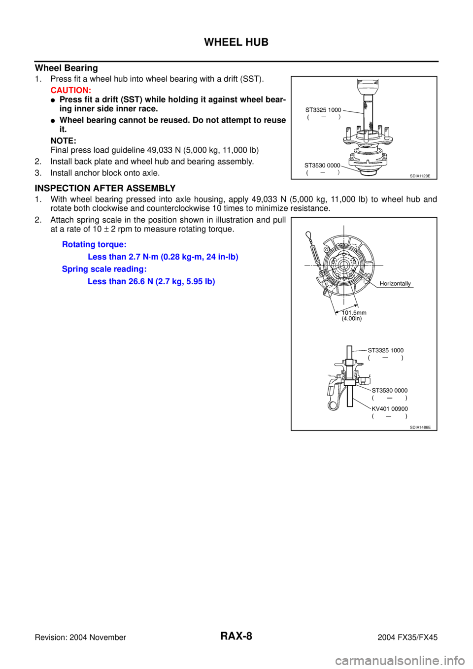
Wheel Bearing
1. Press fit a wheel hub into wheel bearing with a drift (SST).
CAUTION:
�Press fit a drift (SST) while holding it against wheel bear-
ing inner side inner race.
�Wheel bearing cannot be reused. Do not attempt to reuse
it.
NOTE:
Final press load guideline 49,033 N (5,000 kg, 11,000 lb)
2. Install back plate and wheel hub and bearing assembly.
3. Install anchor block onto axle.
INSPECTION AFTER ASSEMBLY
1. With wheel bearing pressed into axle housing, apply 49,033 N (5,000 kg, 11,000 lb) to wheel hub and
rotate both clockwise and counterclockwise 10 times to minimize resistance.
2. Attach spring scale in the position shown in illustration and pull
at a rate of 10 ± 2 rpm to measure rotating torque.
SDIA1120E
Rotating torque:
Less than 2.7 N·m (0.28 kg-m, 24 in-lb)
Spring scale reading:
Less than 26.6 N (2.7 kg, 5.95 lb)
SDIA1486E
Page 3990 of 4449

REAR DRIVE SHAFT
RAX-9
C
E
F
G
H
I
J
K
L
MA
B
RAX
Revision: 2004 November 2004 FX35/FX45
REAR DRIVE SHAFTPFP:39600
Removal and InstallationADS000C7
REMOVAL
1. Remove tire with power tool.
2. Remove cotter pin. Then remove lock nut from drive shaft.
3. Remove fixing nuts and bolts between side flange and drive shaft with power tool.
4. Separate drive shaft from wheel hub and bearing assembly by lightly tapping the end with a suitable ham-
mer and wood block. If it is hard to separate, use a suitable puller.
5. Remove drive shaft from axle.
CAUTION:
When removing drive shaft, do not apply an excessive angle to drive shaft joint. Also be careful
not to excessively extend slide joint.
INSPECTION AFTER REMOVAL
�Move joint up/down, left/right, and in the axial direction. Check
for any rough movement or significant looseness.
�Check boot for cracks or other damage, and also for grease
leakage.
�If a trouble is found, disassemble drive shaft, and then replace
with new one.
INSTALLATION
Refer to RAX-9, "Removal and Installation" for tightening torque. Install in the reverse order of removal.
NOTE:
Refer to component parts location and do not reuse non-reusable parts.
1. Side flange 2. Cotter pin
SDIA1487E
RAA0030D
Page 3996 of 4449
SERVICE DATA
RAX-15
C
E
F
G
H
I
J
K
L
MA
B
RAX
Revision: 2004 November 2004 FX35/FX45
SERVICE DATAPFP:00030
Wheel BearingADS000C9
Drive ShaftADS000KS
Axial end play0 mm (0 in)
Rotational torqueAt a load of 49,033 N (5,000 kg, 11,000 lb)
Less than 2.7 N·m (0.28 kg-m, 24 in-lb)
Measurement of spring scale Less than 26.6 N (2.7 kg, 5.95 lb)
Measuring point (Brake caliper installation points)
SDIA0801E
Joint Wheel side Final drive side
Engine model VQ35DE VK45DE VQ35DE VK45DE
Grease quantity86 − 96 g
(3.03 − 3.39 oz)140 − 160 g
(4.93 − 5.64 oz)124 − 134 g
(4.37 − 4.73 oz)175 − 195 g
(6.17 − 6.88 oz)
Boots installed length 97 mm (3.82 in) 141.5 mm (5.57 in) 93.9 mm (3.697 in) 147.9 mm (5.82 in)
Page 3999 of 4449
 “AIR BAG” and “SEAT
BELT PRE-TENSIONER”
AIS003AR
The Supplemen")
RF-2
PRECAUTIONS
Revision: 2004 November 2004 FX35/FX45
PRECAUTIONSPFP:00001
Precautions for Supplemental Restraint System (SRS) “AIR BAG” and “SEAT
BELT PRE-TENSIONER”
AIS003AR
The Supplemental Restraint System such as “AIR BAG” and “SEAT BELT PRE-TENSIONER”, used along
with a front seat belt, helps to reduce the risk or severity of injury to the driver and front passenger for certain
types of collision. This system includes seat belt switch inputs and dual stage front air bag modules. The SRS
system uses the seat belt switches to determine the front air bag deployment, and may only deploy one front
air bag, depending on the severity of a collision and whether the front occupants are belted or unbelted.
Information necessary to service the system safely is included in the SRS and SB section of this Service Man-
ual.
WARNING:
�To avoid rendering the SRS inoperative, which could increase the risk of personal injury or death
in the event of a collision which would result in air bag inflation, all maintenance must be per-
formed by an authorized NISSAN/INFINITI dealer.
�Improper maintenance, including incorrect removal and installation of the SRS, can lead to per-
sonal injury caused by unintentional activation of the system. For removal of Spiral Cable and Air
Bag Module, see the SRS section.
�Do not use electrical test equipment on any circuit related to the SRS unless instructed to in this
Service Manual. SRS wiring harnesses can be identified by yellow and/or orange harnesses or
harness connectors.
Precautions AIS003AS
�Disconnect both battery cables in advance.
�Do not tamper with or force air bag lid open, as this may adversely affect air bag performance.
�Be careful not to scratch pad and other parts.
�When removing or disassembling any part, be careful not to damage or deform it. Protect parts, which
may get in the way with cloth.
�When removing parts with a screwdriver or other tool, protect parts by wrapping them with vinyl or tape.
�Keep removed parts protected with cloth.
�If a clip is deformed or damaged, replace it.
�If an unreusable part is removed, replace it with a new one.
�Tighten bolts and nuts firmly to the specified torque.
�After re-assembly has been completed, make sure each part functions correctly.
�Remove stains in the following way.
Water-soluble stains:
Dip a soft cloth in warm water, and then squeeze it tightly. After wiping the stain, wipe with a soft dry cloth.
Oil stain:
Dissolve a synthetic detergent in warm water (density of 2 to 3% or less), dip the cloth, then clean off the stain
with the cloth. Next, dip the cloth in fresh water and squeeze it tightly. Then clean off the detergent completely.
Then wipe the area with a soft dry cloth.
�Do not use any organic solvent, such as thinner or benzine.
Page 4029 of 4449

RFD-2
PRECAUTIONS
Revision: 2004 November 2004 FX35/FX45
PRECAUTIONSPFP:00001
PrecautionsADS000K2
CAUTION:
�Before starting diagnosis of the vehicle, understand symptoms well. Perform correct and system-
atic operations.
�Check for the correct installation status prior removal or disassembly. When matching marks are
required, be sure they do not interfere with the function of the parts they are applied to.
�Carry out an overhaul in a clean work place, Using a dust proof room is recommended.
�Before disassembly, using steam or white gasoline, completely remove sand and mud from the
exterior the unit, preventing them from entering into the unit during disassembly or assembly.
�Check appearance of the disassembled parts for damage, deformation, and abnormal wear. If a
malfunction is detected, replace it with a new one.
�Normally replace lock pins, oil seals, and bearings with new ones every times they are removed.
�In principle, tighten bolts or nuts gradually in several steps working diagonally from inside to out-
side. If tightening sequence is specified, observe it.
�Clean and flush the parts sufficiently and blow them dry.
�Be careful not to damage the sliding surfaces and mating surface.
�When applying sealant, remove the old sealant from the mounting surface; then remove any mois-
ture, oil, and foreign materials from the application and mounting surfaces.
�Always use shop paper for cleaning the inside of components.
�Avoid using cotton gloves or a shop cloth to prevent entering of lint.
�During assembly, observe the specified tightening torque, and new differential gear oil, Vaseline,
or multi-purpose grease, as specified for each vehicle, when necessary.
Page 4032 of 4449
PREPARATION
RFD-5
C
E
F
G
H
I
J
K
L
MA
B
RFD
Revision: 2004 November 2004 FX35/FX45
Commercial Service ToolsADS000JN
ST3127S000 (J25765-A)
1. GG91030000
Torque wrench (J25765)
2. HT62940000 ( – )
Socket adapter (1/2″)
3. HT62900000 ( – )
Socket adapter (3/8″)
Preload gaugeMeasuring pinion bearing preload and total
preload
ST33290001 (J34286)
Side bearing outer race pullerRemoving oil seal
Differential shim selection (J34309) Adjusting bearing preload gear height Tool number (Kent-Moore No.)
Tool nameDescription
NT124
NT713
NT134
Tool name Description
Power toolLoosening bolts and nuts
PBIC0190E
Page 4047 of 4449

RFD-20
REAR FINAL DRIVE ASSEMBLY
Revision: 2004 November 2004 FX35/FX45
5. Adjust clearance between rear face of side gear and thrust
washer by selecting side gear thrust washer. Refer to RFD-31,
"AVAILABLE PINION HEIGHT ADJUSTING WASHERS" .
Use two feeler gauges to prevent leaning of side gear as show-
ing figure.
SIDE BEARING PRELOAD
A selection of carrier side bearing adjusting washers is required for successful completion of this procedure.
1. Make sure all parts are clean. Also, make sure the bearings are
well lubricated with gear oil.
2. Place the differential case, with side bearings and bearing races
installed, into gear carrier.
3. Insert left and right original side bearing adjusting washers in
place between side bearings and carrier.
4. Install the side bearing caps in their correct locations and torque
the bearing cap retaining bolts.
5. Turn the carrier several times to seat the bearings.Clearance between side gear thrust washer and dif-
ferential case
: 0.20 mm (0.0079 in) or less
SPD828
SPD527
SPD924
SDIA1795E

Rotational torqueAt a lo")

1. GG91030000
Torque wrench (J25765)
2. HT6")