Page 4390 of 4449
SERVICE DATA
WT-33
C
D
F
G
H
I
J
K
L
MA
B
WT
Revision: 2004 November 2004 FX35/FX45
SERVICE DATAPFP:00030
Road WheelAES000KB
TireAES000KC
Unit: kPa (kg/cm2 , psi)
Tightening TorqueAES000KD
Kind of wheel Aluminum Steel (for emergency
use)
Deflection limitLateral deflection Less than 0.3 mm
(0.012 in)Less than 1.0 mm
(0.039 in)
Vertical deflection Less than 0.3 mm
(0.012 in)Less than 1.2 mm
(0.047 in)
Allowable quantity of
residual unbalanceDynamic
(At rim flange)Less than 7.5 g (0.26 oz)
(per side)—
Static (At rim flange) Less than 20 g (0.70 oz) —
Tire sizeAir pressure
Front wheel Rear wheel
P265/60R18 109V 220 (2.2, 32) 220 (2.2, 32)
P265/50R20 106V 220 (2.2, 32) 220 (2.2, 32)
T175/90D18 110M 420 (4.2, 60) 420 (4.2, 60)
Wheel nut 108 N·m (11 kg-m, 80 ft-lb)
Page 4420 of 4449

FRONT WIPER AND WASHER SYSTEM
WW-29
C
D
E
F
G
H
I
J
L
MA
B
WW
Revision: 2004 November 2004 FX35/FX45
2. Prior to wiper arm installation, turn on wiper switch to operate
wiper motor and then turn it “OFF” (auto stop).
3. Push wiper arm onto pivot shaft, paying attention to blind spline.
4. Attach washer tube to washer tube joint.
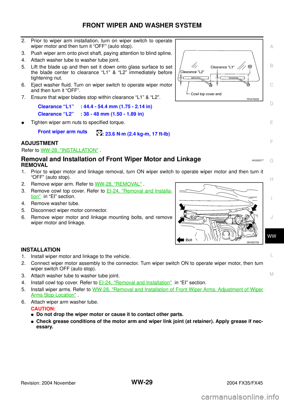
5. Lift the blade up and then set it down onto glass surface to set
the blade center to clearance “L1” & “L2” immediately before
tightening nut.
6. Eject washer fluid. Turn on wiper switch to operate wiper motor
and then turn it “OFF”.
7. Ensure that wiper blades stop within clearance “L1” & “L2”.
�Tighten wiper arm nuts to specified torque.
ADJUSTMENT
Refer to WW-28, "INSTALLATION" .
Removal and Installation of Front Wiper Motor and LinkageAKS00577
REMOVAL
1. Prior to wiper motor and linkage removal, turn ON wiper switch to operate wiper motor and then turn it
“OFF” (auto stop).
2. Remove wiper arm. Refer to WW-28, "
REMOVAL" .
3. Remove cowl top cover. Refer to EI-24, "
Removal and Installa-
tion" in “EI” section.
4. Remove washer tube.
5. Disconnect wiper motor connector.
6. Remove wiper motor and linkage mounting bolts, and remove
wiper motor and linkage.
INSTALLATION
1. Install wiper motor and linkage to the vehicle.
2. Connect wiper motor assembly to the connector. Turn wiper switch ON to operate wiper motor, then turn
wiper switch OFF (auto stop).
3. Attach washer tube to washer tube joint.
4. Install cowl top cover. Refer to EI-24, "
Removal and Installation" in “EI” section.
5. Install wiper arms. Refer to WW-28, "
Removal and Installation of Front Wiper Arms, Adjustment of Wiper
Arms Stop Location" .
6. Attach wiper arm washer tube.
CAUTION:
�Do not drop the wiper motor or cause it to contact other parts.
�Check grease conditions of the motor arm and wiper link joint (at retainer). Apply grease if nec-
essary.Clearance “L1” : 44.4 - 54.4 mm (1.75 - 2.14 in)
Clearance “L2” : 38 - 48 mm (1.50 - 1.89 in)
Front wiper arm nuts
: 23.6 N·m (2.4 kg-m, 17 ft-lb)
PKIA7843E
SKIA5070E
Page 4439 of 4449

WW-48
REAR WIPER AND WASHER SYSTEM
Revision: 2004 November 2004 FX35/FX45
Removal and Installation of Rear Wiper Arm, Adjustment of Wiper Arms Stop
Location
AKS0057T
REMOVAL
1. Operate wiper motor, and stop it at the auto stop position.
2. Remove cover wiper arm.
3. Remove wiper arm nut, and remove wiper arm from vehicle.
INSTALLATION
1. Prior to wiper arm installation, turn on wiper switch to operate
wiper motor and then turn it “OFF” (auto stop).
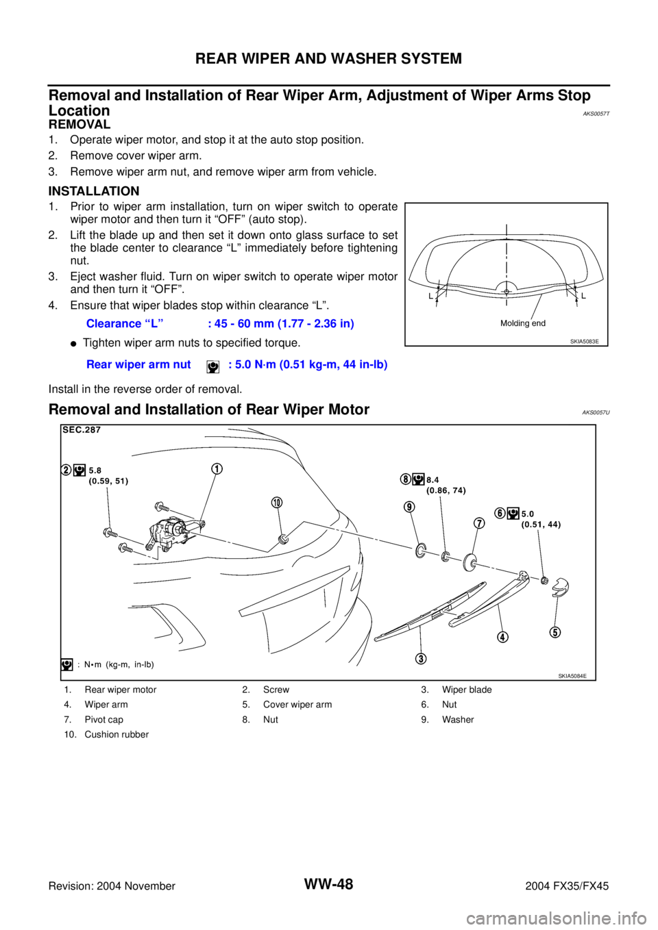
2. Lift the blade up and then set it down onto glass surface to set
the blade center to clearance “L” immediately before tightening
nut.
3. Eject washer fluid. Turn on wiper switch to operate wiper motor
and then turn it “OFF”.
4. Ensure that wiper blades stop within clearance “L”.
�Tighten wiper arm nuts to specified torque.
Install in the reverse order of removal.
Removal and Installation of Rear Wiper Motor AKS0057U
Clearance “L” : 45 - 60 mm (1.77 - 2.36 in)
Rear wiper arm nut : 5.0 N·m (0.51 kg-m, 44 in-lb)
SKIA5083E
1. Rear wiper motor 2. Screw 3. Wiper blade
4. Wiper arm 5. Cover wiper arm 6. Nut
7. Pivot cap 8. Nut 9. Washer
10. Cushion rubber
SKIA5084E
Page 4448 of 4449
HORN
WW-57
C
D
E
F
G
H
I
J
L
MA
B
WW
Revision: 2004 November 2004 FX35/FX45
Removal and InstallationAKS00584
REMOVAL
1. Remove front grille. Refer to EI-23, "Removal and Installation"
in “EI” section.
2. Disconnect all horn connectors.
3. Remove horn mounting bolt and remove horn from vehicle.
INSTALLATION
Tighten horn bolt to specified torque.
SKIA5093E
Horn mounting bolt
: 5.8 N·m (0.59 kg-m, 51 in-lb)