Page 964 of 4449
REAR DOOR LOCK
BL-157
C
D
E
F
G
H
J
K
L
MA
B
BL
Revision: 2004 November 2004 FX35/FX45
CAUTION:
Do not forcibly remove the TORX bolt (T30).
5. While pulling the outside handle, remove outside handle
escutcheon.
6. While pulling outside handle, slide toward rear of vehicle to
remove outside handle.
7. Remove the front gasket and rear gasket.
PIIA3553E
PIIA6344E
PIIA3555E
PIIA3557E
Page 965 of 4449
BL-158
REAR DOOR LOCK
Revision: 2004 November 2004 FX35/FX45
8. Remove the TORX bolt (T30), and remove the outside handle
bracket.
9. While pulling outside handle, slide toward front of vehicle to
remove outside handle bracket.
10. Reach to separate outside handle cable connection.
11. Remove the TORX bolts (T30) of door lock assembly.
12. Disconnect the door lock actuator connector and remove door lock assembly.
INSTALLATION
Install in the reverse order of removal.
CAUTION:
To install each rod, be sure to rotate the rod holder until a click is felt.
PIIA7117E
PIIA3558E
PIIA5059E
PIIA1090E
Page 966 of 4449
BACK DOOR
BL-159
C
D
E
F
G
H
J
K
L
MA
B
BL
Revision: 2004 November 2004 FX35/FX45
BACK DOORPFP:90100
Fitting AdjustmentAIS004O4
VERTICAL/LATERAL CLEARANCE ADJUSTMENT
1. With the striker released, loosen the bumper rubber lock nuts.
2. Close the back door lightly and adjust the surface height by rotating the bumper rubber and, then open the
back door to finally tighten the back door lock mounting bolts and bumper rubber lock nuts to the specified
torque.
Back Door AssemblyAIS004O5
REMOVAL
1. Remove roof rear garnish assembly. Refer to EI-44, "Removal and Installation" .
2. Disconnect the back door harness connector and AV antenna
feeder.
3. Washer hose is separated in the connection part.
4. Support the back door lock with a proper material to prevent it
from falling.
WARNING:
Body injury may occur if no supporting rod is holding the
back door open when removing the damper stay.
1. Bumper rubber 2. Back door striker 3. Screw
PIIB0208E
PIIA6028E
PIIA6061E
Page 968 of 4449
BACK DOOR
BL-161
C
D
E
F
G
H
J
K
L
MA
B
BL
Revision: 2004 November 2004 FX35/FX45
CAUTION:
After installing, perform fitting adjustment. Refer to BL-159, "
Fitting Adjustment" .
Removal and Installation of Back Door StayAIS004O7
REMOVAL
1. Support the back door lock with a proper material to prevent it
from falling.
WARNING:
Body injury may occur if no supporting rod is holding the
back door open when removing the damper stay.
2. Remove back door stay on back door.
3. Remove back door stay assembly on vehicle.
INSTALLATION
Install in the reverse order of removal.
CAUTION:
After installing, check operation.
Removal and Installation of Dave Tail Male & FemaleAIS004O8
REMOVAL
1. Remove the dave tail male.
PIIA6061E
PIIA6029E
PIIA6031E
PIIA6078E
Page 970 of 4449

BACK DOOR LOCK ASSEMBLY
BL-163
C
D
E
F
G
H
J
K
L
MA
B
BL
Revision: 2004 November 2004 FX35/FX45
BACK DOOR LOCK ASSEMBLYPFP:90504
Removal and Installation of Back Door Lock & Closure AssemblyAIS004OA
REMOVAL
1. Remove back door finisher. Refer to EI-46, "Removal and Installation" .
2. Disconnect the connector and the clip of the back door lock & closure assembly.
3. Remove the mounting bolts.
4. Disconnect the connector of the back door opener actuator.
5. Remove the mounting bolts, remove back door lock & closure assembly.
INSTALLATION
Install in the reverse order of removal.
CAUTION:
�After installing, check operation.
�After installing, perform fitting adjustment. Refer toBL-159, "Fitting Adjustment" .
INSPECTION
1. Check back door lock for the following.
�Malfunction noise or door closing and opening effort
�Component wear or damage
2. Apply body grease to the rotating part of the back door lock.
Removal and Installation of Back Door Opener SwitchAIS0061W
REMOVAL
1. Remove back door finisher. Refer to EI-46, "Removal and Installation" .
2. Remove back door outside finisher. Refer to EI-46, "
BACK DOOR TRIM" .
3. Remove licence lamp. Refer to LT- 1 4 5 , "
License Plate Lamp" .
4. Cut back door inner panel along with cutting groove line.
1. Bolt 2. Back door lock & closure assembly
PIIA6043E
PIIB1644E
Page 971 of 4449
BL-164
BACK DOOR LOCK ASSEMBLY
Revision: 2004 November 2004 FX35/FX45
CAUTION:
When cutting the back door panel, always wear safety
glasses, heavy gloves and a dust proof mask to prevent eye
and skin irritation from glass fiver splinters.
5. Disconnect back door opener switch harness connector (and rear view camera if equipped).
6. Remove opener switch from back door through hole.
INSTALLATION
Install in the reverse order of removal.
CAUTION:
After installing, check operation.
Disassembly and AssemblyAIS004OC
BACK DOOR LOCK & CLOSURE ASSEMBLY
CAUTION:
Be sure to remove or install the back door opener actuator motor with the back door lock & closure
assembly.
1. Remove the back door closure motor.
PIIB1645E
PIIB1647E
PIIA6080E
Page 972 of 4449

BACK DOOR AUTO CLOSURE SYSTEM
BL-165
C
D
E
F
G
H
J
K
L
MA
B
BL
Revision: 2004 November 2004 FX35/FX45
BACK DOOR AUTO CLOSURE SYSTEMPFP:90542
Component Parts and Harness Connector LocationAIS004OD
System DescriptionAIS004OE
When back door lock latch engaged with striker, striker is lowered by means of a motor the back door fully
closed.
CLOSE OPERATION
�Half-latch is turned off when back door enters the state of a half door and back door closure control unit
recognizes it.
�Back door closure control unit by which the signal is recognized operates closure motor in the close direc-
tion, and open switch is turned on.
�Close switch is turned on when back door becomes a full latch position by operating closure motor and
back door closure control unit operates closure motor in an open direction.
�The operation of closure motor is stopped, and back door enters all close states when back door moves in
an open direction, and open switch is turned off.
NON-OPERATION CONDITION
�When you close back door while pushing back door opener switch.
�When closing at once (within about 0.5 seconds) after back door is opened.
�When you do not close back door after back door opener switch is pushed.
PIIA6406E
Page 973 of 4449
BL-166
BACK DOOR AUTO CLOSURE SYSTEM
Revision: 2004 November 2004 FX35/FX45
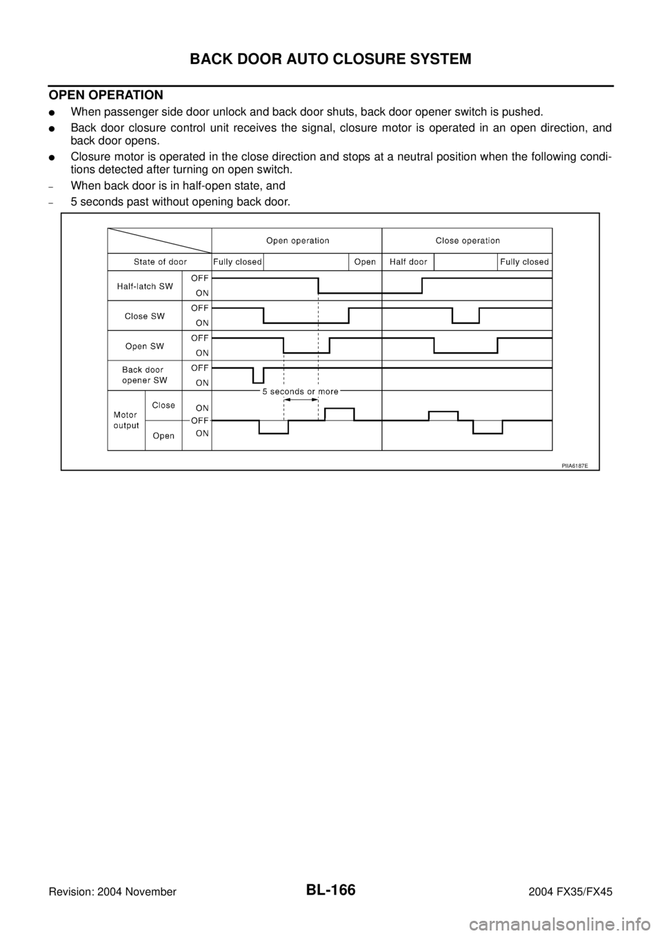
OPEN OPERATION
�When passenger side door unlock and back door shuts, back door opener switch is pushed.
�Back door closure control unit receives the signal, closure motor is operated in an open direction, and
back door opens.
�Closure motor is operated in the close direction and stops at a neutral position when the following condi-
tions detected after turning on open switch.
–When back door is in half-open state, and
–5 seconds past without opening back door.
PIIA6187E
.
5. While pulling the outside handle, remove outside handle
e")
, and remove the outside handle
bracket.
9. While pulling outside handle, slide toward front of vehicle to
rem")