Page 823 of 4449
BL-16
HOOD
Revision: 2004 November 2004 FX35/FX45
REMOVAL
1. Support the hood striker with a proper material to prevent it from
falling.
WARNING:
Body injury may occur if no supporting rod is holding the
hood open when removing the hood stay.
2. Remove the hood stays from the stud balls on the body side.
3. Remove the hinge mounting nuts on the hood to remove the hood assembly.
CAUTION:
Operate with two workers, because of its heavy weight.
INSTALLATION
Install in the reverse order of removal.
Removal and Installation of Hood Lock ControlAIS0051G
REMOVAL
1. Remove the front grill. Refer to EI-23, "Removal and Installation" .
2. Remove the front fender protector (LH). Refer to EI-25, "
Removal and Installation" .
3. Disconnect the hood lock cable from the hood lock, and clip it from the radiator core support upper and
hood ledge.
PIIA6058E
1. Hood lock 2. Hood lock cable 3. Clip
4. Hood ledge upper front LH 5. Dash lower cross member reinforce LH
PIIA6017E
Page 824 of 4449

HOOD
BL-17
C
D
E
F
G
H
J
K
L
MA
B
BL
Revision: 2004 November 2004 FX35/FX45
4. Remove instrument driver lower panel. Refer to IP-11, "Removal and Installation" .
5. After the bolt of the case with the air cleaner is disconnected, and it is moved, the cable is pulled.
6. Remove the grommet on the dashboard, and pull the hood lock cable toward the passenger room.
CAUTION:
While pulling, be careful not to damage (peeling) the outside of the hood lock cable.
INSTALLATION
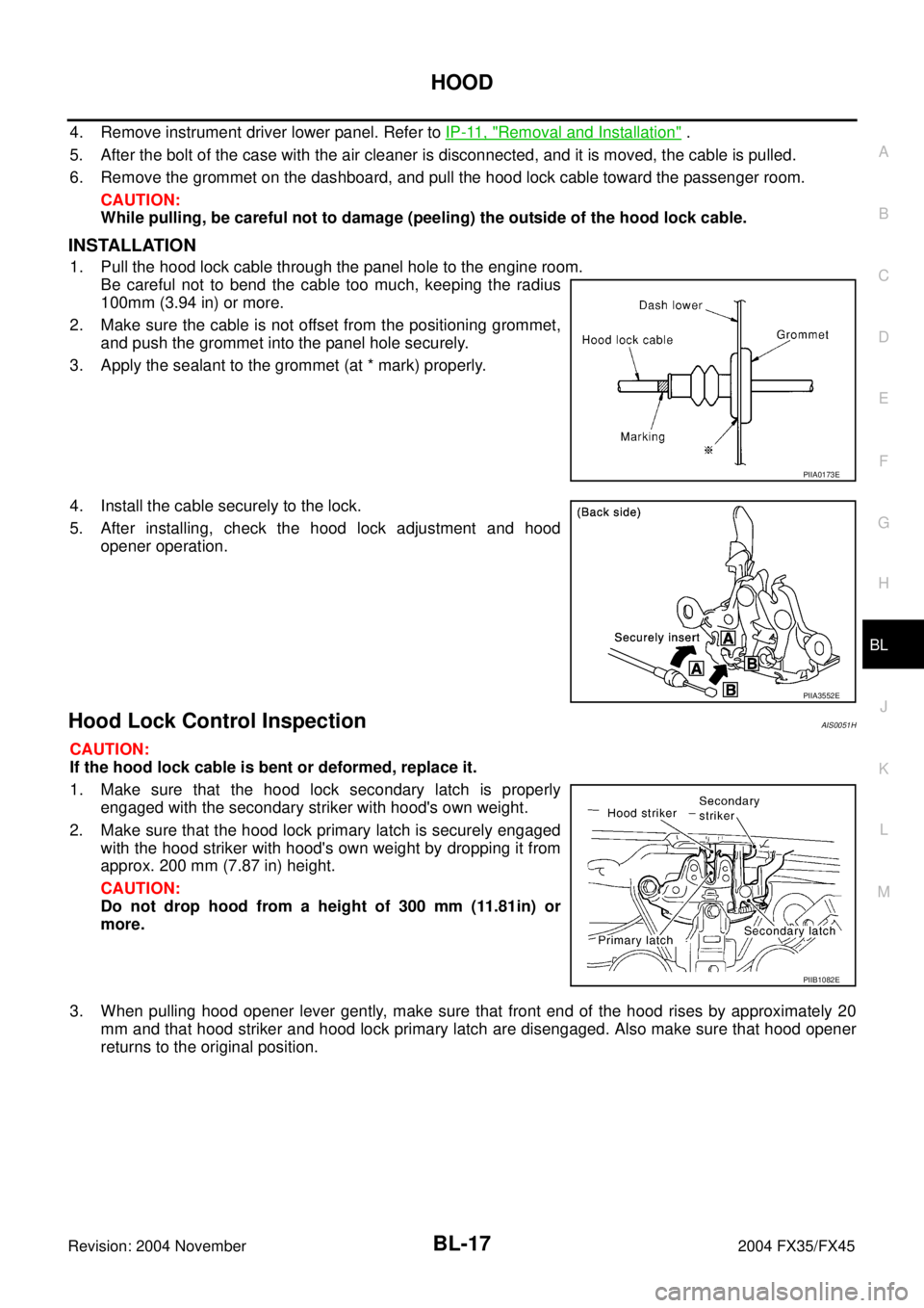
1. Pull the hood lock cable through the panel hole to the engine room.
Be careful not to bend the cable too much, keeping the radius
100mm (3.94 in) or more.
2. Make sure the cable is not offset from the positioning grommet,
and push the grommet into the panel hole securely.
3. Apply the sealant to the grommet (at * mark) properly.
4. Install the cable securely to the lock.
5. After installing, check the hood lock adjustment and hood
opener operation.
Hood Lock Control InspectionAIS0051H
CAUTION:
If the hood lock cable is bent or deformed, replace it.
1. Make sure that the hood lock secondary latch is properly
engaged with the secondary striker with hood's own weight.
2. Make sure that the hood lock primary latch is securely engaged
with the hood striker with hood's own weight by dropping it from
approx. 200 mm (7.87 in) height.
CAUTION:
Do not drop hood from a height of 300 mm (11.81in) or
more.
3. When pulling hood opener lever gently, make sure that front end of the hood rises by approximately 20
mm and that hood striker and hood lock primary latch are disengaged. Also make sure that hood opener
returns to the original position.
PIIA0173E
PIIA3552E
PIIB1082E
Page 956 of 4449

DOOR
BL-149
C
D
E
F
G
H
J
K
L
MA
B
BL
Revision: 2004 November 2004 FX35/FX45
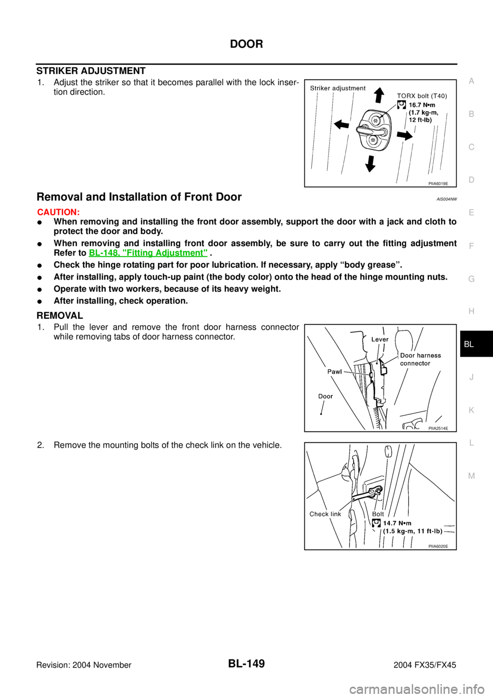
STRIKER ADJUSTMENT
1. Adjust the striker so that it becomes parallel with the lock inser-
tion direction.
Removal and Installation of Front DoorAIS004NW
CAUTION:
�When removing and installing the front door assembly, support the door with a jack and cloth to
protect the door and body.
�When removing and installing front door assembly, be sure to carry out the fitting adjustment
Refer to BL-148, "
Fitting Adjustment" .
�Check the hinge rotating part for poor lubrication. If necessary, apply “body grease”.
�After installing, apply touch-up paint (the body color) onto the head of the hinge mounting nuts.
�Operate with two workers, because of its heavy weight.
�After installing, check operation.
REMOVAL
1. Pull the lever and remove the front door harness connector
while removing tabs of door harness connector.
2. Remove the mounting bolts of the check link on the vehicle.
PIIA6019E
PIIA2514E
PIIA6020E
Page 957 of 4449
BL-150
DOOR
Revision: 2004 November 2004 FX35/FX45
3. Remove the door-side hinge mounting nuts, and remove the
door assembly.
INSTALLATION
Install in the reverse order of removal.
Removal and Installation of Rear DoorAIS004NX
CAUTION:
�When removing and installing the rear door assembly, support the door with a jack and cloth to
protect the door and body.
�When removing and installing rear door assembly, be sure to carry out the fitting adjustment Refer
to BL-148, "
Fitting Adjustment" .
�Check the hinge rotating part for poor lubrication. If necessary, apply “body grease”.
�After installing, apply touch-up paint (the body color) onto the head of the hinge mounting nuts.
�Operate with two workers, because of its heavy weight.
�After installing, check operation.
REMOVAL
1. Grommet is pulled out, and the Rear door harness connector is
detached.
2. Remove the mounting bolts of the check link on the vehicle.
PIIA6021E
PIIA2787E
PIIA6022E
Page 1065 of 4449
BL-258
BODY REPAIR
Revision: 2004 November2004 FX35/FX45
Precautions In Repairing High Strength SteelAIS00629
High strength steel is used for body panels in order to reduce vehicle weight.
Accordingly, precautions in repairing automotive bodies made of high strength steel are described below:
HIGH STRENGTH STEEL (HSS) USED IN NISSAN VEHICLES
SP130 is the most commonly used HSS.
SP150 HSS is used only on parts that require much more strength.Tensile strength Nissan/ Infiniti designation Major applicable parts
373 N/mm
2
(38kg/mm2,54klb/sq in)SP130
lFront & rear side member assembly
lHoodledge assembly
lLower dash
lHood
lOther reinforcements
Page 1430 of 4449
![INFINITI FX35 2004 Service Manual TROUBLE DIAGNOSIS
EC-89
[VQ35DE]
C
D
E
F
G
H
I
J
K
L
MA
EC
Revision: 2004 November 2004 FX35/FX45
1 - 6: The numbers refer to the order of inspection.
(continued on next page)
SYSTEM — ENGINE MECHAN INFINITI FX35 2004 Service Manual TROUBLE DIAGNOSIS
EC-89
[VQ35DE]
C
D
E
F
G
H
I
J
K
L
MA
EC
Revision: 2004 November 2004 FX35/FX45
1 - 6: The numbers refer to the order of inspection.
(continued on next page)
SYSTEM — ENGINE MECHAN](/manual-img/42/57021/w960_57021-1429.png)
TROUBLE DIAGNOSIS
EC-89
[VQ35DE]
C
D
E
F
G
H
I
J
K
L
MA
EC
Revision: 2004 November 2004 FX35/FX45
1 - 6: The numbers refer to the order of inspection.
(continued on next page)
SYSTEM — ENGINE MECHANICAL & OTHER
ECM 22333333333EC-401,
EC-404
Intake valve timing control solenoid valve cir-
cuit32 13223 3EC-408
PNP switch circuit 3 3 3 3 3EC-545
Refrigerant pressure sensor circuit 2 3 3 4EC-609
Electrical load signal circuit 3EC-614
Air conditioner circuit223333333 3 2AT C - 4 0
ABS actuator and electric unit (control unit) 4BRC-12
SYMPTOM
Reference
page
HARD/NO START/RESTART (EXCP. HA)
ENGINE STALL
HESITATION/SURGING/FLAT SPOT
SPARK KNOCK/DETONATION
LACK OF POWER/POOR ACCELERATION
HIGH IDLE/LOW IDLE
ROUGH IDLE/HUNTING
IDLING VIBRATION
SLOW/NO RETURN TO IDLE
OVERHEATS/WATER TEMPERATURE HIGH
EXCESSIVE FUEL CONSUMPTION
EXCESSIVE OIL CONSUMPTION
BATTERY DEAD (UNDER CHARGE)
Warranty symptom code AA AB AC AD AE AF AG AH AJ AK AL AM HA
Fuel Fuel tank
5
5FL-10
Fuel piping 5 5 5 5 5 5EM-45
Vapor lock—
Valve deposit
5 555 55 5—
Poor fuel (Heavy weight gaso-
line, Low octane)—
Page 1673 of 4449
![INFINITI FX35 2004 Service Manual EC-332
[VQ35DE]
DTC P0442 EVAP CONTROL SYSTEM
Revision: 2004 November 2004 FX35/FX45
9. CHECK IF EVAP CANISTER SATURATED WITH WATER
1. Remove EVAP canister with EVAP canister vent control valve and EV INFINITI FX35 2004 Service Manual EC-332
[VQ35DE]
DTC P0442 EVAP CONTROL SYSTEM
Revision: 2004 November 2004 FX35/FX45
9. CHECK IF EVAP CANISTER SATURATED WITH WATER
1. Remove EVAP canister with EVAP canister vent control valve and EV](/manual-img/42/57021/w960_57021-1672.png)
EC-332
[VQ35DE]
DTC P0442 EVAP CONTROL SYSTEM
Revision: 2004 November 2004 FX35/FX45
9. CHECK IF EVAP CANISTER SATURATED WITH WATER
1. Remove EVAP canister with EVAP canister vent control valve and EVAP control system pressure sensor
attached.
2. Does water drain from the EVAP canister?
Ye s o r N o
Yes >> GO TO 10.
No (With CONSULT-II)>>GO TO 12.
No (Without CONSULT-II)>>GO TO 13.
10. CHECK EVAP CANISTER
Weigh the EVAP canister with the EVAP canister vent control valve and EVAP control system pressure sensor
attached.
The weight should be less than 2.1 kg (4.6 lb).
OK or NG
OK (With CONSULT-II)>>GO TO 12.
OK (Without CONSULT-II)>>GO TO 13.
NG >> GO TO 11.
11 . DETECT MALFUNCTIONING PART
Check the following.
�EVAP canister for damage
�EVAP hose between EVAP canister and vehicle frame for clogging or poor connection
>> Repair hose or replace EVAP canister.
12. CHECK EVAP CANISTER PURGE VOLUME CONTROL SOLENOID VALVE OPERATION
With CONSULT-II
1. Disconnect vacuum hose to EVAP canister purge volume control solenoid valve at EVAP service port.
2. Start engine.
3. Perform “PURG VOL CONT/V” in “ACTIVE TEST” mode.
4. Touch “Qu” on CONSULT-II screen to increase “PURG VOL
CONT/V” opening to 100%.
5. Check vacuum hose for vacuum when revving engine up to
2,000 rpm.
OK or NG
OK >> GO TO 15.
NG >> GO TO 14.
PBIB1031E
PBIB0147E
Page 1705 of 4449
EC-364
[VQ35DE]
DTC P0453 EVAP CONTROL SYSTEM PRESSURE SENSOR
Revision: 2004 November 2004 FX35/FX45
12. CHECK IF EVAP CANISTER SATURATED WITH WATER
1. Remove EVAP canister with EVAP canister vent control valve and EVAP control system pressure sensor
attached.
2. Check if water will drain from the EVAP canister.
Ye s o r N o
Yes >> GO TO 13.
No >> GO TO 15.
13. CHECK EVAP CANISTER
Weigh the EVAP canister with the EVAP canister vent control valve and EVAP control system pressure sensor
attached.
The weight should be less than 2.1 kg (4.6 lb).
OK or NG
OK >> GO TO 15.
NG >> GO TO 14.
14. DETECT MALFUNCTIONING PART
Check the following.
�EVAP canister for damage
�EVAP hose between EVAP canister and vehicle frame for clogging or poor connection
>> Repair hose or replace EVAP canister.
15. CHECK INTERMITTENT INCIDENT
Refer to EC-135, "
TROUBLE DIAGNOSIS FOR INTERMITTENT INCIDENT" .
>>INSPECTION END
PBIB1031E