Page 2361 of 4449
![INFINITI FX35 2004 Service Manual EC-1020
[VK45DE]
DTC P0453 EVAP CONTROL SYSTEM PRESSURE SENSOR
Revision: 2004 November 2004 FX35/FX45
10. CHECK EVAP CANISTER VENT CONTROL VALVE
Refer to EC-1002, "
Component Inspection" .
OK or NG
OK](/manual-img/42/57021/w960_57021-2360.png "INFINITI FX35 2004 Service Manual EC-1020
[VK45DE]
DTC P0453 EVAP CONTROL SYSTEM PRESSURE SENSOR
Revision: 2004 November 2004 FX35/FX45
10. CHECK EVAP CANISTER VENT CONTROL VALVE
Refer to EC-1002, \"
Component Inspection\" .
OK or NG
OK")
EC-1020
[VK45DE]
DTC P0453 EVAP CONTROL SYSTEM PRESSURE SENSOR
Revision: 2004 November 2004 FX35/FX45
10. CHECK EVAP CANISTER VENT CONTROL VALVE
Refer to EC-1002, "
Component Inspection" .
OK or NG
OK >> GO TO 11.
NG >> Replace EVAP canister vent control valve.
11 . CHECK EVAP CONTROL SYSTEM PRESSURE SENSOR
Refer to EC-1021, "
Component Inspection" .
OK or NG
OK >> GO TO 12.
NG >> Replace EVAP control system pressure sensor.
12. CHECK IF EVAP CANISTER SATURATED WITH WATER
1. Remove EVAP canister with EVAP canister vent control valve and EVAP control system pressure sensor
attached.
2. Check if water will drain from the EVAP canister.
Ye s o r N o
Yes >> GO TO 13.
No >> GO TO 15.
13. CHECK EVAP CANISTER
Weigh the EVAP canister with the EVAP canister vent control valve and EVAP control system pressure sensor
attached.
The weight should be less than 2.1 kg (4.6 lb).
OK or NG
OK >> GO TO 15.
NG >> GO TO 14.
14. DETECT MALFUNCTIONING PART
Check the following.
�EVAP canister for damage
�EVAP hose between EVAP canister and vehicle frame for clogging or poor connection
>> Repair hose or replace EVAP canister.
15. CHECK INTERMITTENT INCIDENT
Refer to EC-784, "
TROUBLE DIAGNOSIS FOR INTERMITTENT INCIDENT" .
>>INSPECTION END
PBIB1031E
Page 2378 of 4449
![INFINITI FX35 2004 Service Manual DTC P0456 EVAP CONTROL SYSTEM
EC-1037
[VK45DE]
C
D
E
F
G
H
I
J
K
L
MA
EC
Revision: 2004 November 2004 FX35/FX45
9. CHECK IF EVAP CANISTER SATURATED WITH WATER
1. Remove EVAP canister with EVAP caniste](/manual-img/42/57021/w960_57021-2377.png "INFINITI FX35 2004 Service Manual DTC P0456 EVAP CONTROL SYSTEM
EC-1037
[VK45DE]
C
D
E
F
G
H
I
J
K
L
MA
EC
Revision: 2004 November 2004 FX35/FX45
9. CHECK IF EVAP CANISTER SATURATED WITH WATER
1. Remove EVAP canister with EVAP caniste")
DTC P0456 EVAP CONTROL SYSTEM
EC-1037
[VK45DE]
C
D
E
F
G
H
I
J
K
L
MA
EC
Revision: 2004 November 2004 FX35/FX45
9. CHECK IF EVAP CANISTER SATURATED WITH WATER
1. Remove EVAP canister with EVAP canister vent control valve and EVAP control system pressure sensor
attached.
2. Does water drain from the EVAP canister?
Ye s o r N o
Ye s > > G O T O 1 0 .
No (With CONSULT-II)>>GO TO 12.
No (Without CONSULT-II)>>GO TO 13.
10. CHECK EVAP CANISTER
Weigh the EVAP canister with the EVAP canister vent control valve and EVAP control system pressure sensor
attached.
The weight should be less than 2.1 kg (4.6 lb).
OK or NG
OK (With CONSULT-II)>>GO TO 12.
OK (Without CONSULT-II)>>GO TO 13.
NG >> GO TO 11.
11 . DETECT MALFUNCTIONING PART
Check the following.
�EVAP canister for damage
�EVAP hose between EVAP canister and vehicle frame for clogging or poor connection
>> Repair hose or replace EVAP canister.
12. CHECK EVAP CANISTER PURGE VOLUME CONTROL SOLENOID VALVE OPERATION
With CONSULT-II
1. Disconnect vacuum hose to EVAP canister purge volume control solenoid valve at EVAP service port.
2. Start engine.
3. Perform “PURG VOL CONT/V” in “ACTIVE TEST” mode.
4. Touch “Qu” on CONSULT-II screen to increase “PURG VOL
CONT/V” opening to 100%.
5. Check vacuum hose for vacuum when revving engine up to
2,000 rpm.
OK or NG
OK >> GO TO 15.
NG >> GO TO 14.
PBIB1031E
PBIB0147E
Page 2507 of 4449
EC-1166
[VK45DE]
DTC P1444 EVAP CANISTER PURGE VOLUME CONTROL SOLENOID VALVE
Revision: 2004 November 2004 FX35/FX45
10. CHECK IF EVAP CANISTER SATURATED WITH WATER
1. Remove EVAP canister with EVAP canister vent control valve and EVAP control system pressure sensor
attached.
2. Check if water will drain from the EVAP canister.
Ye s o r N o
Yes >> GO TO 11.
No >> GO TO 13.
11 . CHECK EVAP CANISTER
Weigh the EVAP canister with the EVAP canister vent control valve and EVAP control system pressure sensor
attached.
The weight should be less than 2.1 kg (4.6 lb).
OK or NG
OK >> GO TO 13.
NG >> GO TO 12.
12. DETECT MALFUNCTIONING PART
Check the following.
�EVAP canister for damage
�EVAP hose between EVAP canister and vehicle frame for clogging or poor connection
>> Repair hose or replace EVAP canister.
13. CHECK INTERMITTENT INCIDENT
Refer to EC-784, "
TROUBLE DIAGNOSIS FOR INTERMITTENT INCIDENT" .
>>INSPECTION END
PBIB1031E
Page 2513 of 4449
![INFINITI FX35 2004 Service Manual EC-1172
[VK45DE]
DTC P1446 EVAP CANISTER VENT CONTROL VALVE
Revision: 2004 November 2004 FX35/FX45
4. CHECK EVAP CANISTER
Weigh the EVAP canister with the EVAP canister vent control valve and EVAP con](/manual-img/42/57021/w960_57021-2512.png "INFINITI FX35 2004 Service Manual EC-1172
[VK45DE]
DTC P1446 EVAP CANISTER VENT CONTROL VALVE
Revision: 2004 November 2004 FX35/FX45
4. CHECK EVAP CANISTER
Weigh the EVAP canister with the EVAP canister vent control valve and EVAP con")
EC-1172
[VK45DE]
DTC P1446 EVAP CANISTER VENT CONTROL VALVE
Revision: 2004 November 2004 FX35/FX45
4. CHECK EVAP CANISTER
Weigh the EVAP canister with the EVAP canister vent control valve and EVAP control system pressure sensor
attached.
The weight should be less than 2.1 kg (4.6 lb).
OK or NG
OK >> GO TO 6.
NG >> GO TO 5.
5. DETECT MALFUNCTIONING PART
Check the following.
�EVAP canister for damage
�EVAP hose between EVAP canister and vehicle frame for clogging or poor connection
>> Repair hose or replace EVAP canister.
6. CHECK EVAP CONTROL SYSTEM PRESSURE SENSOR CONNECTOR
1. Disconnect EVAP control system pressure sensor harness connector.
2. Check connectors for water.
OK or NG
OK >> GO TO 7.
NG >> Replace EVAP control system pressure sensor.
7. CHECK EVAP CONTROL SYSTEM PRESSURE SENSOR
Refer to EC-1013, "
Component Inspection" .
OK or NG
OK >> GO TO 8.
NG >> Replace EVAP control system pressure sensor.
8. CHECK INTERMITTENT INCIDENT
Refer to EC-784, "
TROUBLE DIAGNOSIS FOR INTERMITTENT INCIDENT" .
>>INSPECTION END
Component InspectionABS00CBQ
EVAP CANISTER VENT CONTROL VALVE
With CONSULT-II
1. Remove EVAP canister vent control valve from EVAP canister.
2. Check portion B of EVAP canister vent control valve for being
rusted.
If NG, replace EVAP canister vent control valve.
If OK, go to next step.
3. Reconnect harness connectors disconnected.
4. Turn ignition switch ON.Water should not exist.
PBIB1033E
Page 2669 of 4449
![INFINITI FX35 2004 Service Manual EC-1328
[VK45DE]
ON BOARD REFUELING VAPOR RECOVERY (ORVR)
Revision: 2004 November 2004 FX35/FX45
Diagnostic ProcedureABS00CFW
SYMPTOM: FUEL ODOR FROM EVAP CANISTER IS STRONG
1. CHECK EVAP CANISTER
1.](/manual-img/42/57021/w960_57021-2668.png "INFINITI FX35 2004 Service Manual EC-1328
[VK45DE]
ON BOARD REFUELING VAPOR RECOVERY (ORVR)
Revision: 2004 November 2004 FX35/FX45
Diagnostic ProcedureABS00CFW
SYMPTOM: FUEL ODOR FROM EVAP CANISTER IS STRONG
1. CHECK EVAP CANISTER
1.")
EC-1328
[VK45DE]
ON BOARD REFUELING VAPOR RECOVERY (ORVR)
Revision: 2004 November 2004 FX35/FX45
Diagnostic ProcedureABS00CFW
SYMPTOM: FUEL ODOR FROM EVAP CANISTER IS STRONG
1. CHECK EVAP CANISTER
1. Remove EVAP canister with EVAP canister vent control valve and EVAP control system pressure sensor
attached.
2. Weigh the EVAP canister with EVAP canister vent control valve and EVAP control system pressure sensor
attached.
The weight should be less than 2.1 kg (4.6 lb).
OK or NG
OK >> GO TO 2.
NG >> GO TO 3.
2. CHECK IF EVAP CANISTER SATURATED WITH WATER
Does water drain from the EVAP canister?
Ye s o r N o
Yes >> GO TO 3.
No >> GO TO 5.
3. REPLACE EVAP CANISTER
Replace EVAP canister with a new one.
>> GO TO 4.
4. DETECT MALFUNCTIONING PART
Check the EVAP hose between EVAP canister and vehicle frame for clogging or poor connection.
>> Repair or replace EVAP hose.
5. CHECK REFUELING EVAP VAPOR CUT VALVE
Refer to EC-1330, "
Component Inspection" .
OK or NG
OK >>INSPECTION END
NG >> Replace refueling EVAP vapor cut valve with fuel tank.
PBIB1031E
Page 2670 of 4449
![INFINITI FX35 2004 Service Manual ON BOARD REFUELING VAPOR RECOVERY (ORVR)
EC-1329
[VK45DE]
C
D
E
F
G
H
I
J
K
L
MA
EC
Revision: 2004 November 2004 FX35/FX45
SYMPTOM: CANNOT REFUEL/FUEL ODOR FROM THE FUEL FILLER OPENING IS STRONG
WHIL](/manual-img/42/57021/w960_57021-2669.png "INFINITI FX35 2004 Service Manual ON BOARD REFUELING VAPOR RECOVERY (ORVR)
EC-1329
[VK45DE]
C
D
E
F
G
H
I
J
K
L
MA
EC
Revision: 2004 November 2004 FX35/FX45
SYMPTOM: CANNOT REFUEL/FUEL ODOR FROM THE FUEL FILLER OPENING IS STRONG
WHIL")
ON BOARD REFUELING VAPOR RECOVERY (ORVR)
EC-1329
[VK45DE]
C
D
E
F
G
H
I
J
K
L
MA
EC
Revision: 2004 November 2004 FX35/FX45
SYMPTOM: CANNOT REFUEL/FUEL ODOR FROM THE FUEL FILLER OPENING IS STRONG
WHILE REFUELING
1. CHECK EVAP CANISTER
1. Remove EVAP canister with EVAP canister vent control valve and EVAP control system pressure sensor
attached.
2. Weigh the EVAP canister with EVAP canister vent control valve and EVAP control system pressure sensor
attached.
The weight should be less than 2.1 kg (4.6 lb).
OK or NG
OK >> GO TO 2.
NG >> GO TO 3.
2. CHECK IF EVAP CANISTER SATURATED WITH WATER
Does water drain from the EVAP canister?
Ye s o r N o
Ye s > > G O T O 3 .
No >> GO TO 5.
3. REPLACE EVAP CANISTER
Replace EVAP canister with a new one.
>> GO TO 4.
4. DETECT MALFUNCTIONING PART
Check the EVAP hose between EVAP canister and vehicle frame for clogging or poor connection.
>> Repair or replace EVAP hose.
5. CHECK VENT HOSES AND VENT TUBES
Check hoses and tubes between EVAP canister and refueling control valve for clogging, kink, looseness and
improper connection.
OK or NG
OK >> GO TO 6.
NG >> Repair or replace hoses and tubes.
6. CHECK FILLER NECK TUBE
Check recirculation line for clogging, dents and cracks.
OK or NG
OK >> GO TO 7.
NG >> Replace filler neck tube.
PBIB1031E
Page 2847 of 4449
EM-122
[VQ35DE]
CYLINDER BLOCK
Revision: 2004 November 2004 FX35/FX45
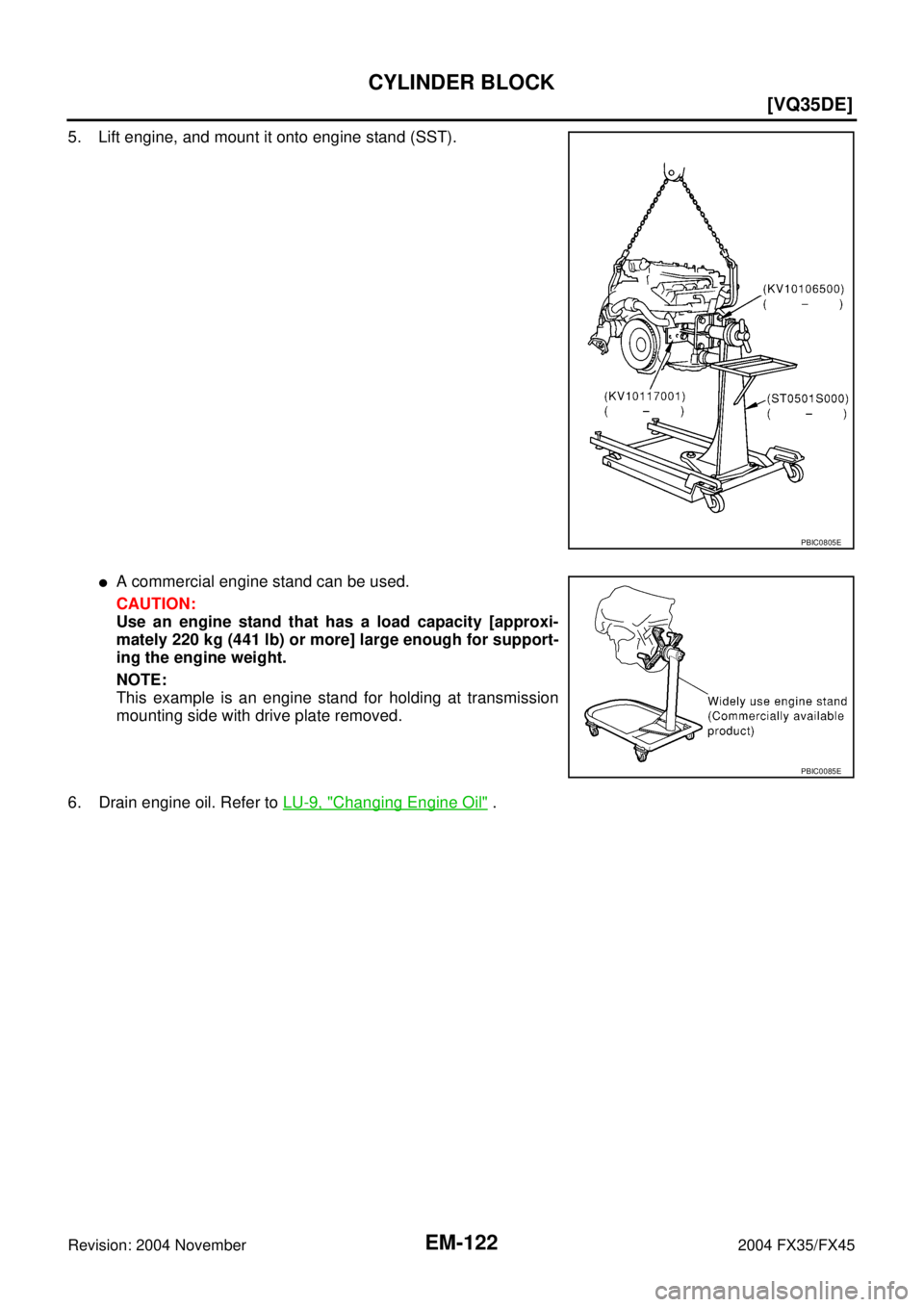
5. Lift engine, and mount it onto engine stand (SST).
�A commercial engine stand can be used.
CAUTION:
Use an engine stand that has a load capacity [approxi-
mately 220 kg (441 lb) or more] large enough for support-
ing the engine weight.
NOTE:
This example is an engine stand for holding at transmission
mounting side with drive plate removed.
6. Drain engine oil. Refer to LU-9, "
Changing Engine Oil" .
PBIC0805E
PBIC0085E
Page 2924 of 4449
![INFINITI FX35 2004 Service Manual TIMING CHAIN
EM-199
[VK45DE]
C
D
E
F
G
H
I
J
K
L
MA
EM
Revision: 2004 November 2004 FX35/FX45
a. Remove rear plate cover, and set ring gear stopper (SST).
b. Loosen crankshaft pulley bolt, and then pu](/manual-img/42/57021/w960_57021-2923.png "INFINITI FX35 2004 Service Manual TIMING CHAIN
EM-199
[VK45DE]
C
D
E
F
G
H
I
J
K
L
MA
EM
Revision: 2004 November 2004 FX35/FX45
a. Remove rear plate cover, and set ring gear stopper (SST).
b. Loosen crankshaft pulley bolt, and then pu")
TIMING CHAIN
EM-199
[VK45DE]
C
D
E
F
G
H
I
J
K
L
MA
EM
Revision: 2004 November 2004 FX35/FX45
a. Remove rear plate cover, and set ring gear stopper (SST).
b. Loosen crankshaft pulley bolt, and then pull crankshaft pulley
with both hands to remove it.
CAUTION:
�Do not remove crankshaft pulley bolt. Keep loosened
crankshaft pulley bolt in place to protect removed crank-
shaft pulley from dropping.
�Do not remove balance weight (inner hexagon bolt) at the
front of crankshaft pulley.
9. Remove oil pan and oil strainer. Refer to EM-181, "
OIL PAN AND OIL STRAINER" .
10. Remove front cover as follows:
a. Loosen mounting bolts in reverse order as shown in the figure.
b . U s e s e a l c u t t e r [ S S T: K V 1 0 1111 0 0 ( J 3 7 2 2 8 ) ] o r e q u i v a l e n t t o o l
to cut liquid gasket for removal.
CAUTION:
�Exercise care not to damage mating surfaces.
�After removal, handle front cover carefully so it does not
tilt, cant, or warp under a load.
11. Remove front oil seal from front cover using suitable tool.
�Use flat-blade screwdriver for removal.
CAUTION:
Be careful not to damage front cover.
12. Remove O-rings from cylinder heads (right and left bank) and
cylinder block.
13. Remove chain tensioner cover from front cover.
�U s e s e a l c u t t e r [ S S T: K V 1 0 1111 0 0 ( J 3 7 2 2 8 ) ] o r e q u i v a l e n t t o o l t o c u t l i q u i d g a s k e t f o r r e m o v e .
14. Remove oil pump drive spacer.
�Set bolts in the two bolt holes [M6 × pitch 1.0 mm (0.04 in)] on
front surface. Using suitable puller, pull oil pump drive spacer
off from crankshaft.
NOTE:
The dimension between the centers of the two bolt holes is 33
mm (1.30 in).
In the figure, a commercial steering puller is used.
15. Remove oil pump. Refer to LU-31, "
OIL PUMP" .
16. Remove chain tensioner (left bank) as follows:
PBIC1656E
KBIA0354J
SBIA0373E
PBIC2342E
![INFINITI FX35 2004 Service Manual EC-1166
[VK45DE]
DTC P1444 EVAP CANISTER PURGE VOLUME CONTROL SOLENOID VALVE
Revision: 2004 November 2004 FX35/FX45
10. CHECK IF EVAP CANISTER SATURATED WITH WATER
1. Remove EVAP canister with EVAP ca](/manual-img/42/57021/w960_57021-2506.png "INFINITI FX35 2004 Service Manual EC-1166
[VK45DE]
DTC P1444 EVAP CANISTER PURGE VOLUME CONTROL SOLENOID VALVE
Revision: 2004 November 2004 FX35/FX45
10. CHECK IF EVAP CANISTER SATURATED WITH WATER
1. Remove EVAP canister with EVAP ca")