Page 4077 of 4449

RSU-18
SERVICE DATA
Revision: 2004 November 2004 FX35/FX45
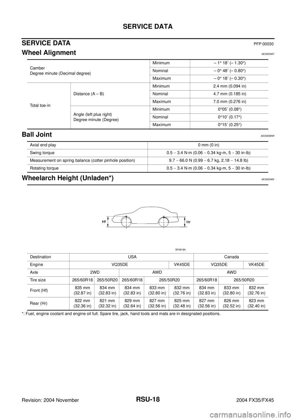
SERVICE DATAPFP:00030
Wheel AlignmentAES000MV
Ball JointAES000MW
Wheelarch Height (Unladen*)AES000MX
*: Fuel, engine coolant and engine oil full. Spare tire, jack, hand tools and mats are in designated positions.Camber
Degree minute (Decimal degree)Minimum – 1° 18′ (– 1.30°)
Nominal – 0° 48′ (– 0.80°)
Maximum – 0° 18′ (– 0.30°)
Total toe-inDistance (A – B)Minimum 2.4 mm (0.094 in)
Nominal 4.7 mm (0.185 in)
Maximum 7.0 mm (0.276 in)
Angle (left plus right)
Degree minute (Degree)Minimum 0°05′ (0.08°)
Nominal 0°10′ (0.17°)
Maximum 0°15′ (0.25°)
Axial end play0 mm (0 in)
Swing torque 0.5 − 3.4 N·m (0.06 − 0.34 kg-m, 5 − 30 in-lb)
Measurement on spring balance (cotter pinhole position) 9.7 − 66.0 N (0.99 − 6.7 kg, 2.18 − 14.8 lb)
Rotating torque 0.5 − 3.4 N·m (0.06 − 0.34 kg-m, 5 − 30 in-lb)
Destination USA Canada
Engine VQ35DE VK45DE VQ35DE VK45DE
Axle 2WD AWD AWD
Tire size 265/60R18 265/50R20 265/60R18 265/50R20 265/60R18 265/50R20
Front (Hf)835 mm
(32.87 in)834 mm
(32.83 in)834 mm
(32.83 in)833 mm
(32.80 in)832 mm
(32.76 in)834 mm
(32.83 in)833 mm
(32.80 in)832 mm
(32.76 in)
Rear (Hr)822 mm
(32.36 in)821 mm
(32.32 in)829 mm
(32.64 in)827 mm
(32.56 in)825 mm
(32.48 in)827 mm
(32.56 in)826 mm
(32.52 in)823 mm
(32.40 in)
SFA818A
Page 4090 of 4449

SC-1
STARTING & CHARGING SYSTEM
K ELECTRICAL
CONTENTS
C
D
E
F
G
H
I
J
L
M
SECTION SC
A
B
SC
Revision: 2004 November 2004 FX35/FX45
STARTING & CHARGING SYSTEM
PRECAUTIONS .......................................................... 2
Precautions for Supplemental Restraint System
(SRS) “AIR BAG” and “SEAT BELT PRE-TEN-
SIONER” .................................................................. 2
Wiring Diagrams and Trouble Diagnosis .................. 2
PREPARATION ........................................................... 3
Special Service Tools ............................................... 3
Commercial Service Tools ........................................ 3
BATTERY .................................................................... 4
How to Handle Battery ............................................. 4
METHODS OF PREVENTING OVER-DIS-
CHARGE ............................................................... 4
CHECKING ELECTROLYTE LEVEL .................... 5
SPECIFIC GRAVITY CHECK ............................... 5
CHARGING THE BATTERY ................................. 6
Trouble Diagnosis with Battery/Starting/Charging
System Tester .......................................................... 6
DIAGNOSTIC RESULT ITEM CHART .................. 8
Removal and Installation .......................................... 9
REMOVAL ............................................................. 9
INSTALLATION ..................................................... 9
STARTING SYSTEM ................................................ 10
System Description ................................................ 10
Wiring Diagram — START — .................................. 11
VK45DE ENGINE MODELS ................................ 11
VQ35DE ENGINE MODELS ............................... 12
Trouble Diagnosis with Battery/Starting/Charging
System Tester ........................................................ 13
DIAGNOSTIC RESULT ITEM CHART ................ 13
WORK FLOW ...................................................... 14
DIAGNOSTIC PROCEDURE 1 ........................... 15
DIAGNOSTIC PROCEDURE 2 ........................... 16
MINIMUM SPECIFICATION OF CRANKING VOLTAGE REFERENCING COOLANT TEM-
PERATURE ......................................................... 16
Removal and Installation ........................................ 17
VK45DE ENGINE MODELS ................................ 17
VQ35DE ENGINE MODELS (2WD) .................... 18
VQ35DE ENGINE MODELS (AWD) .................... 19
Disassembly and Assembly .................................... 20
Inspection After Disassembly ................................. 22
PINION/CLUTCH CHECK ................................... 22
CHARGING SYSTEM ............................................... 23
System Description ................................................. 23
Wiring Diagram — CHARGE — ............................. 24
VK45DE ENGINE MODELS ................................ 24
VQ35DE ENGINE MODELS ............................... 25
Trouble Diagnosis with Battery/Starting/Charging
System Tester ......................................................... 26
DIAGNOSTIC RESULT ITEM CHART ................ 27
WORK FLOW ...................................................... 28
DIAGNOSTIC PROCEDURE 1 ........................... 29
DIAGNOSTIC PROCEDURE 2 ........................... 30
DIAGNOSTIC PROCEDURE 3 ........................... 31
DIAGNOSTIC PROCEDURE 4 ........................... 32
DIAGNOSTIC PROCEDURE 5 ........................... 33
MALFUNCTION INDICATOR .............................. 33
Removal and Installation ........................................ 34
VK45DE ENGINE MODELS ................................ 34
VQ35DE ENGINE MODELS ............................... 35
Disassembly and Assembly .................................... 37
SERVICE DATA AND SPECIFICATIONS (SDS) ...... 39
Battery .................................................................... 39
Starter ..................................................................... 39
Alternator ................................................................ 39
Page 4093 of 4449

SC-4
BATTERY
Revision: 2004 November 2004 FX35/FX45
BATTERYPFP:AYBGL
How to Handle BatteryAKS00799
CAUTION:
�If it becomes necessary to start the engine with a booster battery and jumper cables, use a 12-volt
booster battery.
�After connecting battery cables, ensure that they are tightly clamped to battery terminals for good
contact.
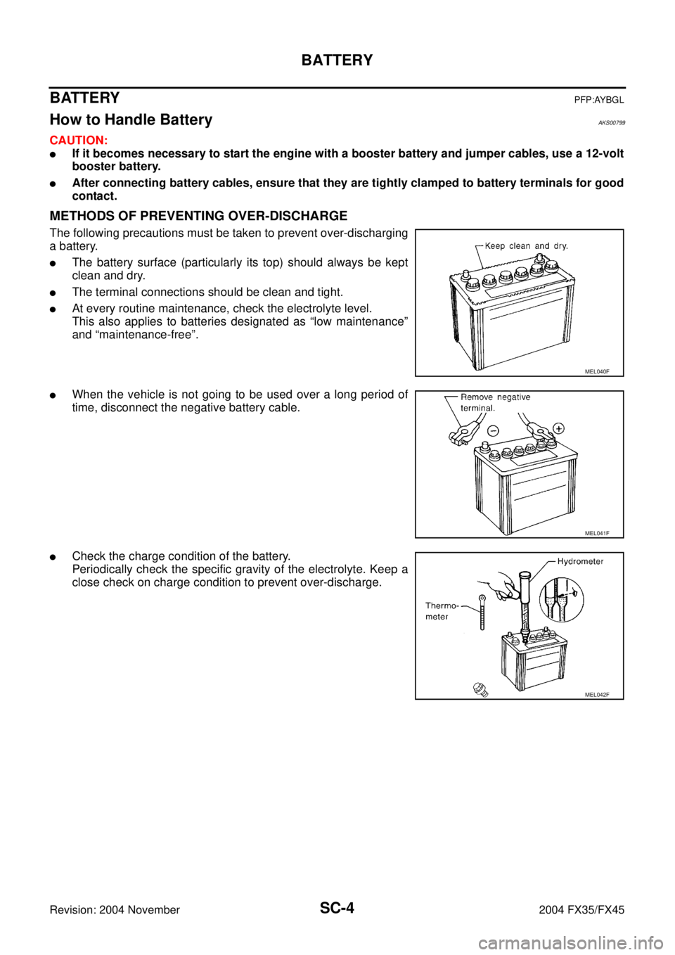
METHODS OF PREVENTING OVER-DISCHARGE
The following precautions must be taken to prevent over-discharging
a battery.
�The battery surface (particularly its top) should always be kept
clean and dry.
�The terminal connections should be clean and tight.
�At every routine maintenance, check the electrolyte level.
This also applies to batteries designated as “low maintenance”
and “maintenance-free”.
�When the vehicle is not going to be used over a long period of
time, disconnect the negative battery cable.
�Check the charge condition of the battery.
Periodically check the specific gravity of the electrolyte. Keep a
close check on charge condition to prevent over-discharge.
MEL040F
MEL041F
MEL042F
Page 4099 of 4449

SC-10
STARTING SYSTEM
Revision: 2004 November 2004 FX35/FX45
STARTING SYSTEMPFP:23300
System Description AKS0079C
Power is supplied at all times:
�through 40A fusible link (letter F, located in the fuse and fusible link box)
�to ignition switch terminal 1
�through 15A fuse (No. 78, located in the IPDM E/R)
�to CPU of IPDM E/R
�through 10A fuse (No. 71, located in the IPDM E/R)
�to CPU of IPDM E/R.
When the selector lever in the P or N position, power is supplied:
�from TCM, and through A/T assembly terminal 9
�to IPDM E/R terminal 53.
Ground is supplied:
�to IPDM E/R terminals 38, 50 and 60
�from body grounds E21, E50 and E51.
With the ignition switch in the START position, and provided that the IPDM E/R receives a starter relay ON sig-
nal from the CAN lines, the IPDM E/R is energized and power is supplied:
�from ignition switch terminal 5
�to IPDM E/R terminal 4 and
�through IPDM E/R terminal 3
�to starter motor terminal 1.
The starter motor plunger closes and provides a closed circuit between the battery and starter motor. The
starter motor is grounded to the engine block. With power and ground supplied, cranking occurs and the
engine starts.
Page 4100 of 4449
STARTING SYSTEM
SC-11
C
D
E
F
G
H
I
J
L
MA
B
SC
Revision: 2004 November 2004 FX35/FX45
Wiring Diagram — START —AKS0079D
VK45DE ENGINE MODELS
TKWM1275E
Page 4101 of 4449
SC-12
STARTING SYSTEM
Revision: 2004 November 2004 FX35/FX45
VQ35DE ENGINE MODELS
TKWM1276E
Page 4102 of 4449

STARTING SYSTEM
SC-13
C
D
E
F
G
H
I
J
L
MA
B
SC
Revision: 2004 November 2004 FX35/FX45
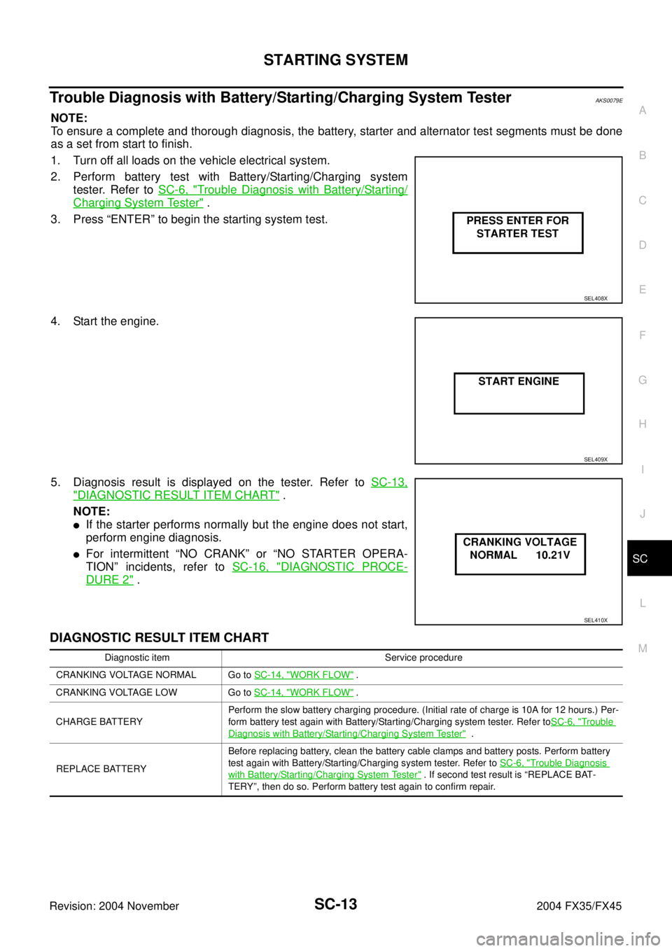
Trouble Diagnosis with Battery/Starting/Charging System TesterAKS0079E
NOTE:
To ensure a complete and thorough diagnosis, the battery, starter and alternator test segments must be done
as a set from start to finish.
1. Turn off all loads on the vehicle electrical system.
2. Perform battery test with Battery/Starting/Charging system
tester. Refer to SC-6, "
Trouble Diagnosis with Battery/Starting/
Charging System Tester" .
3. Press “ENTER” to begin the starting system test.
4. Start the engine.
5. Diagnosis result is displayed on the tester. Refer to SC-13,
"DIAGNOSTIC RESULT ITEM CHART" .
NOTE:
�If the starter performs normally but the engine does not start,
perform engine diagnosis.
�For intermittent “NO CRANK” or “NO STARTER OPERA-
TION” incidents, refer to SC-16, "
DIAGNOSTIC PROCE-
DURE 2" .
DIAGNOSTIC RESULT ITEM CHART
SEL408X
SEL409X
SEL410X
Diagnostic item Service procedure
CRANKING VOLTAGE NORMAL Go to SC-14, "
WORK FLOW" .
CRANKING VOLTAGE LOW Go to SC-14, "
WORK FLOW" .
CHARGE BATTERYPerform the slow battery charging procedure. (Initial rate of charge is 10A for 12 hours.) Per-
form battery test again with Battery/Starting/Charging system tester. Refer toSC-6, "
Trouble
Diagnosis with Battery/Starting/Charging System Tester" .
REPLACE BATTERYBefore replacing battery, clean the battery cable clamps and battery posts. Perform battery
test again with Battery/Starting/Charging system tester. Refer to SC-6, "
Trouble Diagnosis
with Battery/Starting/Charging System Tester" . If second test result is “REPLACE BAT-
TERY”, then do so. Perform battery test again to confirm repair.
Page 4104 of 4449

STARTING SYSTEM
SC-15
C
D
E
F
G
H
I
J
L
MA
B
SC
Revision: 2004 November 2004 FX35/FX45
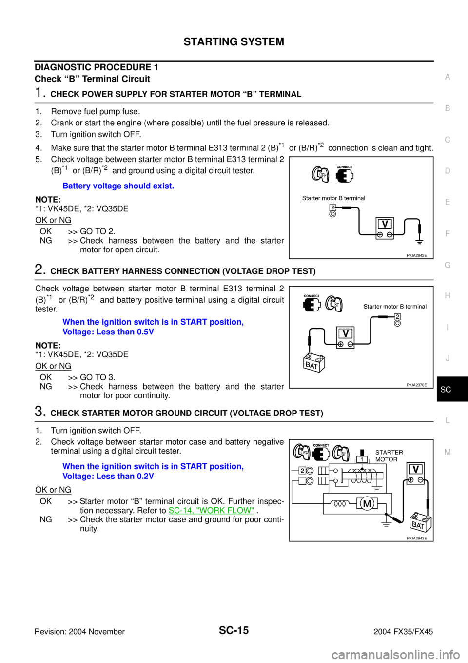
DIAGNOSTIC PROCEDURE 1
Check “B” Terminal Circuit
1. CHECK POWER SUPPLY FOR STARTER MOTOR “B” TERMINAL
1. Remove fuel pump fuse.
2. Crank or start the engine (where possible) until the fuel pressure is released.
3. Turn ignition switch OFF.
4. Make sure that the starter motor B terminal E313 terminal 2 (B)
*1 or (B/R)*2 connection is clean and tight.
5. Check voltage between starter motor B terminal E313 terminal 2
(B)
*1 or (B/R)*2 and ground using a digital circuit tester.
NOTE:
*1: VK45DE, *2: VQ35DE
OK or NG
OK >> GO TO 2.
NG >> Check harness between the battery and the starter
motor for open circuit.
2. CHECK BATTERY HARNESS CONNECTION (VOLTAGE DROP TEST)
Check voltage between starter motor B terminal E313 terminal 2
(B)
*1 or (B/R)*2 and battery positive terminal using a digital circuit
tester.
NOTE:
*1: VK45DE, *2: VQ35DE
OK or NG
OK >> GO TO 3.
NG >> Check harness between the battery and the starter
motor for poor continuity.
3. CHECK STARTER MOTOR GROUND CIRCUIT (VOLTAGE DROP TEST)
1. Turn ignition switch OFF.
2. Check voltage between starter motor case and battery negative
terminal using a digital circuit tester.
OK or NG
OK >> Starter motor “B” terminal circuit is OK. Further inspec-
tion necessary. Refer to SC-14, "
WORK FLOW" .
NG >> Check the starter motor case and ground for poor conti-
nuity. Battery voltage should exist.
PKIA2842E
When the ignition switch is in START position,
Voltage: Less than 0.5V
PKIA2370E
When the ignition switch is in START position,
Voltage: Less than 0.2V
PKIA2943E