Page 2803 of 4449
EM-78
[VQ35DE]
TIMING CHAIN
Revision: 2004 November 2004 FX35/FX45
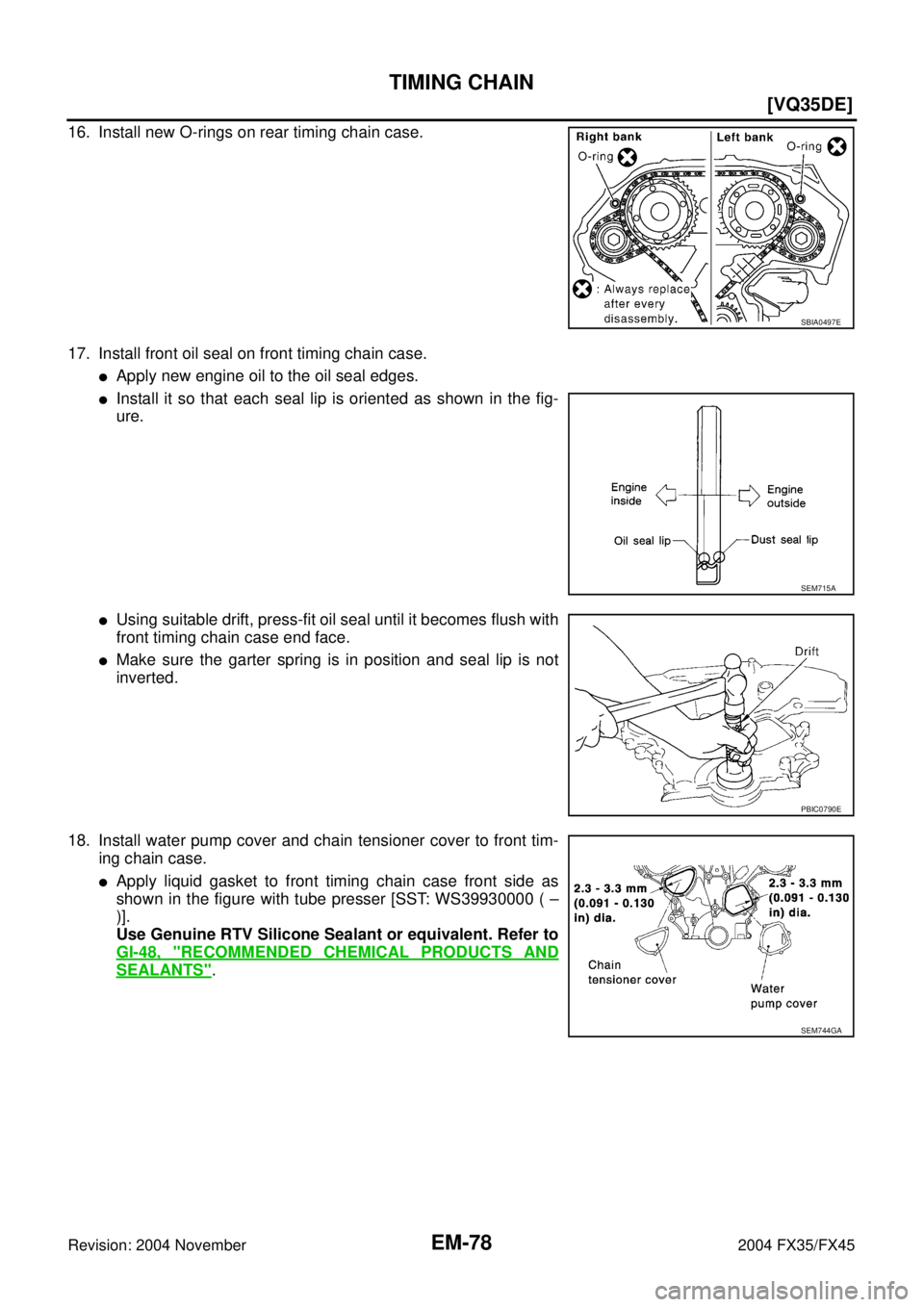
16. Install new O-rings on rear timing chain case.
17. Install front oil seal on front timing chain case.
�Apply new engine oil to the oil seal edges.
�Install it so that each seal lip is oriented as shown in the fig-
ure.
�Using suitable drift, press-fit oil seal until it becomes flush with
front timing chain case end face.
�Make sure the garter spring is in position and seal lip is not
inverted.
18. Install water pump cover and chain tensioner cover to front tim-
ing chain case.
�Apply liquid gasket to front timing chain case front side as
shown in the figure with tube presser [SST: WS39930000 ( –
)].
Use Genuine RTV Silicone Sealant or equivalent. Refer to
GI-48, "
RECOMMENDED CHEMICAL PRODUCTS AND
SEALANTS".
SBIA0497E
SEM715A
PBIC0790E
SEM744GA
Page 2805 of 4449
![INFINITI FX35 2004 Service Manual EM-80
[VQ35DE]
TIMING CHAIN
Revision: 2004 November 2004 FX35/FX45
c. Install collared O-ring in front cover engine oil hole (left and right
sides).
d. Being careful not to move seal ring from the ins](/manual-img/42/57021/w960_57021-2804.png "INFINITI FX35 2004 Service Manual EM-80
[VQ35DE]
TIMING CHAIN
Revision: 2004 November 2004 FX35/FX45
c. Install collared O-ring in front cover engine oil hole (left and right
sides).
d. Being careful not to move seal ring from the ins")
EM-80
[VQ35DE]
TIMING CHAIN
Revision: 2004 November 2004 FX35/FX45
c. Install collared O-ring in front cover engine oil hole (left and right
sides).
d. Being careful not to move seal ring from the installation groove,
align dowel pins on chain case with the holes to install intake
valve timing control covers.
e. Tighten bolts in the numerical order as shown in the figure.
22. Install crankshaft pulley as follows:
a. Fix crankshaft using ring gear stopper [SST: KV10117700 (J-44716)].
b. Install crankshaft pulley, taking care not to damage front oil seal.
�When press-fitting crankshaft pulley with a plastic hammer, tap on its center portion (not circumfer-
ence).
c. Tighten bolt.
d. Put a paint mark on crankshaft pulley aligning with angle mark
on crankshaft pulley bolt. Then, further retighten bolt by “60”
degrees (equivalent to one graduation).
23. Rotate crankshaft pulley in normal direction (clockwise when viewed from front) to confirm it turns
smoothly.
24. For the following operations, perform steps in the reverse order of removal.
NOTE:
If hydraulic pressure inside chain tensioner drops after removal/installation, slack in guide may generate a
pounding noise during and just after engine start. However, this does not indicate an unusualness. Noise
will stop after hydraulic pressure rises.
INSPECTION AFTER INSTALLATION
�Before starting engine, check the levels of engine coolant, lubrications and working fluid. If less than
required quantity, fill to the specified level.
�Run engine to check for unusual noise and vibration.
PBIC2045E
PBIC0918E
: 44.1 N·m (4.5 kg-m, 33 ft-lb)
SEM751G
Page 2806 of 4449
TIMING CHAIN
EM-81
[VQ35DE]
C
D
E
F
G
H
I
J
K
L
MA
EM
Revision: 2004 November 2004 FX35/FX45
�Warm up engine thoroughly to make sure there is no leakage of engine coolant, engine oil and working
fluid, fuel and exhaust gas.
�Bleed air from passages in pipes and tubes of applicable lines, such as in cooling system.
�After cooling down engine, again check amounts of engine coolant, engine oil and working fluid. Refill to
specified level, if necessary.
Summary of the inspection items:
Item Before starting engine Engine running After engine stopped
Engine coolant Level Leakage Level
Engine oil Level Leakage Level
Working fluid Level Leakage Level
Page 2819 of 4449
![INFINITI FX35 2004 Service Manual EM-94
[VQ35DE]
OIL SEAL
Revision: 2004 November 2004 FX35/FX45
OIL SEALPFP:00100
Removal and Installation of Valve Oil SealABS004X4
REMOVAL
1. Remove camshaft relating to valve oil seal to be removed.](/manual-img/42/57021/w960_57021-2818.png "INFINITI FX35 2004 Service Manual EM-94
[VQ35DE]
OIL SEAL
Revision: 2004 November 2004 FX35/FX45
OIL SEALPFP:00100
Removal and Installation of Valve Oil SealABS004X4
REMOVAL
1. Remove camshaft relating to valve oil seal to be removed.")
EM-94
[VQ35DE]
OIL SEAL
Revision: 2004 November 2004 FX35/FX45
OIL SEALPFP:00100
Removal and Installation of Valve Oil SealABS004X4
REMOVAL
1. Remove camshaft relating to valve oil seal to be removed. Refer to EM-82, "CAMSHAFT" .
2. Remove valve lifters. Refer to EM-82, "
CAMSHAFT" .
3. Turn crankshaft until the cylinder requiring new oil seals is at TDC. This will prevent valve from dropping
into cylinder.
4. Using valve spring compressor, attachment and adapter (SST),
remove valve collet with magnet hand. Then remove valve
spring and valve spring seat.
5. Remove valve oil seal using valve oil seal puller (SST).
INSTALLATION
1. Apply engine oil on new valve oil seal joint and seal lip.
2. Using valve oil seal drift (SST), press fit valve seal to height “H”
shown in the figure.
NOTE:
Dimension “H”: Height measured before valve spring seat instal-
lation
3. Perform steps in the reverse order of removal for the following operations.
PBIC1803E
PBIC0884E
Intake and exhaust : 14.3 - 14.9 mm (0.563 - 0.587 in)
PBIC0802E
Page 2820 of 4449
![INFINITI FX35 2004 Service Manual OIL SEAL
EM-95
[VQ35DE]
C
D
E
F
G
H
I
J
K
L
MA
EM
Revision: 2004 November 2004 FX35/FX45
Removal and Installation of Front Oil SealABS004X5
REMOVAL
1. Remove the following parts:
�Front engine underco](/manual-img/42/57021/w960_57021-2819.png "INFINITI FX35 2004 Service Manual OIL SEAL
EM-95
[VQ35DE]
C
D
E
F
G
H
I
J
K
L
MA
EM
Revision: 2004 November 2004 FX35/FX45
Removal and Installation of Front Oil SealABS004X5
REMOVAL
1. Remove the following parts:
�Front engine underco")
OIL SEAL
EM-95
[VQ35DE]
C
D
E
F
G
H
I
J
K
L
MA
EM
Revision: 2004 November 2004 FX35/FX45
Removal and Installation of Front Oil SealABS004X5
REMOVAL
1. Remove the following parts:
�Front engine undercover (With power tool)
�Drive belt; Refer to EM-15, "DRIVE BELTS" .
2. Remove crankshaft pulley with the following procedure:
a. Remove rear cover plate (2WD) or starter motor (AWD) and set
ring gear stopper (SST) as shown in the figure. Refer to SC-10,
"STARTING SYSTEM" .
b. Loosen crankshaft pulley bolt and locate bolt seating surface as
10 mm (0.39 in) from its original position.
CAUTION:
Do not remove crankshaft pulley bolt as it will be used as a
supporting point for suitable puller.
c. Place suitable puller tab on holes of crankshaft pulley, and pull
crankshaft pulley through.
CAUTION:
Do not put suitable puller tab on crankshaft pulley periph-
ery, as this will damage internal damper.
3. Remove front oil seal using a suitable tool.
CAUTION:
Be careful not to damage front timing chain case and crank-
shaft.
PBIC1098E
PBIC1103E
EMQ0477D
SEM829E
Page 2821 of 4449
![INFINITI FX35 2004 Service Manual EM-96
[VQ35DE]
OIL SEAL
Revision: 2004 November 2004 FX35/FX45
INSTALLATION
1. Apply engine oil on new front oil seal.
2. Using a suitable drift, press fit until the height of front oil seal is
level](/manual-img/42/57021/w960_57021-2820.png "INFINITI FX35 2004 Service Manual EM-96
[VQ35DE]
OIL SEAL
Revision: 2004 November 2004 FX35/FX45
INSTALLATION
1. Apply engine oil on new front oil seal.
2. Using a suitable drift, press fit until the height of front oil seal is
level")
EM-96
[VQ35DE]
OIL SEAL
Revision: 2004 November 2004 FX35/FX45
INSTALLATION
1. Apply engine oil on new front oil seal.
2. Using a suitable drift, press fit until the height of front oil seal is
level with the mounting surface.
�Suitable drift: outer diameter 59 mm (2.32 in), inner diameter
49 mm (1.93 in).
CAUTION:
Press fit straight and avoid causing burrs or tilting oil
seal.
3. Perform steps in the reverse order of removal for the following operations.
Removal and Installation of Rear Oil SealABS004X6
REMOVAL
1. Remove oil pan (upper). Refer to EM-30, "OIL PAN AND OIL STRAINER" .
2. Remove transmission assembly. Refer to AT- 2 6 6 , "
TRANSMISSION ASSEMBLY" .
3. Remove drive plate with power tool. Fix crankshaft with a ring gear stopper [SST: KV1011770 (J-44716)],
and remove mounting bolts.
�Loosen mounting bolts in diagonal order.
CAUTION:
�Do not disassemble drive plate.
�Never place drive plate with signal plate facing down.
�When handling signal plate, take care not to damage or
scratch it.
�Handle signal plate in a manner that prevents it from
becoming magnetized.
4. Use a seal cutter (SST) to cut away liquid gasket and remove
rear oil seal retainer.
CAUTION:
Be careful not to damage mounting surface.
NOTE:
Rear oil seal and retainer form a single part and are handled as
an assembly.
INSTALLATION
1. Remove old liquid gasket on mating surface of cylinder block and oil pan using scraper.
SEM715A
SEM760G
SEM830E
Page 2822 of 4449
OIL SEAL
EM-97
[VQ35DE]
C
D
E
F
G
H
I
J
K
L
MA
EM
Revision: 2004 November 2004 FX35/FX45
2. Apply new engine oil to the oil and dust seal lips.
3. Apply liquid gasket to rear oil seal retainer with tube presser
[SST: WS39930000 ( – )] as shown in the figure.
Use Genuine RTV Silicone Sealant or equivalent. Refer to
GI-48, "
RECOMMENDED CHEMICAL PRODUCTS AND
SEALANTS" .
�Assembly should be done within 5 minutes after coating.
4. Install rear oil seal retainer to cylinder block.
5. Perform steps in the reverse order of removal for the following operations.
PBIC0922E
Page 2823 of 4449
![INFINITI FX35 2004 Service Manual EM-98
[VQ35DE]
CYLINDER HEAD
Revision: 2004 November 2004 FX35/FX45
CYLINDER HEADPFP:11041
On-Vehicle ServiceABS004X7
CHECKING COMPRESSION PRESSURE
1. Warm up engine thoroughly. Then, stop it.
2. Rele](/manual-img/42/57021/w960_57021-2822.png "INFINITI FX35 2004 Service Manual EM-98
[VQ35DE]
CYLINDER HEAD
Revision: 2004 November 2004 FX35/FX45
CYLINDER HEADPFP:11041
On-Vehicle ServiceABS004X7
CHECKING COMPRESSION PRESSURE
1. Warm up engine thoroughly. Then, stop it.
2. Rele")
EM-98
[VQ35DE]
CYLINDER HEAD
Revision: 2004 November 2004 FX35/FX45
CYLINDER HEADPFP:11041
On-Vehicle ServiceABS004X7
CHECKING COMPRESSION PRESSURE
1. Warm up engine thoroughly. Then, stop it.
2. Release fuel pressure. Refer to EC-51, "
FUEL PRESSURE RELEASE" .
3. Disconnect fuel pump fuse to avoid fuel injection during mea-
surement.
4. Remove engine cover with power tool. Refer to EM-19, "
INTAKE MANIFOLD COLLECTOR" .
5. Remove ignition coil and spark plug from each cylinder. Refer to EM-42, "
IGNITION COIL" and EM-43,
"SPARK PLUG (PLATINUM-TIPPED TYPE)" .
6. Connect engine tachometer (not required in use of CONSULT-ll).
7. Install compression gauge with compression gauge adapter
(commercial service tool) onto spark plug hole.
�Use compression gauge adapter whose picking up end
inserted to spark plug hole is smaller than 20 mm (0.79 in) in
diameter. Otherwise, it may be caught by cylinder head during
removal.
8. With accelerator pedal fully depressed, turn ignition switch to
“START” for cranking. When gauge pointer stabilizes, read the
compression pressure and engine rpm. Perform these steps to
check each cylinder.
Compression pressure:
Unit: kPa (kg/cm2 , psi) /rpm
CAUTION:
Always use a fully changed battery to obtain specified engine speed.
�If engine speed is out of specified range, check battery liquid for proper gravity. Check engine speed
again with normal battery gravity.
SBIA0466E
PBIC0900E
SBIA0533E
Standard Minimum Deference limit between cylinders
1,275 (13.0, 185) / 300 981 (10.0, 142) / 300 98 (1.0, 14) / 300

![INFINITI FX35 2004 Service Manual OIL SEAL
EM-97
[VQ35DE]
C
D
E
F
G
H
I
J
K
L
MA
EM
Revision: 2004 November 2004 FX35/FX45
2. Apply new engine oil to the oil and dust seal lips.
3. Apply liquid gasket to rear oil seal retainer with tu](/manual-img/42/57021/w960_57021-2821.png "INFINITI FX35 2004 Service Manual OIL SEAL
EM-97
[VQ35DE]
C
D
E
F
G
H
I
J
K
L
MA
EM
Revision: 2004 November 2004 FX35/FX45
2. Apply new engine oil to the oil and dust seal lips.
3. Apply liquid gasket to rear oil seal retainer with tu")