Page 4064 of 4449

REAR SUSPENSION ASSEMBLY
RSU-5
C
D
F
G
H
I
J
K
L
MA
B
RSU
Revision: 2004 November 2004 FX35/FX45
REAR SUSPENSION ASSEMBLYPFP:55020
On-Vehicle Inspection and ServiceAES000MJ
Make sure the mounting conditions (looseness, back lash) of each component and component status (wear,
damage) are normal.
INSPECTION OF SUSPENSION ARM BALL JOINT END PLAY
Measure axial end play by installing and moving up/down between suspension arm and axle with an iron pry
bar or something similar.
CAUTION:
Be careful not to damage ball joint boot.
SHOCK ABSORBER INSPECTION
Check shock absorber for oil leakage, damage and replace if necessary.
Wheel Alignment InspectionAES000MK
DESCRIPTION
Measure wheel alignment under unladen conditions. “Unladen conditions” mean that fuel, engine coolant, and
lubricant are full. Spare tire, jack, hand tools and mats are in designated positions.
PRELIMINARY CHECK
1. Check tires for improper air pressure and wear.
2. Check road wheels for runout.
3. Check wheel bearing axial end play.
4. Check suspension arm ball joint axial end play.
5. Check shock absorber operation.
6. Check each mounting part of axle and suspension for looseness and deformation.
7. Check each link, arm and member for cracks, deformation, and other damage.
8. Check vehicle posture.
CAMBER INSPECTION
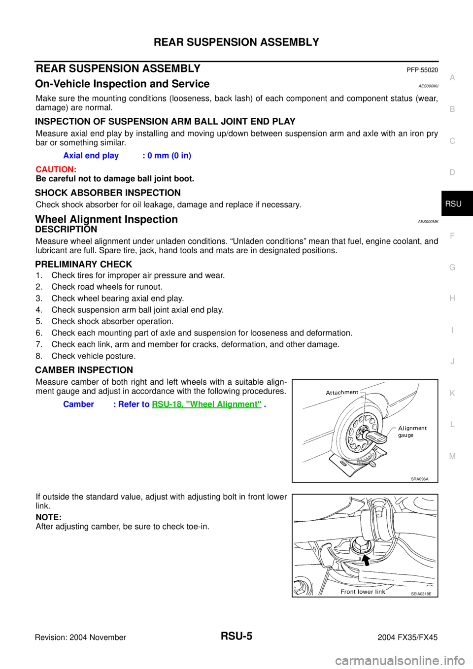
Measure camber of both right and left wheels with a suitable align-
ment gauge and adjust in accordance with the following procedures.
If outside the standard value, adjust with adjusting bolt in front lower
link.
NOTE:
After adjusting camber, be sure to check toe-in.Axial end play : 0 mm (0 in)
Camber : Refer to RSU-18, "
Wheel Alignment" .
SRA096A
SEIA0318E
Page 4077 of 4449

RSU-18
SERVICE DATA
Revision: 2004 November 2004 FX35/FX45
SERVICE DATAPFP:00030
Wheel AlignmentAES000MV
Ball JointAES000MW
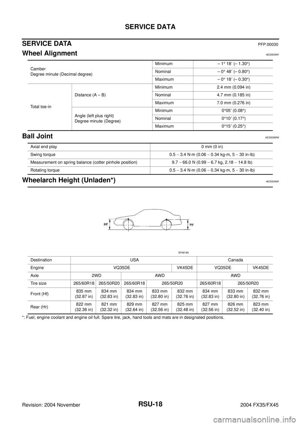
Wheelarch Height (Unladen*)AES000MX
*: Fuel, engine coolant and engine oil full. Spare tire, jack, hand tools and mats are in designated positions.Camber
Degree minute (Decimal degree)Minimum – 1° 18′ (– 1.30°)
Nominal – 0° 48′ (– 0.80°)
Maximum – 0° 18′ (– 0.30°)
Total toe-inDistance (A – B)Minimum 2.4 mm (0.094 in)
Nominal 4.7 mm (0.185 in)
Maximum 7.0 mm (0.276 in)
Angle (left plus right)
Degree minute (Degree)Minimum 0°05′ (0.08°)
Nominal 0°10′ (0.17°)
Maximum 0°15′ (0.25°)
Axial end play0 mm (0 in)
Swing torque 0.5 − 3.4 N·m (0.06 − 0.34 kg-m, 5 − 30 in-lb)
Measurement on spring balance (cotter pinhole position) 9.7 − 66.0 N (0.99 − 6.7 kg, 2.18 − 14.8 lb)
Rotating torque 0.5 − 3.4 N·m (0.06 − 0.34 kg-m, 5 − 30 in-lb)
Destination USA Canada
Engine VQ35DE VK45DE VQ35DE VK45DE
Axle 2WD AWD AWD
Tire size 265/60R18 265/50R20 265/60R18 265/50R20 265/60R18 265/50R20
Front (Hf)835 mm
(32.87 in)834 mm
(32.83 in)834 mm
(32.83 in)833 mm
(32.80 in)832 mm
(32.76 in)834 mm
(32.83 in)833 mm
(32.80 in)832 mm
(32.76 in)
Rear (Hr)822 mm
(32.36 in)821 mm
(32.32 in)829 mm
(32.64 in)827 mm
(32.56 in)825 mm
(32.48 in)827 mm
(32.56 in)826 mm
(32.52 in)823 mm
(32.40 in)
SFA818A
Page 4107 of 4449
SC-18
STARTING SYSTEM
Revision: 2004 November 2004 FX35/FX45
VQ35DE ENGINE MODELS (2WD)
Removal
1. Disconnect negative battery cable.
2. Remove engine rear undercover, using power tools.
3. Disconnect S connector.
4. Remove B terminal nut.
5. Remove starter motor mounting bolts and harness clip bracket,
using power tools.
6. Remove starter motor to the direction of under side the vehicle.
Installation
Install in the reverse order of removal.
CAUTION:
Be sure to tighten B terminal nut carefully.
1. Starter motor mounting bolt 2. Harness clip bracket 3. S connector
4. B terminal nut 5. B terminal harness 6. Starter motor
7. Oil pan
PKIA3127E
PKIA2812E
Page 4108 of 4449
STARTING SYSTEM
SC-19
C
D
E
F
G
H
I
J
L
MA
B
SC
Revision: 2004 November 2004 FX35/FX45
VQ35DE ENGINE MODELS (AWD)
Removal
1. Disconnect negative battery cable.
2. Remove engine front and rear undercover, using power tools.
3. Disconnect S connector.
4. Remove B terminal nut.
5. Remove starter motor mounting bolts.
6. Remove starter motor to the direction of under side the vehicle.
Installation
Install in the reverse order of removal.
CAUTION:
Be sure to tighten B terminal nut carefully.
1. Starter motor mounting bolt 2. Oil pan 3. Starter motor
4. B terminal harness 5. B terminal nut 6. S connector
PKIA2843E
PKIA2844E
Page 4125 of 4449
SC-36
CHARGING SYSTEM
Revision: 2004 November 2004 FX35/FX45
7. Remove oil pressure switch harness clip from alternator stay.
(2WD)
8. Disconnect oil pressure switch connector. (2WD)
9. Remove alternator stay mounting bolts and alternator stay, using
power tools.
10. Remove alternator mounting bolt, using power tools.
11. Remove alternator assembly to the direction of under side the vehicle.
Installation
Note the following, and install in the reverse order of removal.
�Install alternator, and check tension of belt. Refer to EM-15, "Checking Drive Belts" in “ENGINE
MECHANICAL (EM)” section.
CAUTION:
Be sure to tighten B terminal nut carefully.
PKIA1923E
Page 4303 of 4449

TF-2Revision: 2004 November 2004 FX35/FX45Engine Is Started .................................................... 34
DIAGNOSTIC PROCEDURE .............................. 34
Vehicle Does Not Enter AWD Mode Even Though
AWD Warning Lamp Turned To OFF ...................... 35
DIAGNOSTIC PROCEDURE .............................. 35
While Driving, AWD Warning Lamp Flashes Rapidly
(When Flashing In Approx. 1 Minute And Then Turn-
ing OFF) ................................................................. 36
While Driving, AWD Warning Lamp Flashes Slowly
(When Continuing To Flash Until Turning Ignition
Switch OFF) ............................................................ 36
DIAGNOSTIC PROCEDURE .............................. 36
AWD CONTROL UNIT .............................................. 38
Removal and Installation ........................................ 38
REMOVAL ........................................................... 38
INSTALLATION .................................................... 38
FRONT OIL SEAL ..................................................... 39
Removal and Installation ........................................ 39
REMOVAL ........................................................... 39
INSTALLATION .................................................... 39REAR OIL SEAL ....................................................... 40
Removal and Installation ......................................... 40
REMOVAL ............................................................ 40
INSTALLATION .................................................... 41
AIR BREATHER HOSE ............................................. 42
Removal and Installation ......................................... 42
TRANSFER ASSEMBLY ........................................... 43
Removal and Installation ......................................... 43
REMOVAL ............................................................ 43
INSTALLATION .................................................... 43
Components ............................................................ 44
Disassembly and Assembly .................................... 45
DISASSEMBLY .................................................... 45
INSPECTION ....................................................... 49
ASSEMBLY .......................................................... 49
SERVICE DATA AND SPECIFICATIONS (SDS) ...... 55
General Specifications ............................................ 55