Page 4270 of 4449

TROUBLE DIAGNOSIS
SRS-29
C
D
E
F
G
I
J
K
L
MA
B
SRS
Revision: 2004 November 2004 FX35/FX45
Trouble Diagnosis without CONSULT-IIAHS000HT
DIAGNOSTIC PROCEDURE 6
Inspecting SRS Malfunctioning Parts by Using “AIR BAG” Warning Lamp — Diagnosis Mode
NOTE:
SRS will not enter Diagnosis mode if no malfunction is detected in User mode.
1. Turn ignition switch ON.
2. After “AIR BAG” warning lamp lights for 7 seconds, turn ignition switch OFF within 1 second.
3. Wait more than 3 seconds.
4. Repeat the steps 1 to 3 twice. (Perform three times in all.)
5. Turn ignition switch ON.
SRS is now in Diagnosis mode.
“AIR BAG” warning lamp operates in Diagnosis mode as follows:
CURTAIN MODULE RH
[OPEN]�RH side curtain air bag module circuit is open. 1. Visually check the wiring harness
connection.
2. Replace the harness if it has visible
damage.
3. If the harness check result is OK,
replace the diagnosis sensor unit
and RH side curtain air bag module.
(Before disposal, it must be
deployed.) CURTAIN MODULE RH
[VB-SHORT]
�RH side curtain air bag module circuit is shorted to a power sup-
ply circuit.
CURTAIN MODULE RH
[GND-SHORT]
�RH side curtain air bag module circuit is shorted to ground.
CURTAIN MODULE RH
[SHORT]
�RH side curtain air bag module circuit is shorted between lines.
CONTROL UNIT
�Diagnosis sensor unit is malfunctioning. 1. Visually check the wiring harness
connection.
2. Replace the diagnosis sensor unit. Diagnostic item ExplanationRepair order
“Recheck SRS at each replacement”
Page 4275 of 4449
SRS-34
TROUBLE DIAGNOSIS
Revision: 2004 November 2004 FX35/FX45
Trouble Diagnosis: “AIR BAG” Warning Lamp Does Not Turn OFFAHS000HU
DIAGNOSTIC PROCEDURE 7
1. CHECK THE DEPLOYMENT OF AIR BAG MODULE
Is air bag module deployed?
YES or NO
YES >> Refer to SRS-56, "COLLISION DIAGNOSIS" .
NO >> GO TO 2.
2. CHECK THE AIR BAG FUSE
Check 10A fuse [No. 13, located in fuse block (J/B)].
Refer to PG-3, "
POWER SUPPLY ROUTING CIRCUIT" .
OK or NG
OK >> GO TO 4.
NG >> GO TO 3.
3. CHECK AIR BAG FUSE AGAIN
Replace “AIR BAG” fuse and turn ignition switch ON.
Does the
“AIR BAG” fuse blow again?
YES >> Repair main harness.
NO >>INSPECTION END
4. CHECK DIAGNOSIS SENSOR UNIT
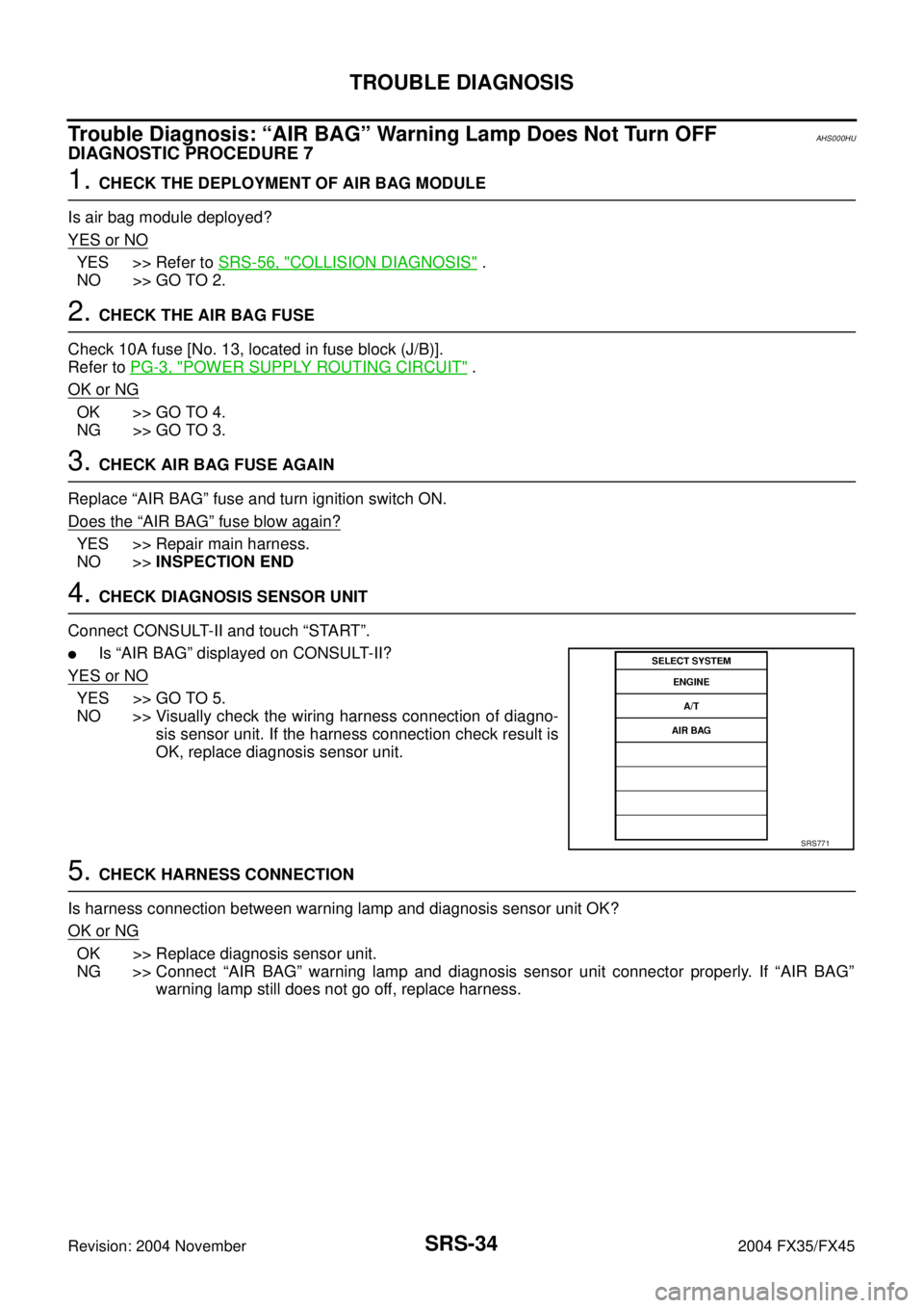
Connect CONSULT-II and touch “START”.
�Is “AIR BAG” displayed on CONSULT-II?
YES or NO
YES >> GO TO 5.
NO >> Visually check the wiring harness connection of diagno-
sis sensor unit. If the harness connection check result is
OK, replace diagnosis sensor unit.
5. CHECK HARNESS CONNECTION
Is harness connection between warning lamp and diagnosis sensor unit OK?
OK or NG
OK >> Replace diagnosis sensor unit.
NG >> Connect “AIR BAG” warning lamp and diagnosis sensor unit connector properly. If “AIR BAG”
warning lamp still does not go off, replace harness.
SRS771
Page 4276 of 4449
TROUBLE DIAGNOSIS
SRS-35
C
D
E
F
G
I
J
K
L
MA
B
SRS
Revision: 2004 November 2004 FX35/FX45
Trouble Diagnosis: “AIR BAG” Warning Lamp Does Not Turn ONAHS000HV
DIAGNOSTIC PROCEDURE 8
1. CHECK METER FUSE
Check 10A fuse [No. 14, located in fuse block (J/B)].
Refer to PG-3, "
POWER SUPPLY ROUTING CIRCUIT" .
OK or NG
OK >> GO TO 3.
NG >> GO TO 2.
2. CHECK METER FUSE AGAIN
Replace 10A fuse [No. 14, located in fuse block (J/B)] and turn ignition switch ON.
Does the meter fuse blow again?
YES >> Repair the related harness.
NO >>INSPECTION END
3. CHECK HARNESS CONNECTION BETWEEN DIAGNOSIS SENSOR UNIT AND COMBINATION
METER
Disconnect diagnosis sensor unit connector and turn ignition switch ON.
�Does “AIR BAG” warning lamp turn ON?
YES or NO
YES >> Replace diagnosis sensor unit.
NO >> Check the ground circuit of “AIR BAG” warning lamp.
Page 4290 of 4449
DISPOSAL OF AIR BAG MODULE AND SEAT BELT PRE-TENSIONER
SRS-49
C
D
E
F
G
I
J
K
L
MA
B
SRS
Revision: 2004 November 2004 FX35/FX45
DISPOSAL OF AIR BAG MODULE AND SEAT BELT PRE-TENSIONERPFP:00014
Caution for Air Bag Module and Seat Belt Pre-tensionerAHS000I5
�Before disposing of air bag module and seat belt pre-tensioner, or vehicles equipped with such systems,
deploy the systems. If such systems have already been deployed due to an accident, dispose of them as
indicated in SRS-49, "
DISPOSAL OF AIR BAG MODULE AND SEAT BELT PRE-TENSIONER" .
�When deploying the air bag module and seat belt pre-tensioner, always use the Special Service Tool;
Deployment tool [KV99106400 (J38381)].
�When deploying the air bag module and seat belt pre-tensioner, stand at least 5 m (16 ft) away from the
deployment component.
�When deploying air bag module and seat belt pre-tensioner, a fairly loud noise is made, followed by
smoke being released. The smoke is not poisonous, however, be careful not to inhale smoke since it irri-
tates the throat and can cause choking.
�Always activate one air bag module at a time.
�Due to heat, leave air bag module unattended for more than 30 minutes after deployment. Also leave seat
belt pre-tensioner unattended for more than 10 minutes after deployment.
�Be sure to wear gloves when handling a deployed air bag module and seat belt pre-tensioner.
�Never apply water to the deployed air bag module and seat belt pre-tensioner.
�Wash your hands clean after finishing work.
�Place the vehicle outdoors with an open space of at least 6 m (20 ft) on all sides when deploying air bag
module and seat belt pre-tensioner while mounted in vehicle.
�Use a voltmeter to make sure the vehicle battery is fully charged.
�Do not dispose of the air bag module and seat belt pre-tensioner undeployed.
CHECKING DEPLOYMENT TOOL
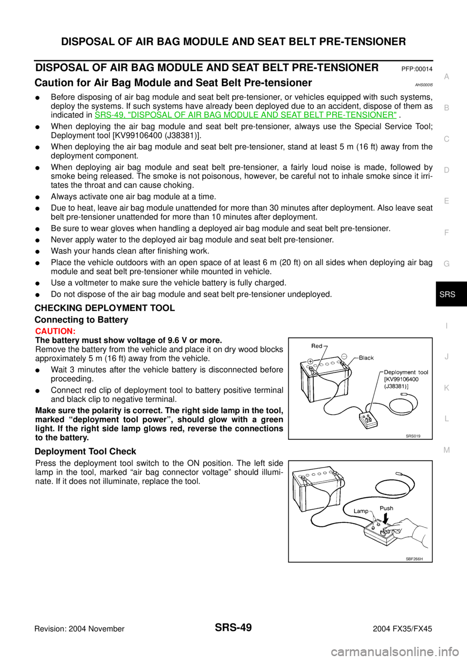
Connecting to Battery
CAUTION:
The battery must show voltage of 9.6 V or more.
Remove the battery from the vehicle and place it on dry wood blocks
approximately 5 m (16 ft) away from the vehicle.
�Wait 3 minutes after the vehicle battery is disconnected before
proceeding.
�Connect red clip of deployment tool to battery positive terminal
and black clip to negative terminal.
Make sure the polarity is correct. The right side lamp in the tool,
marked “deployment tool power”, should glow with a green
light. If the right side lamp glows red, reverse the connections
to the battery.
Deployment Tool Check
Press the deployment tool switch to the ON position. The left side
lamp in the tool, marked “air bag connector voltage” should illumi-
nate. If it does not illuminate, replace the tool.
SRS019
SBF266H
Page 4291 of 4449
SRS-50
DISPOSAL OF AIR BAG MODULE AND SEAT BELT PRE-TENSIONER
Revision: 2004 November 2004 FX35/FX45
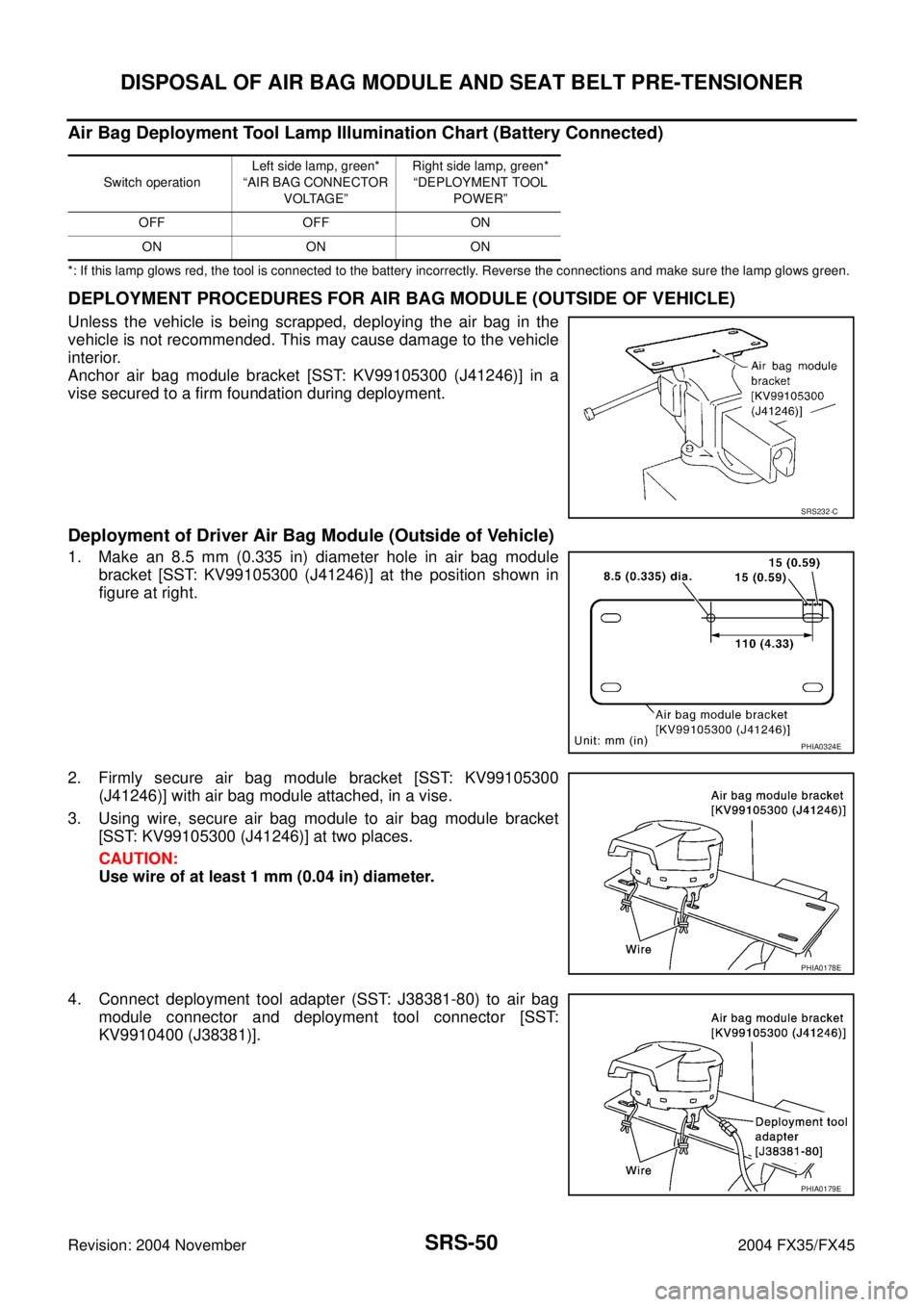
Air Bag Deployment Tool Lamp Illumination Chart (Battery Connected)
*: If this lamp glows red, the tool is connected to the battery incorrectly. Reverse the connections and make sure the lamp glows green.
DEPLOYMENT PROCEDURES FOR AIR BAG MODULE (OUTSIDE OF VEHICLE)
Unless the vehicle is being scrapped, deploying the air bag in the
vehicle is not recommended. This may cause damage to the vehicle
interior.
Anchor air bag module bracket [SST: KV99105300 (J41246)] in a
vise secured to a firm foundation during deployment.
Deployment of Driver Air Bag Module (Outside of Vehicle)
1. Make an 8.5 mm (0.335 in) diameter hole in air bag module
bracket [SST: KV99105300 (J41246)] at the position shown in
figure at right.
2. Firmly secure air bag module bracket [SST: KV99105300
(J41246)] with air bag module attached, in a vise.
3. Using wire, secure air bag module to air bag module bracket
[SST: KV99105300 (J41246)] at two places.
CAUTION:
Use wire of at least 1 mm (0.04 in) diameter.
4. Connect deployment tool adapter (SST: J38381-80) to air bag
module connector and deployment tool connector [SST:
KV9910400 (J38381)].
Switch operationLeft side lamp, green*
“AIR BAG CONNECTOR
VOLTAGE”Right side lamp, green*
“DEPLOYMENT TOOL
POWER”
OFF OFF ON
ON ON ON
SRS232-C
PHIA0324E
PHIA0178E
PHIA0179E
Page 4292 of 4449
DISPOSAL OF AIR BAG MODULE AND SEAT BELT PRE-TENSIONER
SRS-51
C
D
E
F
G
I
J
K
L
MA
B
SRS
Revision: 2004 November 2004 FX35/FX45
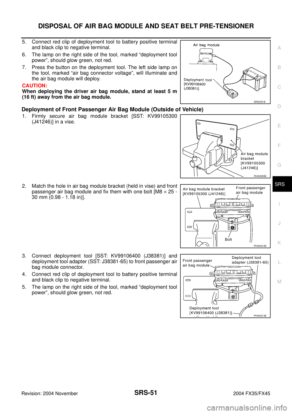
5. Connect red clip of deployment tool to battery positive terminal
and black clip to negative terminal.
6. The lamp on the right side of the tool, marked “deployment tool
power”, should glow green, not red.
7. Press the button on the deployment tool. The left side lamp on
the tool, marked “air bag connector voltage”, will illuminate and
the air bag module will deploy.
CAUTION:
When deploying the driver air bag module, stand at least 5 m
(16 ft) away from the air bag module.
Deployment of Front Passenger Air Bag Module (Outside of Vehicle)
1. Firmly secure air bag module bracket [SST: KV99105300
(J41246)] in a vise.
2. Match the hole in air bag module bracket (held in vise) and front
passenger air bag module and fix them with one bolt [M8 × 25 -
30 mm (0.98 - 1.18 in)].
3. Connect deployment tool [SST: KV99106400 (J38381)] and
deployment tool adapter (SST: J38381-65) to front passenger air
bag module connector.
4. Connect red clip of deployment tool to battery positive terminal
and black clip to negative terminal.
5. The lamp on the right side of the tool, marked “deployment tool
power”, should glow green, not red.
SRS020-B
PHIA0355E
PHIA0312E
PHIA0313E
Page 4294 of 4449
DISPOSAL OF AIR BAG MODULE AND SEAT BELT PRE-TENSIONER
SRS-53
C
D
E
F
G
I
J
K
L
MA
B
SRS
Revision: 2004 November 2004 FX35/FX45
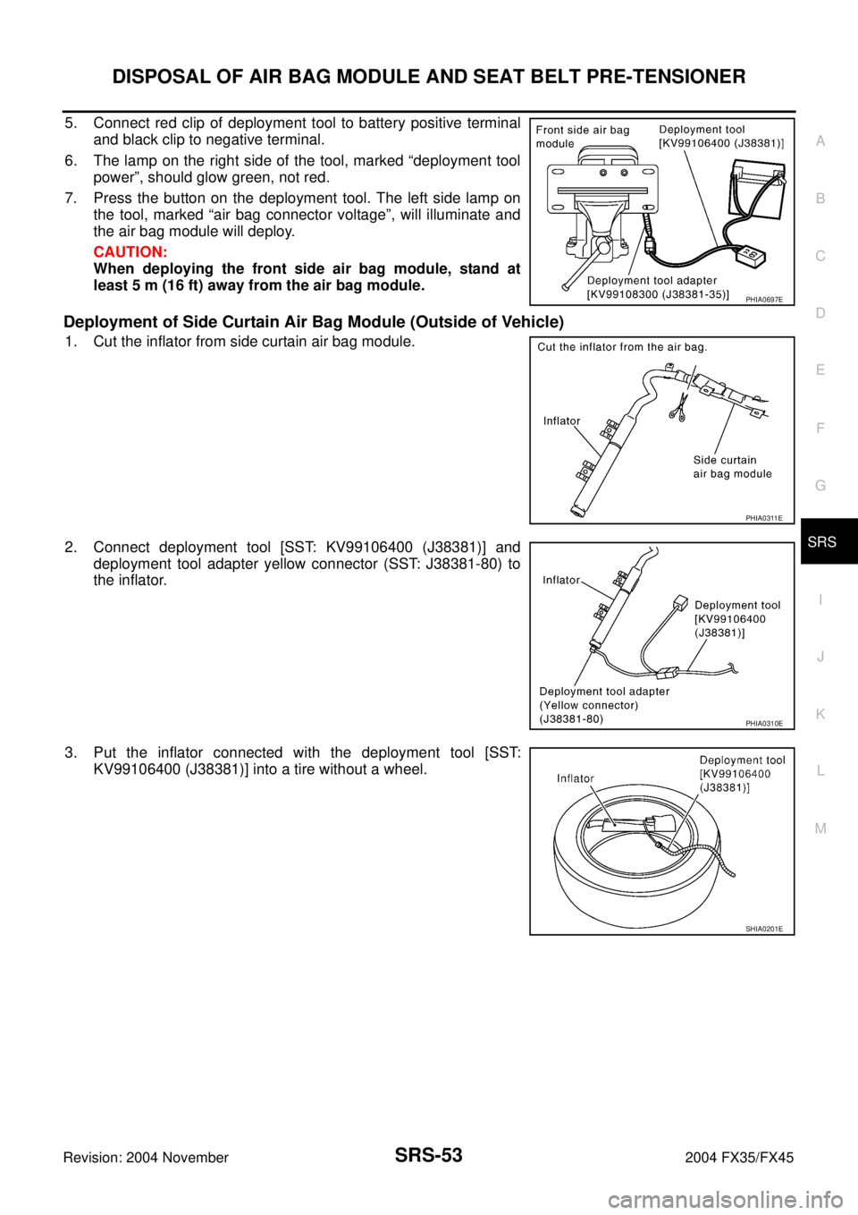
5. Connect red clip of deployment tool to battery positive terminal
and black clip to negative terminal.
6. The lamp on the right side of the tool, marked “deployment tool
power”, should glow green, not red.
7. Press the button on the deployment tool. The left side lamp on
the tool, marked “air bag connector voltage”, will illuminate and
the air bag module will deploy.
CAUTION:
When deploying the front side air bag module, stand at
least 5 m (16 ft) away from the air bag module.
Deployment of Side Curtain Air Bag Module (Outside of Vehicle)
1. Cut the inflator from side curtain air bag module.
2. Connect deployment tool [SST: KV99106400 (J38381)] and
deployment tool adapter yellow connector (SST: J38381-80) to
the inflator.
3. Put the inflator connected with the deployment tool [SST:
KV99106400 (J38381)] into a tire without a wheel.
PHIA0697E
PHIA0311E
PHIA0310E
SHIA0201E
Page 4295 of 4449
SRS-54
DISPOSAL OF AIR BAG MODULE AND SEAT BELT PRE-TENSIONER
Revision: 2004 November 2004 FX35/FX45
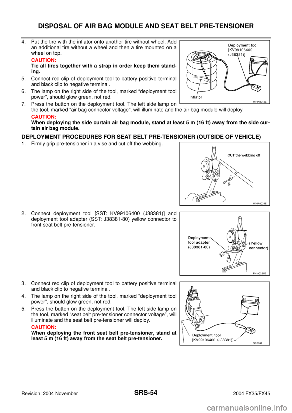
4. Put the tire with the inflator onto another tire without wheel. Add
an additional tire without a wheel and then a tire mounted on a
wheel on top.
CAUTION:
Tie all tires together with a strap in order keep them stand-
ing.
5. Connect red clip of deployment tool to battery positive terminal
and black clip to negative terminal.
6. The lamp on the right side of the tool, marked “deployment tool
power”, should glow green, not red.
7. Press the button on the deployment tool. The left side lamp on
the tool, marked “air bag connector voltage”, will illuminate and the air bag module will deploy.
CAUTION:
When deploying the side curtain air bag module, stand at least 5 m (16 ft) away from the side cur-
tain air bag module.
DEPLOYMENT PROCEDURES FOR SEAT BELT PRE-TENSIONER (OUTSIDE OF VEHICLE)
1. Firmly grip pre-tensioner in a vise and cut off the webbing.
2. Connect deployment tool [SST: KV99106400 (J38381)] and
deployment tool adapter (SST: J38381-80) yellow connector to
front seat belt pre-tensioner.
3. Connect red clip of deployment tool to battery positive terminal
and black clip to negative terminal.
4. The lamp on the right side of the tool, marked “deployment tool
power”, should glow green, not red.
5. Press the button on the deployment tool. The left side lamp on
the tool, marked “seat belt pre-tensioner connector voltage”, will
illuminate and the seat belt pre-tensioner will deploy.
CAUTION:
When deploying the front seat belt pre-tensioner, stand at
least 5 m (16 ft) away from the seat belt pre-tensioner.
WHIA0048E
WHIA0034E
PHIA0221E
SRS242