Page 747 of 4449

AV-156
NAVIGATION SYSTEM
Revision: 2004 November 2004 FX35/FX45
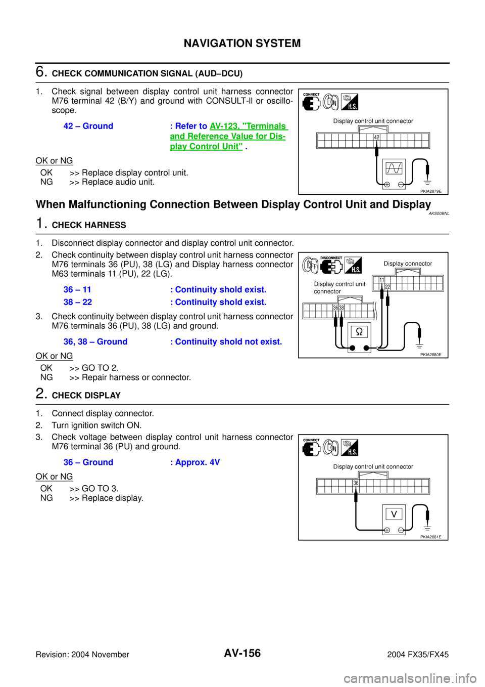
6. CHECK COMMUNICATION SIGNAL (AUD–DCU)
1. Check signal between display control unit harness connector
M76 terminal 42 (B/Y) and ground with CONSULT-ll or oscillo-
scope.
OK or NG
OK >> Replace display control unit.
NG >> Replace audio unit.
When Malfunctioning Connection Between Display Control Unit and Display AKS00BNL
1. CHECK HARNESS
1. Disconnect display connector and display control unit connector.
2. Check continuity between display control unit harness connector
M76 terminals 36 (PU), 38 (LG) and Display harness connector
M63 terminals 11 (PU), 22 (LG).
3. Check continuity between display control unit harness connector
M76 terminals 36 (PU), 38 (LG) and ground.
OK or NG
OK >> GO TO 2.
NG >> Repair harness or connector.
2. CHECK DISPLAY
1. Connect display connector.
2. Turn ignition switch ON.
3. Check voltage between display control unit harness connector
M76 terminal 36 (PU) and ground.
OK or NG
OK >> GO TO 3.
NG >> Replace display.42 – Ground : Refer to AV- 1 2 3 , "
Terminals
and Reference Value for Dis-
play Control Unit" .
PKIA2879E
36 – 11 : Continuity shold exist.
38 – 22 : Continuity shold exist.
36, 38 – Ground : Continuity shold not exist.
PKIA2880E
36 – Ground : Approx. 4V
PKIA2881E
Page 748 of 4449

NAVIGATION SYSTEM
AV-157
C
D
E
F
G
H
I
J
L
MA
B
AV
Revision: 2004 November 2004 FX35/FX45
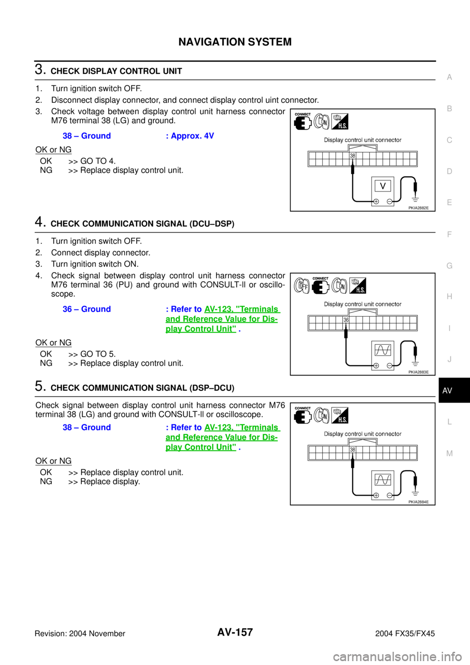
3. CHECK DISPLAY CONTROL UNIT
1. Turn ignition switch OFF.
2. Disconnect display connector, and connect display control uint connector.
3. Check voltage between display control unit harness connector
M76 terminal 38 (LG) and ground.
OK or NG
OK >> GO TO 4.
NG >> Replace display control unit.
4. CHECK COMMUNICATION SIGNAL (DCU–DSP)
1. Turn ignition switch OFF.
2. Connect display connector.
3. Turn ignition switch ON.
4. Check signal between display control unit harness connector
M76 terminal 36 (PU) and ground with CONSULT-ll or oscillo-
scope.
OK or NG
OK >> GO TO 5.
NG >> Replace display control unit.
5. CHECK COMMUNICATION SIGNAL (DSP–DCU)
Check signal between display control unit harness connector M76
terminal 38 (LG) and ground with CONSULT-ll or oscilloscope.
OK or NG
OK >> Replace display control unit.
NG >> Replace display.38 – Ground : Approx. 4V
PKIA2882E
36 – Ground : Refer to AV- 1 2 3 , "Te r m i n a l s
and Reference Value for Dis-
play Control Unit" .
PKIA2883E
38 – Ground : Refer to AV- 1 2 3 , "Te r m i n a l s
and Reference Value for Dis-
play Control Unit" .
PKIA2884E
Page 751 of 4449

AV-160
NAVIGATION SYSTEM
Revision: 2004 November 2004 FX35/FX45
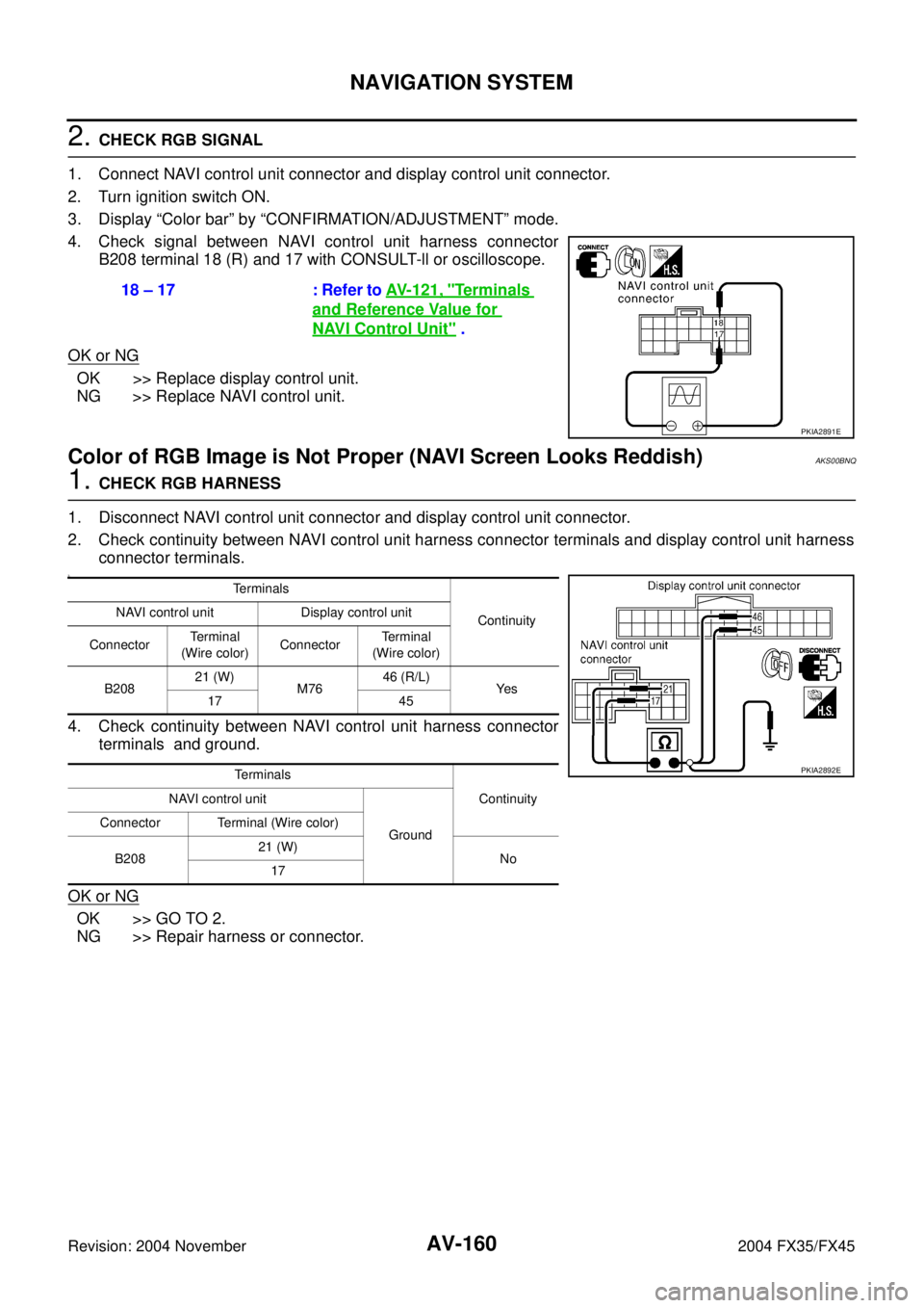
2. CHECK RGB SIGNAL
1. Connect NAVI control unit connector and display control unit connector.
2. Turn ignition switch ON.
3. Display “Color bar” by “CONFIRMATION/ADJUSTMENT” mode.
4. Check signal between NAVI control unit harness connector
B208 terminal 18 (R) and 17 with CONSULT-ll or oscilloscope.
OK or NG
OK >> Replace display control unit.
NG >> Replace NAVI control unit.
Color of RGB Image is Not Proper (NAVI Screen Looks Reddish)AKS00BNQ
1. CHECK RGB HARNESS
1. Disconnect NAVI control unit connector and display control unit connector.
2. Check continuity between NAVI control unit harness connector terminals and display control unit harness
connector terminals.
3.
4. Check continuity between NAVI control unit harness connector
terminals and ground.
OK or NG
OK >> GO TO 2.
NG >> Repair harness or connector.18 – 17 : Refer to AV- 1 2 1 , "
Terminals
and Reference Value for
NAVI Control Unit" .
PKIA2891E
Terminals
Continuity NAVI control unit Display control unit
ConnectorTe r m i n a l
(Wire color)ConnectorTerminal
(Wire color)
B20821 (W)
M7646 (R/L)
Ye s
17 45
Terminals
Continuity NAVI control unit
Ground Connector Terminal (Wire color)
B20821 (W)
No
17
PKIA2892E
Page 752 of 4449

NAVIGATION SYSTEM
AV-161
C
D
E
F
G
H
I
J
L
MA
B
AV
Revision: 2004 November 2004 FX35/FX45
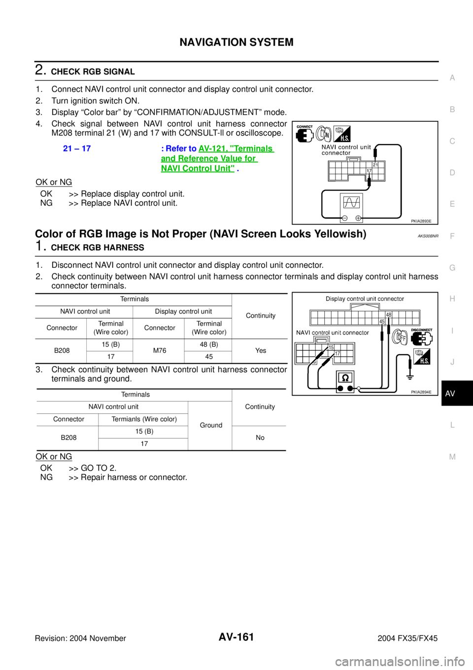
2. CHECK RGB SIGNAL
1. Connect NAVI control unit connector and display control unit connector.
2. Turn ignition switch ON.
3. Display “Color bar” by “CONFIRMATION/ADJUSTMENT” mode.
4. Check signal between NAVI control unit harness connector
M208 terminal 21 (W) and 17 with CONSULT-ll or oscilloscope.
OK or NG
OK >> Replace display control unit.
NG >> Replace NAVI control unit.
Color of RGB Image is Not Proper (NAVI Screen Looks Yellowish)AKS00BNR
1. CHECK RGB HARNESS
1. Disconnect NAVI control unit connector and display control unit connector.
2. Check continuity between NAVI control unit harness connector terminals and display control unit harness
connector terminals.
3. Check continuity between NAVI control unit harness connector
terminals and ground.
OK or NG
OK >> GO TO 2.
NG >> Repair harness or connector.21 – 17 : Refer to AV- 1 2 1 , "
Te r m i n a l s
and Reference Value for
NAVI Control Unit" .
PKIA2893E
Terminals
Continuity NAVI control unit Display control unit
ConnectorTerminal
(Wire color)ConnectorTe r m i n a l
(Wire color)
B20815 (B)
M7648 (B)
Ye s
17 45
Terminals
Continuity NAVI control unit
Ground Connector Termianls (Wire color)
B20815 (B)
No
17
PKIA2894E
Page 753 of 4449

AV-162
NAVIGATION SYSTEM
Revision: 2004 November 2004 FX35/FX45
2. CHECK RGB SIGNAL
1. Connect NAVI control unit connector and display control unit connector.
2. Turn ignition switch ON.
3. Display “Color bar” by “CONFIRMATION/ADJUSTMENT” mode.
4. Check signal between NAVI control unit harness connector
M208 terminal 15 (B) and 17 with CONSULT-ll or oscilloscope.
OK or NG
OK >> Replace display control unit.
NG >> Replace NAVI control unit.
Color of RGB Image is Not Proper (All screens Looks Bluish)AKS00BNS
1. CHECK RGB HARNESS
1. Disconnect display control unit connector and display connector.
2. Check continuity between display control unit harness connector terminals and display harness connector
terminals.
3. Check continuity between display control unit harness connector
terminals and ground.
OK or NG
OK >> GO TO 2.
NG >> Repair harness or connector.15 – 17 : Refer to AV- 1 2 1 , "
Terminals
and Reference Value for NAVI
Control Unit" .
PKIA2895E
Te r m i n a l s
Continuity Display control unit Display
ConnectorTerminal
(Wire color)ConnectorTe r m i n a l
(Wire color)
M7650 (L/R)
M6317 (L/R)
Ye s
47 7
Terminals
Continuity Display control unit
Ground Connector Terminal (Wire color)
M7650 (L/R)
No
47
PKIA2896E
Page 754 of 4449

NAVIGATION SYSTEM
AV-163
C
D
E
F
G
H
I
J
L
MA
B
AV
Revision: 2004 November 2004 FX35/FX45
2. CHECK RGB SIGNAL
1. Connect display control unit connector and display connector.
2. Turn ignition switch ON.
3. Display “Color bar” by “CONFIRMATION/ADJUSTMENT” mode.
4. Check signal between display control unit harness connector
M76 terminals 50 (L/R) and 47 with CONSULT-ll or oscilloscope.
OK or NG
OK >> Replace display.
NG >> Replace display control unit.
Color of RGB Image is Not Proper (All Screens Looks Reddish)AKS00BNT
1. CHECK RGB HARNESS
1. Disconnect display control unit connector and display connector.
2. Check continuity between display control unit harness connector terminals and display control unit har-
ness connector terminals.
3. Check continuity between display control unit harness connector
terminals and ground.
OK or NG
OK >> GO TO 2.
NG >> Repair harness or connector.50 – 47 : Refer to AV- 1 2 3 , "
Te r m i n a l s
and Reference Value for Dis-
play Control Unit" .
PKIA2897E
Terminals
Continuity Display control unit Display
ConnectorTerminal
(Wire color)ConnectorTe r m i n a l
(Wire color)
M7652 (L/W)
M636 (L/W)
Ye s
47 7
Terminals
Continuity Display control unit
Ground Connector Terminal
M7652 (L/W)
No
47
PKIA2898E
Page 755 of 4449

AV-164
NAVIGATION SYSTEM
Revision: 2004 November 2004 FX35/FX45
2. CHECK RGB SIGNAL
1. Connect display control unit connector and display connector.
2. Turn ignition switch ON.
3. Display “Color bar” by “CONFIRMATION/ADJUSTMENT” mode.
4. Check signal between display control unit harness connector
M76 terminal 52 (L/W) and 47 with CONSULT-ll or oscilloscope.
OK or NG
OK >> Replace display.
NG >> Replace display control unit.
Color of RGB Image is Not Proper (All Screens Looks Yellowish)AKS00BNU
1. CHECK RGB HARNESS
1. Disconnect display control unit connector and display connector.
2. Check continuity between display control unit harness connector terminals and display harness connector
terminals.
3. Check continuity between display control unit harness connector
terminals and ground.
OK or NG
OK >> GO TO 2.
NG >> Repair harness or connector.52 – 47 : Refer to AV- 1 2 3 , "
Terminals
and Reference Value for Dis-
play Control Unit" .
PKIA2899E
Terminals
Continuity Display control unit Display
ConnectorTerminal
(Wire color)ConnectorTerminal
(Wire color)
M7654 (L)
M6318 (L)
Ye s
47 7
Terminals
Continuity Display control unit
Ground Connector Terminal (Wire color)
M7654 (L)
No
47
PKIA2900E
Page 756 of 4449
NAVIGATION SYSTEM
AV-165
C
D
E
F
G
H
I
J
L
MA
B
AV
Revision: 2004 November 2004 FX35/FX45
2. CHECK RGB SIGNAL
1. Connect display control unit connector and display connector.
2. Turn ignition switch ON.
3. Display “Color bar” by “CONFIRMATION/ADJUSTMENT” mode.
4. Check signal between display contorl unit harness connector
M76 terminal 54 (L) and 47with CONSULT-ll or oscilloscope.
OK or NG
OK >> Replace display.
NG >> Replace display control unit.54 – 47 : Refer to AV- 1 2 3 , "
Te r m i n a l s
and Reference Value for Dis-
play Control Unit" .
PKIA2901E