Page 3823 of 4449

MA-36
CHASSIS AND BODY MAINTENANCE
Revision: 2004 November 2004 FX35/FX45
Checking Power Steering Fluid and LinesALS000FV
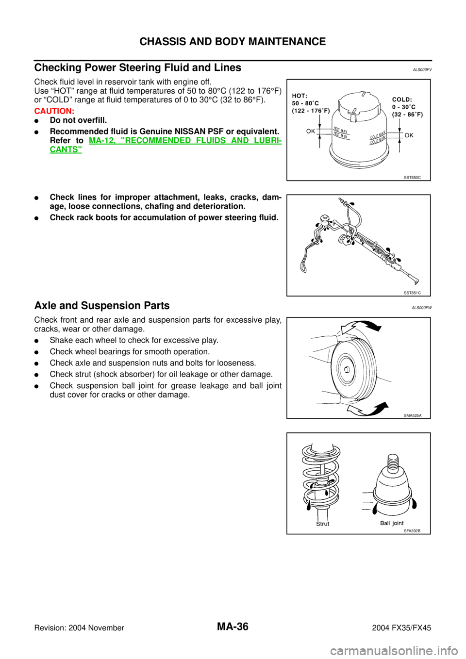
Check fluid level in reservoir tank with engine off.
Use “HOT” range at fluid temperatures of 50 to 80°C (122 to 176°F)
or “COLD” range at fluid temperatures of 0 to 30°C (32 to 86°F).
CAUTION:
�Do not overfill.
�Recommended fluid is Genuine NISSAN PSF or equivalent.
Refer to MA-12, "
RECOMMENDED FLUIDS AND LUBRI-
CANTS"
�Check lines for improper attachment, leaks, cracks, dam-
age, loose connections, chafing and deterioration.
�Check rack boots for accumulation of power steering fluid.
Axle and Suspension PartsALS000FW
Check front and rear axle and suspension parts for excessive play,
cracks, wear or other damage.
�Shake each wheel to check for excessive play.
�Check wheel bearings for smooth operation.
�Check axle and suspension nuts and bolts for looseness.
�Check strut (shock absorber) for oil leakage or other damage.
�Check suspension ball joint for grease leakage and ball joint
dust cover for cracks or other damage.
SST850C
SST851C
SMA525A
SFA392B
Page 3826 of 4449

SERVICE DATA AND SPECIFICATIONS (SDS)
MA-39
C
D
E
F
G
H
I
J
K
MA
B
MA
Revision: 2004 November 2004 FX35/FX45
SERVICE DATA AND SPECIFICATIONS (SDS)PFP:00030
Standard and LimitALS000G0
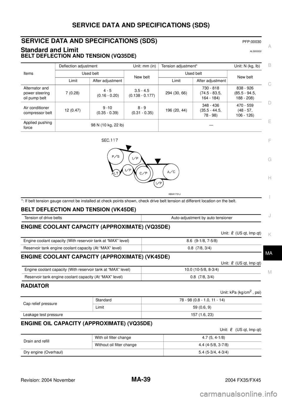
BELT DEFLECTION AND TENSION (VQ35DE)
*: If belt tension gauge cannot be installed at check points shown, check drive belt tension at different location on the belt.
BELT DEFLECTION AND TENSION (VK45DE)
ENGINE COOLANT CAPACITY (APPROXIMATE) (VQ35DE)
Unit: (US qt, lmp qt)
ENGINE COOLANT CAPACITY (APPROXIMATE) (VK45DE)
Unit: (US qt, lmp qt)
RADIATOR
Unit: kPa (kg/cm2 , psi)
ENGINE OIL CAPACITY (APPROXIMATE) (VQ35DE)
Unit: (US qt, lmp qt) ItemsDeflection adjustment Unit: mm (in) Tension adjustment* Unit: N (kg, lb)
Used belt
New beltUsed belt
New belt
Limit After adjustment Limit After adjustment
Alternator and
power steering
oil pump belt 7 (0.28)4 - 5
(0.16 - 0.20)3.5 - 4.5
(0.138 - 0.177)294 (30, 66)730 - 818
(74.5 - 83.5,
164 - 184)838 - 926
(85.5 - 94.5,
188 - 208)
Air conditioner
compressor belt 12 (0.47)9 -10
(0.35 - 0.39)8 - 9
(0.31 - 0.35)196 (20, 44)348 - 436
(35.5 - 44.5,
78 - 98)470 - 559
(48 - 57,
106 - 126)
Applied pushing
force98 N (10 kg, 22 lb) —
KBIA1731J
Tension of drive belts Auto-adjustment by auto tensioner
Engine coolant capacity (With reservoir tank at “MAX” level) 8.6 (9-1/8, 7-5/8)
Reservoir tank engine coolant capacity (At “MAX” level) 0.8 (7/8, 3/4)
Engine coolant capacity (With reservoir tank at “MAX” level) 10.0 (10-5/8, 8-3/4)
Reservoir tank engine coolant capacity (At “MAX” level) 0.8 (7/8, 3/4)
Cap relief pressureStandard 78 - 98 (0.8 - 1.0, 11 - 14)
Limit 59 (0.6, 9)
Leakage test pressure157 (1.6, 23)
Drain and refill With oil filter change 4.7 (5, 4-1/8)
Without oil filter change 4.4 (4-5/8, 3-7/8)
Dry engine (Overhaul) 5.4 (5-3/4, 4-3/4)
Page 3829 of 4449

PB-2
PARKING BRAKE SYSTEM
Revision: 2004 November 2004 FX35/FX45
PARKING BRAKE SYSTEMPFP:36010
On-Vehicle ServiceAFS001TJ
PEDAL STROKE
�When parking brake pedal is operated with a force of 200 N (20.4 kg, 44.9 lb), make sure the stroke is
within the specified number of notches. (Check it by listening and counting the ratchet clicks.)
INSPECT COMPONENTS
�Make sure the components are attached properly (check for looseness, backlash, etc.).
�Check parking brake pedal assembly for bend, damage and cracks, and replace if necessary.
�Check cable for wear and damage, and replace if necessary.
�Check parking brake warning lamp switch for malfunction, and replace if necessary.
ADJUSTMENT
�To perform adjustment operations, remove tire from the vehicle with power tool.
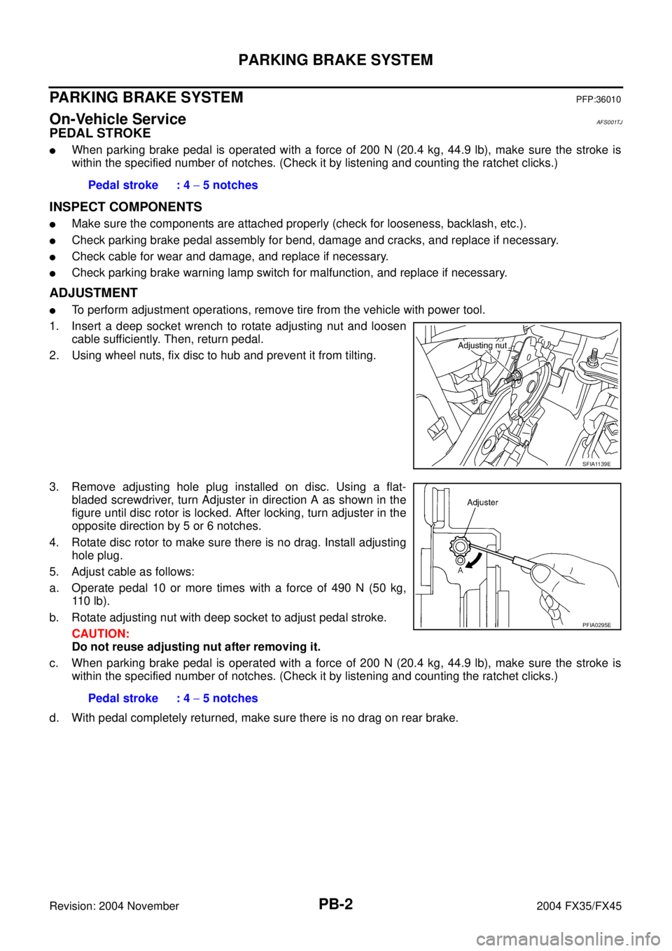
1. Insert a deep socket wrench to rotate adjusting nut and loosen
cable sufficiently. Then, return pedal.
2. Using wheel nuts, fix disc to hub and prevent it from tilting.
3. Remove adjusting hole plug installed on disc. Using a flat-
bladed screwdriver, turn Adjuster in direction A as shown in the
figure until disc rotor is locked. After locking, turn adjuster in the
opposite direction by 5 or 6 notches.
4. Rotate disc rotor to make sure there is no drag. Install adjusting
hole plug.
5. Adjust cable as follows:
a. Operate pedal 10 or more times with a force of 490 N (50 kg,
11 0 l b ) .
b. Rotate adjusting nut with deep socket to adjust pedal stroke.
CAUTION:
Do not reuse adjusting nut after removing it.
c. When parking brake pedal is operated with a force of 200 N (20.4 kg, 44.9 lb), make sure the stroke is
within the specified number of notches. (Check it by listening and counting the ratchet clicks.)
d. With pedal completely returned, make sure there is no drag on rear brake.Pedal stroke : 4 − 5 notches
SFIA1139E
Pedal stroke : 4 − 5 notches
PFIA0295E
Page 3836 of 4449

PG-1
POWER SUPPLY, GROUND & CIRCUIT ELEMENTS
K ELECTRICAL
CONTENTS
C
D
E
F
G
H
I
J
L
M
SECTION PG
A
B
PG
Revision: 2004 November 2004 FX35/FX45
POWER SUPPLY, GROUND & CIRCUIT ELEMENTS
POWER SUPPLY ROUTING CIRCUIT ...................... 3
Schematic ................................................................ 3
Wiring Diagram - POWER - ..................................... 4
BATTERY POWER SUPPLY - IGNITION SW. IN
ANY POSITION ..................................................... 4
ACCESSORY POWER SUPPLY - IGNITION SW.
IN “ACC” OR “ON” .............................................. 10
IGNITION POWER SUPPLY - IGNITION SW. IN
“ON” AND/OR “START” ....................................... 12
Fuse ....................................................................... 17
Fusible Link ............................................................ 17
Circuit Breaker ....................................................... 17
IPDM E/R (INTELLIGENT POWER DISTRIBUTION
MODULE ENGINE ROOM) ...................................... 18
System Description ................................................ 18
SYSTEMS CONTROLLED BY IPDM E/R ........... 18
CAN COMMUNICATION LINE CONTROL ......... 18
IPDM E/R STATUS CONTROL ........................... 19
CAN Communication System Description .............. 19
CAN Communication Unit ...................................... 19
Function of Detecting Ignition Relay Malfunction ... 19
CONSULT-II ........................................................... 20
CONSULT-II INSPECTION PROCEDURE ......... 20
SELF-DIAG RESULTS ........................................ 21
DATA MONITOR ................................................. 22
ACTIVE TEST ..................................................... 22
Auto Active Test ..................................................... 24
DESCRIPTION .................................................... 24
OPERATION PROCEDURE ............................... 24
INSPECTION IN AUTO ACTIVE TEST MODE ... 24
Schematic .............................................................. 26
IPDM E/R Terminal Arrangement ........................... 27
IPDM E/R Power/Ground Circuit Inspection .......... 28
Inspection With CONSULT-II (Self-Diagnosis) ....... 29
Removal and Installation of IPDM E/R ................... 30
REMOVAL ........................................................... 30
INSTALLATION ................................................... 30GROUND ................................................................... 31
Ground Distribution ................................................. 31
MAIN HARNESS ................................................. 31
ENGINE ROOM HARNESS ................................ 34
ENGINE HARNESS/VK ENGINE MODELS ........ 37
ENGINE HARNESS/VQ ENGINE MODELS ....... 38
ENGINE CONTROL HARNESS/VK ENGINE
MODELS ............................................................. 39
ENGINE CONTROL HARNESS/VQ ENGINE
MODELS ............................................................. 40
BODY HARNESS ................................................ 41
BODY NO.2 HARNESS ...................................... 44
ROOM LAMP HARNESS .................................... 45
HARNESS ................................................................. 46
Harness Layout ...................................................... 46
HOW TO READ HARNESS LAYOUT ................. 46
OUTLINE ............................................................. 47
MAIN HARNESS ................................................. 48
ENGINE ROOM HARNESS ................................ 51
ENGINE HARNESS/VK ENGINE MODELS ........ 54
ENGINE HARNESS/VQ ENGINE MODELS ....... 55
ENGINE CONTROL HARNESS/VK ENGINE
MODELS ............................................................. 56
ENGINE CONTROL HARNESS/VQ ENGINE
MODELS ............................................................. 58
BODY HARNESS ................................................ 60
BODY NO.2 HARNESS ...................................... 62
ROOM LAMP HARNESS .................................... 63
FRONT DOOR HARNESS .................................. 64
REAR DOOR HARNESS .................................... 65
BACK DOOR HARNESS .................................... 66
Wiring Diagram Codes (Cell Codes) ...................... 67
ELECTRICAL UNITS LOCATION ............................ 70
Electrical Units Location ......................................... 70
ENGINE COMPARTMENT .................................. 70
PASSENGER COMPARTMENT ......................... 71
LUGGAGE COMPARTMENT .............................. 73
HARNESS CONNECTOR ......................................... 74
Description .............................................................. 74
HERNESS CONNECTOR (TAB-LOCKING
Page 3838 of 4449
POWER SUPPLY ROUTING CIRCUIT
PG-3
C
D
E
F
G
H
I
J
L
MA
B
PG
Revision: 2004 November 2004 FX35/FX45
POWER SUPPLY ROUTING CIRCUITPFP:24110
SchematicAKS007VU
TKWM1305E
Page 3839 of 4449
PG-4
POWER SUPPLY ROUTING CIRCUIT
Revision: 2004 November 2004 FX35/FX45
Wiring Diagram - POWER -AKS007VV
BATTERY POWER SUPPLY - IGNITION SW. IN ANY POSITION
TKWM0708E
Page 3840 of 4449
POWER SUPPLY ROUTING CIRCUIT
PG-5
C
D
E
F
G
H
I
J
L
MA
B
PG
Revision: 2004 November 2004 FX35/FX45
TKWM1306E
Page 3841 of 4449
PG-6
POWER SUPPLY ROUTING CIRCUIT
Revision: 2004 November 2004 FX35/FX45
TKWM1307E