Page 2960 of 4449
CYLINDER HEAD
EM-235
[VK45DE]
C
D
E
F
G
H
I
J
K
L
MA
EM
Revision: 2004 November 2004 FX35/FX45
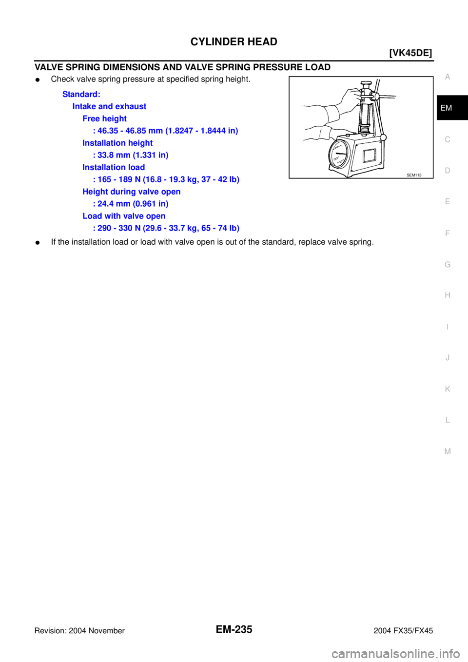
VALVE SPRING DIMENSIONS AND VALVE SPRING PRESSURE LOAD
�Check valve spring pressure at specified spring height.
�If the installation load or load with valve open is out of the standard, replace valve spring.Standard:
Intake and exhaust
Free height
: 46.35 - 46.85 mm (1.8247 - 1.8444 in)
Installation height
: 33.8 mm (1.331 in)
Installation load
: 165 - 189 N (16.8 - 19.3 kg, 37 - 42 lb)
Height during valve open
: 24.4 mm (0.961 in)
Load with valve open
: 290 - 330 N (29.6 - 33.7 kg, 65 - 74 lb)
SEM113
Page 2990 of 4449
![INFINITI FX35 2004 Service Manual CYLINDER BLOCK
EM-265
[VK45DE]
C
D
E
F
G
H
I
J
K
L
MA
EM
Revision: 2004 November 2004 FX35/FX45
CRUSH HEIGHT OF MAIN BEARING
�When main bearing cap is removed after being tightened to the
specified to](/manual-img/42/57021/w960_57021-2989.png "INFINITI FX35 2004 Service Manual CYLINDER BLOCK
EM-265
[VK45DE]
C
D
E
F
G
H
I
J
K
L
MA
EM
Revision: 2004 November 2004 FX35/FX45
CRUSH HEIGHT OF MAIN BEARING
�When main bearing cap is removed after being tightened to the
specified to")
CYLINDER BLOCK
EM-265
[VK45DE]
C
D
E
F
G
H
I
J
K
L
MA
EM
Revision: 2004 November 2004 FX35/FX45
CRUSH HEIGHT OF MAIN BEARING
�When main bearing cap is removed after being tightened to the
specified torque with main bearings installed, the tip end of bear-
ing must protrude. Refer to EM-244, "
ASSEMBLY" for the
tightening procedure.
�If the standard is not met, replace main bearings.
CRUSH HEIGHT OF CONNECTING ROD BEARING
�When connecting rod bearing cap is removed after being tight-
ened to the specified torque with connecting rod bearings
installed, the tip end of bearing must protrude. Refer to EM-244,
"ASSEMBLY" for the tightening procedure.
�If the standard is not met, replace connecting rod bearings.
DRIVE PLATE
�Check drive plate and signal plate for deformation or cracks.
CAUTION:
�Do not disassemble drive plate.
�Do not place drive plate with signal plate facing down.
�When handling signal plate, take care not to damage or
scratch it.
�Handle signal plate in a manner that prevents it from
becoming magnetized.
�If anything is found, replace drive plate.Standard : There must be crush height.
SEM502G
Standard : There must be crush height.
PBIC1646E
PBIC2367E
Page 2992 of 4449
![INFINITI FX35 2004 Service Manual SERVICE DATA AND SPECIFICATIONS (SDS)
EM-267
[VK45DE]
C
D
E
F
G
H
I
J
K
L
MA
EM
Revision: 2004 November 2004 FX35/FX45
SPARK PLUG
CAMSHAFT AND CAMSHAFT BEARING
Unit: mm (in)
*: Total indicator reading](/manual-img/42/57021/w960_57021-2991.png "INFINITI FX35 2004 Service Manual SERVICE DATA AND SPECIFICATIONS (SDS)
EM-267
[VK45DE]
C
D
E
F
G
H
I
J
K
L
MA
EM
Revision: 2004 November 2004 FX35/FX45
SPARK PLUG
CAMSHAFT AND CAMSHAFT BEARING
Unit: mm (in)
*: Total indicator reading")
SERVICE DATA AND SPECIFICATIONS (SDS)
EM-267
[VK45DE]
C
D
E
F
G
H
I
J
K
L
MA
EM
Revision: 2004 November 2004 FX35/FX45
SPARK PLUG
CAMSHAFT AND CAMSHAFT BEARING
Unit: mm (in)
*: Total indicator reading
Valve Lifter
Unit: mm (in)
Valve Clearance
Unit: mm (in)
*: Approximately 20°C (68°F) MakeNGK
Standard typePLFR5A-11
Hot typePLFR4A-11
Cold typePLFR6A-11
Gap (nominal)1.1 mm (0.043 in)
ItemsStandard Limit
Camshaft journal clearanceNo. 1 0.045 - 0.083 (0.0018 - 0.0033) —
No. 2, 3, 4, 5 0.030 - 0.068 (0.0012 - 0.0027) —
Camshaft journal diameterNo. 1 25.938 - 25.955 (1.0212 - 1.0218) —
No. 2, 3, 4, 5 25.953 - 25.970 (1.0218 - 1.0224) —
Camshaft bracket inner diameter 26.000 - 26.021 (1.0236 - 1.0244) —
Camshaft end play 0.115 - 0.188 (0.0045 - 0.0074) —
Cam height “A”Intake 44.865 - 45.055 (1.7663 - 1.7738) 0.2 (0.008)
Exhaust 43.925 - 44.115 (1.7293 - 1.7368) 0.2 (0.008)
Camshaft runout [TIR*] — 0.02 (0.0008)
Camshaft sprocket runout [TIR*] — 0.15 (0.059)
SEM671
ItemsStandard
Valve lifter outer diameter 33.965 - 33.975 (1.3372 - 1.3776)
Valve lifter hole diameter 34.000 - 34.016 (1.3386 - 1.3392)
Valve lifter clearance 0.025 - 0.051 (0.0010 - 0.0020)
Items Hot Cold* (reference data)
Intake 0.304 - 0.416 (0.012 - 0.016) 0.26 - 0.34 (0.010 - 0.013)
Exhaust 0.308 - 0.432 (0.012 - 0.017) 0.29 - 0.37 (0.011 - 0.015)
Page 2996 of 4449
SERVICE DATA AND SPECIFICATIONS (SDS)
EM-271
[VK45DE]
C
D
E
F
G
H
I
J
K
L
MA
EM
Revision: 2004 November 2004 FX35/FX45
Valve Seat
Unit: mm (in)
Valve Spring
Items Standard Service
Cylinder head seat recess diameter “D”Intake 37.000 - 37.016 (1.4567 - 1.4573) 37.500 - 37.516 (1.4764 - 1.4770)
Exhaust 32.200 - 32.216 (1.2677 - 1.2683) 32.700 - 32.716 (1.2874 - 1.2880)
Valve seat interference fitIntake 0.081 - 0.113 (0.0032 - 0.0044)
Exhaust 0.064 - 0.096 (0.0025 - 0.0038)
Valve seat outer diameter “d”Intake 37.097 - 37.113 (1.4605 - 1.4611) 37.597 - 37.613 (1.4802 - 1.4808)
Exhaust 32.280 - 32.296 (1.2709 - 1.2715) 32.780 - 32.796 (1.2905 - 1.2912)
PBIC2379E
Free height mm (in) 46.35 - 46.85 (1.8247 - 1.8444)
Pressure N (kg, lb) at height mm (in)Installation 165 - 189 (16.8 - 19.3, 37 - 42) at 33.8 (1.331)
Valve open 290 - 330 (29.6 - 33.7, 65 - 74) at 24.4 (0.961)
Out-of-square mm (in) Limit 2.0 (0.079)
Page 3036 of 4449

FFD-1
FRONT FINAL DRIVE
D DRIVELINE/AXLE
CONTENTS
C
E
F
G
H
I
J
K
L
M
SECTION FFD
A
B
FFD
Revision: 2004 November 2004 FX35/FX45
FRONT FINAL DRIVE
PRECAUTIONS .......................................................... 2
Precautions .............................................................. 2
PREPARATION ........................................................... 3
Special Service Tools ............................................... 3
Commercial Service Tools ........................................ 5
NOISE, VIBRATION AND HARSHNESS (NVH)
TROUBLESHOOTING ................................................ 6
NVH Troubleshooting Chart ..................................... 6
FRONT OIL SEAL ...................................................... 7
Removal and Installation .......................................... 7
REMOVAL ............................................................. 7
INSTALLATION ..................................................... 8
SIDE OIL SEAL .......................................................... 9
Removal and Installation .......................................... 9
REMOVAL ............................................................. 9
INSTALLATION ..................................................... 9
FRONT FINAL DRIVE ASSEMBLY .......................... 10
Removal and Installation (VQ35DE) ...................... 10
REMOVAL ........................................................... 10
INSTALLATION ................................................... 10
Removal and Installation (VK45DE) ........................ 11
REMOVAL ............................................................ 11
INSTALLATION .................................................... 11
Front Final Drive Breather Hose ............................ 12
REMOVAL AND INSTALLATION (VQ35DE) ....... 12
REMOVAL AND INSTALLATION (VK45DE) ....... 13
Components ........................................................... 14
COMPONENTS (VQ35DE) ................................. 14
COMPONENTS (VK45DE) ................................. 16Side Shaft ............................................................... 18
BEARING AND OIL SEAL REPLACEMENT ....... 18
EXTENSION TUBE REPLACEMENT ................. 19
PRE-DISASSEMBLY INSPECTION .................... 19
DISASSEMBLY AND ASSEMBLY ...................... 21
Differential Case Assembly .................................... 24
Installation Drive Pinion Assembly ......................... 27
DIFFERENTIAL CASE INSTALLATION .............. 28
TOOTH CONTACT INSPECTION ....................... 30
TOOTH CONTACT PATTERN AND HEIGHT
ADJUSTING WASHER SELECTION .................. 31
TOOTH CONTACT ADJUSTMENT ..................... 31
TOTAL PRELOAD INSPECTION ........................ 33
DRIVE PINION PRELOAD ADJUSTMENT ......... 33
After Inspection ....................................................... 35
Carrier Cover Installation ........................................ 36
SERVICE DATA AND SPECIFICATIONS (SDS) ...... 37
General Specifications ............................................ 37
Drive Gear Runout .................................................. 37
Side Gear Adjustment ............................................ 37
Available Side Gear Thrust Washers ...................... 37
SIDE BEARING PRELOAD ADJUSTING SHIMS ... 37
Drive Pinion Height Adjustment .............................. 38
AVAILABLE PINION HEIGHT ADJUSTING
WASHERS .......................................................... 38
Drive Pinion Preload Adjustment ............................ 38
AVAILABLE PINION HEIGHT ADJUSTING
WASHERS .......................................................... 38
Total Preload Adjustment ........................................ 38
Page 3050 of 4449
FRONT FINAL DRIVE ASSEMBLY
FFD-15
C
E
F
G
H
I
J
K
L
MA
B
FFD
Revision: 2004 November 2004 FX35/FX45
1. Washer 2. Carrier cover 3. Gear oil defence
4. Breather joint 5. Dowel pin 6. Drive pinion height adjusting washer
7. Drive pinion 8. Drive gear 9. Side bearing adjusting washer
10. Differential case 11. Side bearing 12. O-ring
13. Front oil seal 14. Side retainer 15. Side bearing adjusting shim
16. Air breather hose 17. Bushing 18. Breather tube
19. Companion flange 20. Drive pinion bearing 21. Drive pinion bearing adjusting
washer
22. Drive pinion adjusting washer 23. Extension tube retainer 24. Dust sealed
25. Side shaft 26. Extension tube 27. Carrier case
28. Side gear thrust washer 29. Lock pin 30. Pinion mate gear
31. Pinion mate thrust washer 32. Pinion mate shaft 33. Circlip
34. Side gear 35. Filler plug 36. Drain plug
37. Drive pinion lock nut 38. Side oil seal 39. Side shaft oil seal
40. Bearing
Page 3051 of 4449
FFD-16
FRONT FINAL DRIVE ASSEMBLY
Revision: 2004 November 2004 FX35/FX45
COMPONENTS (VK45DE)
1. Washer 2. Carrier cover 3. Gear oil defence
4. Breather joint 5. Dowel pin 6. Drive pinion height adjusting washer
SDIA1644E
Page 3062 of 4449

FRONT FINAL DRIVE ASSEMBLY
FFD-27
C
E
F
G
H
I
J
K
L
MA
B
FFD
Revision: 2004 November 2004 FX35/FX45
Installation Drive Pinion AssemblyADS000NP
1. Press-fit the drive pinion bearing outer race into the carrier case
with tool.
CAUTION:
First lightly tap outer race using a hammer, place the carrier
case and outer race parallel. Then press-fit outer race with
press.
2. Temporarily install the removed drive pinion height adjusting
washer or same thickness washer to drive pinion.
3. If the hypoid gear set has been replaced, select the adjusting
washer.
Temporarily install washer to the drive pinion.
CAUTION:
Select the washer form the drive pinion height adjusting washer selecting table. Refer to FFD-38,
"AVAILABLE PINION HEIGHT ADJUSTING WASHERS" .
4. Press-fit the drive pinion bearing onto the drive pinion using drift
and press.
NOTE:
Note the direction of washer.
5. Install the drive pinion and drive pinion bearing as follows:
a. Apply gear oil to the bearing portion.
b. Install the drive pinion and drive pinion bearing (front side) into
the carrier case.Tool number : KV31103000 ( – )
SDIA1679E
SDIA1666E
Washer selection equation:
T = T0 + (t1 - t2)
T = Correct washer thickness
T0 = Removed washer thickness
t1 = Old drive pinion head letter
(machined tolerance 1/100 mm x 100)
t2 = New drive pinion head letter
(machined tolerance 1/100 mm x 100)
Example:
In case the T0 = 3.21, t1 = +2, t2 = -1
T = 3.21 + ((2 x 0.01) - (-1 x 0.01)) = 3.24
Tool number : ST30032000 ( – )
SDIA0249J
SDIA1668E
![INFINITI FX35 2004 Service Manual SERVICE DATA AND SPECIFICATIONS (SDS)
EM-271
[VK45DE]
C
D
E
F
G
H
I
J
K
L
MA
EM
Revision: 2004 November 2004 FX35/FX45
Valve Seat
Unit: mm (in)
Valve Spring
Items Standard Service
Cylinder head seat r](/manual-img/42/57021/w960_57021-2995.png "INFINITI FX35 2004 Service Manual SERVICE DATA AND SPECIFICATIONS (SDS)
EM-271
[VK45DE]
C
D
E
F
G
H
I
J
K
L
MA
EM
Revision: 2004 November 2004 FX35/FX45
Valve Seat
Unit: mm (in)
Valve Spring
Items Standard Service
Cylinder head seat r")


1. Washer 2. Carrier cover 3. Gear oil defence
4. Breather joint 5. Dowel pin 6. Drive pinion height adjust")