Page 2811 of 4449
![INFINITI FX35 2004 Service Manual EM-86
[VQ35DE]
CAMSHAFT
Revision: 2004 November 2004 FX35/FX45
2. Measure camshaft sprocket runout with dial indicator. (Total indi-
cator reading)
�If it exceeds the limit, replace camshaft sprocket.](/manual-img/42/57021/w960_57021-2810.png "INFINITI FX35 2004 Service Manual EM-86
[VQ35DE]
CAMSHAFT
Revision: 2004 November 2004 FX35/FX45
2. Measure camshaft sprocket runout with dial indicator. (Total indi-
cator reading)
�If it exceeds the limit, replace camshaft sprocket.")
EM-86
[VQ35DE]
CAMSHAFT
Revision: 2004 November 2004 FX35/FX45
2. Measure camshaft sprocket runout with dial indicator. (Total indi-
cator reading)
�If it exceeds the limit, replace camshaft sprocket.
Valve Lifter
Check if surface of valve lifter has any wear or cracks.
�If anything above is found, replace valve lifter.
Valve Lifter Clearance
Outer Diameter of Valve Lifter
Measure outer diameter at 1/2 height of valve lifter with micrometer
since valve lifter is in barrel shape.
Valve Lifter Hole Diameter
Using inside micrometer, measure diameter of valve lifter hole of cyl-
inder head.
Calculation of Valve Lifter Clearance
(Valve lifter clearance) = (hole diameter of valve lifter) – (outer diameter of valve lifter).
If it exceeds the standard, referring to each standard of valve lifter outer diameter and valve lifter hole diame-
ter, replace either or both valve lifter and cylinder head.Limit : 0.15 mm (0.0059 in)
PBIC0930E
KBIA0182E
Valve lifter outer diameter (Intake and exhaust)
: 33.977 - 33.987 mm (1.3377 - 1.3381 in)
JEM798G
Standard (Intake and exhaust)
: 34.000 - 34.016 mm (1.3386 - 1.3392 in)
SEM867E
Standard (Intake and exhaust)
: 0.013 - 0.039 mm (0.0005 - 0.0015 in)
Page 2819 of 4449
![INFINITI FX35 2004 Service Manual EM-94
[VQ35DE]
OIL SEAL
Revision: 2004 November 2004 FX35/FX45
OIL SEALPFP:00100
Removal and Installation of Valve Oil SealABS004X4
REMOVAL
1. Remove camshaft relating to valve oil seal to be removed.](/manual-img/42/57021/w960_57021-2818.png "INFINITI FX35 2004 Service Manual EM-94
[VQ35DE]
OIL SEAL
Revision: 2004 November 2004 FX35/FX45
OIL SEALPFP:00100
Removal and Installation of Valve Oil SealABS004X4
REMOVAL
1. Remove camshaft relating to valve oil seal to be removed.")
EM-94
[VQ35DE]
OIL SEAL
Revision: 2004 November 2004 FX35/FX45
OIL SEALPFP:00100
Removal and Installation of Valve Oil SealABS004X4
REMOVAL
1. Remove camshaft relating to valve oil seal to be removed. Refer to EM-82, "CAMSHAFT" .
2. Remove valve lifters. Refer to EM-82, "
CAMSHAFT" .
3. Turn crankshaft until the cylinder requiring new oil seals is at TDC. This will prevent valve from dropping
into cylinder.
4. Using valve spring compressor, attachment and adapter (SST),
remove valve collet with magnet hand. Then remove valve
spring and valve spring seat.
5. Remove valve oil seal using valve oil seal puller (SST).
INSTALLATION
1. Apply engine oil on new valve oil seal joint and seal lip.
2. Using valve oil seal drift (SST), press fit valve seal to height “H”
shown in the figure.
NOTE:
Dimension “H”: Height measured before valve spring seat instal-
lation
3. Perform steps in the reverse order of removal for the following operations.
PBIC1803E
PBIC0884E
Intake and exhaust : 14.3 - 14.9 mm (0.563 - 0.587 in)
PBIC0802E
Page 2821 of 4449
![INFINITI FX35 2004 Service Manual EM-96
[VQ35DE]
OIL SEAL
Revision: 2004 November 2004 FX35/FX45
INSTALLATION
1. Apply engine oil on new front oil seal.
2. Using a suitable drift, press fit until the height of front oil seal is
level](/manual-img/42/57021/w960_57021-2820.png "INFINITI FX35 2004 Service Manual EM-96
[VQ35DE]
OIL SEAL
Revision: 2004 November 2004 FX35/FX45
INSTALLATION
1. Apply engine oil on new front oil seal.
2. Using a suitable drift, press fit until the height of front oil seal is
level")
EM-96
[VQ35DE]
OIL SEAL
Revision: 2004 November 2004 FX35/FX45
INSTALLATION
1. Apply engine oil on new front oil seal.
2. Using a suitable drift, press fit until the height of front oil seal is
level with the mounting surface.
�Suitable drift: outer diameter 59 mm (2.32 in), inner diameter
49 mm (1.93 in).
CAUTION:
Press fit straight and avoid causing burrs or tilting oil
seal.
3. Perform steps in the reverse order of removal for the following operations.
Removal and Installation of Rear Oil SealABS004X6
REMOVAL
1. Remove oil pan (upper). Refer to EM-30, "OIL PAN AND OIL STRAINER" .
2. Remove transmission assembly. Refer to AT- 2 6 6 , "
TRANSMISSION ASSEMBLY" .
3. Remove drive plate with power tool. Fix crankshaft with a ring gear stopper [SST: KV1011770 (J-44716)],
and remove mounting bolts.
�Loosen mounting bolts in diagonal order.
CAUTION:
�Do not disassemble drive plate.
�Never place drive plate with signal plate facing down.
�When handling signal plate, take care not to damage or
scratch it.
�Handle signal plate in a manner that prevents it from
becoming magnetized.
4. Use a seal cutter (SST) to cut away liquid gasket and remove
rear oil seal retainer.
CAUTION:
Be careful not to damage mounting surface.
NOTE:
Rear oil seal and retainer form a single part and are handled as
an assembly.
INSTALLATION
1. Remove old liquid gasket on mating surface of cylinder block and oil pan using scraper.
SEM715A
SEM760G
SEM830E
Page 2828 of 4449
![INFINITI FX35 2004 Service Manual CYLINDER HEAD
EM-103
[VQ35DE]
C
D
E
F
G
H
I
J
K
L
MA
EM
Revision: 2004 November 2004 FX35/FX45
DISASSEMBLY
1. Remove spark plug with spark plug wrench (commercial service tool).
2. Remove valve lifter](/manual-img/42/57021/w960_57021-2827.png "INFINITI FX35 2004 Service Manual CYLINDER HEAD
EM-103
[VQ35DE]
C
D
E
F
G
H
I
J
K
L
MA
EM
Revision: 2004 November 2004 FX35/FX45
DISASSEMBLY
1. Remove spark plug with spark plug wrench (commercial service tool).
2. Remove valve lifter")
CYLINDER HEAD
EM-103
[VQ35DE]
C
D
E
F
G
H
I
J
K
L
MA
EM
Revision: 2004 November 2004 FX35/FX45
DISASSEMBLY
1. Remove spark plug with spark plug wrench (commercial service tool).
2. Remove valve lifter.
�Mark position on valve lifter for assembly.
3. Remove valve collet.
�Compress valve spring with valve spring compressor, attach-
ment and adapter (SST). Remove valve collet with magnet
hand.
CAUTION:
When working, take care not to damage valve lifter holes.
4. Remove valve spring retainer and valve spring.
5. Push valve stem to combustion chamber side, and remove
valve.
�Inspect valve guide clearance before removal. Refer to EM-
105, "VALVE GUIDE CLEARANCE" .
�Mark position on valve for assembly.
6. Remove valve oil seals using valve oil seal puller (SST).
7. Remove valve spring seat.
8. If valve seat must be replaced, refer to EM-107, "
VALVE SEAT CONTACT" .
9. If valve guide must be replaced, refer to EM-105, "
VALVE GUIDE CLEARANCE" .
10. Remove spark plug tube, as necessary.
�Using a pair of pliers, pull spark plug tube out of cylinder head.
CAUTION:
�Take care not to damage cylinder head.
�Once removed, a spark plug tube will be deformed and cannot be reused. Do not remove it
unless absolutely necessary.
ASSEMBLY
1. When valve guide is removed, install it. Refer to EM-105, "VALVE GUIDE CLEARANCE" .
2. When valve seat is removed, install it. Refer to EM-107, "
VALVE SEAT CONTACT" .
3. Install valve oil seals.
�Install with valve oil seal drift (SST) to match dimension in
illustration.
4. Install valve spring seat.
10. Cylinder head (right bank) 11. Valve seat 12. Valve (EXH)
13. Valve (INT) 14. Cylinder head (left bank)
PBIC1803E
PBIC0884E
Height “H” (Without valve spring seat installed)
Intake and exhaust : 14.3 - 14.9 mm (0.563 - 0.587 in)
PBIC0802E
Page 2829 of 4449
![INFINITI FX35 2004 Service Manual EM-104
[VQ35DE]
CYLINDER HEAD
Revision: 2004 November 2004 FX35/FX45
5. Install the valves.
�Larger diameter valves are for intake side.
6. Install valve spring (uneven pitch type).
�Install smaller p](/manual-img/42/57021/w960_57021-2828.png "INFINITI FX35 2004 Service Manual EM-104
[VQ35DE]
CYLINDER HEAD
Revision: 2004 November 2004 FX35/FX45
5. Install the valves.
�Larger diameter valves are for intake side.
6. Install valve spring (uneven pitch type).
�Install smaller p")
EM-104
[VQ35DE]
CYLINDER HEAD
Revision: 2004 November 2004 FX35/FX45
5. Install the valves.
�Larger diameter valves are for intake side.
6. Install valve spring (uneven pitch type).
�Install smaller pitch end (paint mark) to cylinder head side
(valve spring seat side).
7. Install valve spring retainer.
8. Install valve collet.
�Compress valve spring with valve spring compressor, attach-
ment and adapter (SST). Install valve collet with magnet
hand.
CAUTION:
When working, take care not to damage valve lifter holes.
�Tap valve stem edge lightly with plastic hammer after installa-
tion to check its installed condition.
9. Install valve lifter.
10. Install spark plug tube.
�Press-fit spark plug tube following procedure below.
a. Remove old liquid gasket adhering to cylinder-head mounting
hole.
b. Apply liquid gasket to area within approximately 12 mm (0.47 in)
from edge of spark plug tube press-fit side.
Use Genuine RTV Silicone Sealant or equivalent. Refer to
GI-48, "
RECOMMENDED CHEMICAL PRODUCTS AND
SEALANTS" .
c. Using a drift, press-fit spark plug tube so that its height “H” is as
specified in the figure.
CAUTION:
�When press-fitting, take care not to deform spark plug tube.
�After press-fitting, wipe off liquid gasket protruding onto cylinder-head upper face.
11. Install spark plug.
Inspection After DisassemblyABS004XA
VALVE DIMENSIONS
�Check dimensions of each valve. For dimensions, refer to EM-
150, "Valve Dimensions" .
�If dimensions are out of the standard, replace valve.
SEM085D
PBIC1803E
Standard press-fit height “H”:
: 38.55 - 38.65 mm (1.5177 - 1.5217 in)
KBIA1248E
SEM188A
Page 2834 of 4449
CYLINDER HEAD
EM-109
[VQ35DE]
C
D
E
F
G
H
I
J
K
L
MA
EM
Revision: 2004 November 2004 FX35/FX45
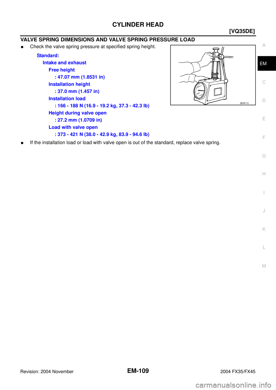
VALVE SPRING DIMENSIONS AND VALVE SPRING PRESSURE LOAD
�Check the valve spring pressure at specified spring height.
�If the installation load or load with valve open is out of the standard, replace valve spring.Standard:
Intake and exhaust
Free height
: 47.07 mm (1.8531 in)
Installation height
: 37.0 mm (1.457 in)
Installation load
: 166 - 188 N (16.9 - 19.2 kg, 37.3 - 42.3 lb)
Height during valve open
: 27.2 mm (1.0709 in)
Load with valve open
: 373 - 421 N (38.0 - 42.9 kg, 83.9 - 94.6 lb)
SEM113
Page 2869 of 4449
![INFINITI FX35 2004 Service Manual EM-144
[VQ35DE]
CYLINDER BLOCK
Revision: 2004 November 2004 FX35/FX45
MAIN BEARING CRUSH HEIGHT
�When main bearing cap is removed after being tightened to the
specified torque with main bearings insta](/manual-img/42/57021/w960_57021-2868.png "INFINITI FX35 2004 Service Manual EM-144
[VQ35DE]
CYLINDER BLOCK
Revision: 2004 November 2004 FX35/FX45
MAIN BEARING CRUSH HEIGHT
�When main bearing cap is removed after being tightened to the
specified torque with main bearings insta")
EM-144
[VQ35DE]
CYLINDER BLOCK
Revision: 2004 November 2004 FX35/FX45
MAIN BEARING CRUSH HEIGHT
�When main bearing cap is removed after being tightened to the
specified torque with main bearings installed, the tip end of bear-
ing must protrude. Refer to EM-126, "
ASSEMBLY" for the tight-
ening procedure.
�If the standard is not met, replace main bearings.
CONNECTING ROD BEARING CRUSH HEIGHT
�When connecting rod bearing cap is removed after being tight-
ened to the specified torque with connecting rod bearings
installed, the tip end of bearing must protrude. Refer to EM-126,
"ASSEMBLY" for the tightening procedure.
�If the standard is not met, replace connecting rod bearings.
MAIN BEARING CAP BOLT OUTER DIAMETER
�Measure outer diameters (“d1”, “d2”) at two positions shown in
the figure.
�Measure “d2” at a point within block “A”.
�When the value of “d1” - “d2” exceeds the limit (a large differ-
ence in dimensions), replace bolt with a new one.
CONNECTING ROD BOLT OUTER DIAMETER
�Measure outer diameter “d” at position shown in the figure.
�If reduction appears in a position other than “d”, regard it as “d”.
�When “d” exceeds the limit (when it becomes thinner), replace
bolt with a new one.Standard : There must be crush height.
SEM502G
Standard : There must be crush height.
PBIC1646E
Limit : 0.11 mm (0.0051 in)
PBIC0911E
Standard : 7.90 - 8.00 mm (0.3110 - 0.3150 in)
Limit : 7.75 mm (0.3051 in)
PBIC0912E
Page 2873 of 4449
![INFINITI FX35 2004 Service Manual EM-148
[VQ35DE]
SERVICE DATA AND SPECIFICATIONS (SDS)
Revision: 2004 November 2004 FX35/FX45
CAMSHAFT AND CAMSHAFT BEARING
Unit: mm (in)
*: Total indicator reading
Valve Lifter
Unit: mm (in)
Valve Cle](/manual-img/42/57021/w960_57021-2872.png "INFINITI FX35 2004 Service Manual EM-148
[VQ35DE]
SERVICE DATA AND SPECIFICATIONS (SDS)
Revision: 2004 November 2004 FX35/FX45
CAMSHAFT AND CAMSHAFT BEARING
Unit: mm (in)
*: Total indicator reading
Valve Lifter
Unit: mm (in)
Valve Cle")
EM-148
[VQ35DE]
SERVICE DATA AND SPECIFICATIONS (SDS)
Revision: 2004 November 2004 FX35/FX45
CAMSHAFT AND CAMSHAFT BEARING
Unit: mm (in)
*: Total indicator reading
Valve Lifter
Unit: mm (in)
Valve Clearance
Unit: mm (in)
*: Approximately 80°C (176°F) ItemsStandard Limit
Camshaft journal to bearing clearanceNo. 1 0.045 - 0.086 (0.0018 - 0.0034)
0.15 (0.0059)
No. 2, 3, 4 0.035 - 0.076 (0.0014 - 0.0030)
Inner diameter of camshaft bearingNo. 1 26.000 - 26.021 (1.0236 - 1.0244) —
No. 2, 3, 4 23.500 - 23.521 (0.9252 - 0.9260) —
Outer diameter of camshaft journalNo. 1 25.935 - 25.955 (1.0211 - 1.0218) —
No. 2, 3, 4 23.445 - 23.465 (0.9230 - 0.9238) —
Camshaft end play 0.115 - 0.188 (0.0045 - 0.0074) 0.24 (0.0094)
Camshaft cam height “A” Intake and exhaust 44.865 - 45.055 (1.7663 - 1.7738) 0.2 (0.008)
Camshaft runout [TIR*] Less than 0.05 (0.0020) —
Camshaft sprocket runout [TIR*] — 0.15 (0.0059)
SEM671
ItemsStandard
Valve lifter outer diameter 33.977 - 33.987 (1.3377 - 1.3381)
Lifter guide inner diameter 34.000 - 34.016 (1.3386 - 1.3392)
Clearance between lifter and lifter guide 0.013 - 0.039 (0.0005 - 0.0015)
Items Cold Hot* (reference data)
Intake 0.26 - 0.34 (0.010 - 0.013) 0.304 - 0.416 (0.012 - 0.016)
Exhaust 0.29 - 0.37 (0.011 - 0.015) 0.308 - 0.432 (0.012 - 0.017)