2004 DAEWOO NUBIRA lock
[x] Cancel search: lockPage 2035 of 2643
MANUAL CONTROL HEATING, VENTILATION AND AIR CONDITIONING SYSTEM 7B – 33
DAEWOO V–121 BL4
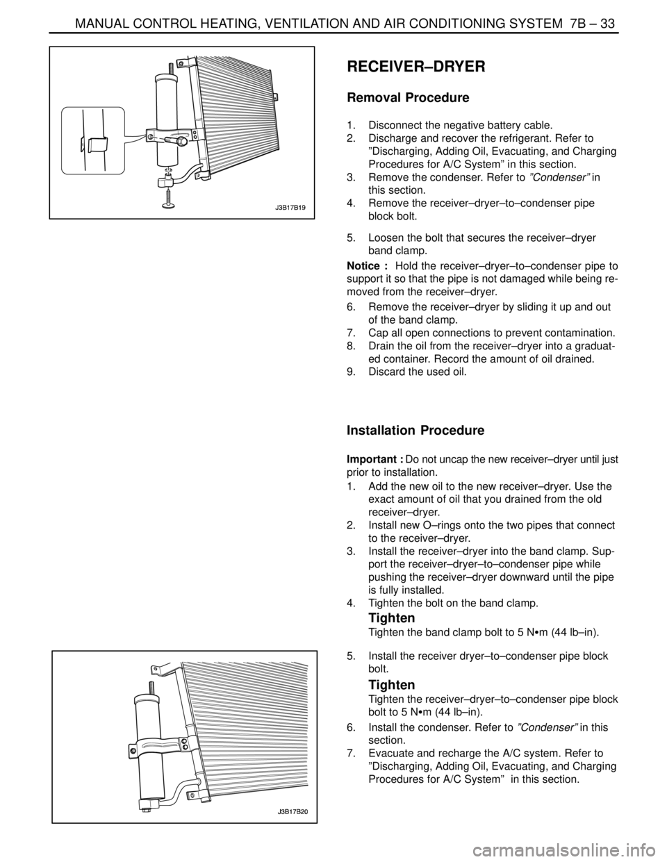
RECEIVER–DRYER
Removal Procedure
1. Disconnect the negative battery cable.
2. Discharge and recover the refrigerant. Refer to
”Discharging, Adding Oil, Evacuating, and Charging
Procedures for A/C System” in this section.
3. Remove the condenser. Refer to ”Condenser” in
this section.
4. Remove the receiver–dryer–to–condenser pipe
block bolt.
5. Loosen the bolt that secures the receiver–dryer
band clamp.
Notice : Hold the receiver–dryer–to–condenser pipe to
support it so that the pipe is not damaged while being re-
moved from the receiver–dryer.
6. Remove the receiver–dryer by sliding it up and out
of the band clamp.
7. Cap all open connections to prevent contamination.
8. Drain the oil from the receiver–dryer into a graduat-
ed container. Record the amount of oil drained.
9. Discard the used oil.
Installation Procedure
Important : Do not uncap the new receiver–dryer until just
prior to installation.
1. Add the new oil to the new receiver–dryer. Use the
exact amount of oil that you drained from the old
receiver–dryer.
2. Install new O–rings onto the two pipes that connect
to the receiver–dryer.
3. Install the receiver–dryer into the band clamp. Sup-
port the receiver–dryer–to–condenser pipe while
pushing the receiver–dryer downward until the pipe
is fully installed.
4. Tighten the bolt on the band clamp.
Tighten
Tighten the band clamp bolt to 5 NSm (44 lb–in).
5. Install the receiver dryer–to–condenser pipe block
bolt.
Tighten
Tighten the receiver–dryer–to–condenser pipe block
bolt to 5 NSm (44 lb–in).
6. Install the condenser. Refer to ”Condenser” in this
section.
7. Evacuate and recharge the A/C system. Refer to
”Discharging, Adding Oil, Evacuating, and Charging
Procedures for A/C System” in this section.
Page 2036 of 2643
7B – 34IMANUAL CONTROL HEATING, VENTILATION AND AIR CONDITIONING SYSTEM
DAEWOO V–121 BL4
COMPRESSOR
Removal Procedure
1. Disconnect the negative battery cable.
2. Discharge and recover the refrigerant. Refer to
”Discharging, Adding Oil, Evacuating, and Charging
Procedures for A/C System” in this section.
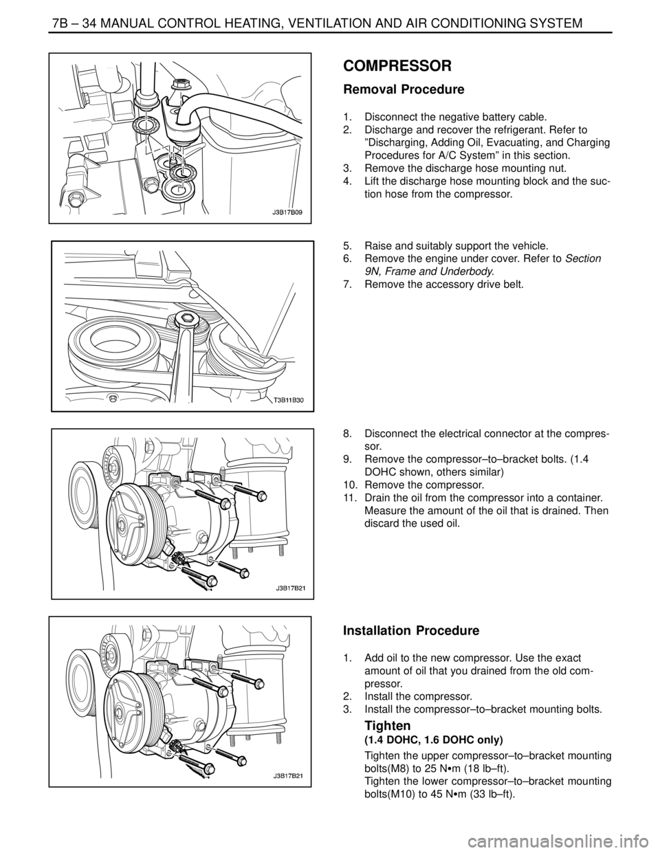
3. Remove the discharge hose mounting nut.
4. Lift the discharge hose mounting block and the suc-
tion hose from the compressor.
5. Raise and suitably support the vehicle.
6. Remove the engine under cover. Refer to Section
9N, Frame and Underbody.
7. Remove the accessory drive belt.
8. Disconnect the electrical connector at the compres-
sor.
9. Remove the compressor–to–bracket bolts. (1.4
DOHC shown, others similar)
10. Remove the compressor.
11. Drain the oil from the compressor into a container.
Measure the amount of the oil that is drained. Then
discard the used oil.
Installation Procedure
1. Add oil to the new compressor. Use the exact
amount of oil that you drained from the old com-
pressor.
2. Install the compressor.
3. Install the compressor–to–bracket mounting bolts.
Tighten
(1.4 DOHC, 1.6 DOHC only)
Tighten the upper compressor–to–bracket mounting
bolts(M8) to 25 NSm (18 lb–ft).
Tighten the lower compressor–to–bracket mounting
bolts(M10) to 45 NSm (33 lb–ft).
Page 2037 of 2643
MANUAL CONTROL HEATING, VENTILATION AND AIR CONDITIONING SYSTEM 7B – 35
DAEWOO V–121 BL4
Tighten
(1.8 DOHC, 2.0 DOHC only)
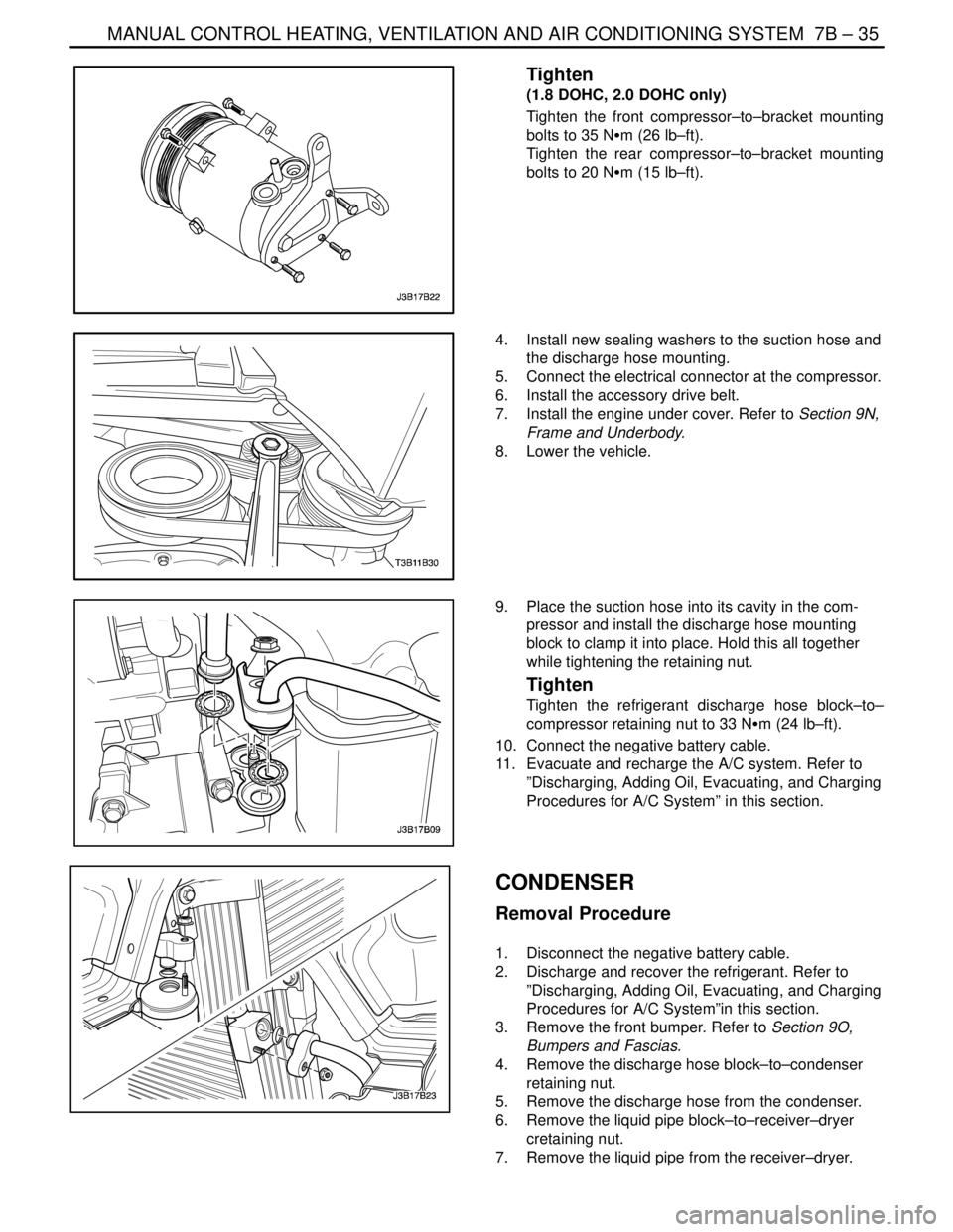
Tighten the front compressor–to–bracket mounting
bolts to 35 NSm (26 lb–ft).
Tighten the rear compressor–to–bracket mounting
bolts to 20 NSm (15 lb–ft).
4. Install new sealing washers to the suction hose and
the discharge hose mounting.
5. Connect the electrical connector at the compressor.
6. Install the accessory drive belt.
7. Install the engine under cover. Refer to Section 9N,
Frame and Underbody.
8. Lower the vehicle.
9. Place the suction hose into its cavity in the com-
pressor and install the discharge hose mounting
block to clamp it into place. Hold this all together
while tightening the retaining nut.
Tighten
Tighten the refrigerant discharge hose block–to–
compressor retaining nut to 33 NSm (24 lb–ft).
10. Connect the negative battery cable.
11. Evacuate and recharge the A/C system. Refer to
”Discharging, Adding Oil, Evacuating, and Charging
Procedures for A/C System” in this section.
CONDENSER
Removal Procedure
1. Disconnect the negative battery cable.
2. Discharge and recover the refrigerant. Refer to
”Discharging, Adding Oil, Evacuating, and Charging
Procedures for A/C System”in this section.
3. Remove the front bumper. Refer to Section 9O,
Bumpers and Fascias.
4. Remove the discharge hose block–to–condenser
retaining nut.
5. Remove the discharge hose from the condenser.
6. Remove the liquid pipe block–to–receiver–dryer
cretaining nut.
7. Remove the liquid pipe from the receiver–dryer.
Page 2038 of 2643
7B – 36IMANUAL CONTROL HEATING, VENTILATION AND AIR CONDITIONING SYSTEM
DAEWOO V–121 BL4
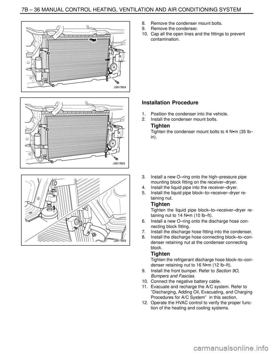
8. Remove the condenser mount bolts.
9. Remove the condenser.
10. Cap all the open lines and the fittings to prevent
contamination.
Installation Procedure
1. Position the condenser into the vehicle.
2. Install the condenser mount bolts.
Tighten
Tighten the condenser mount bolts to 4 NSm (35 lb–
in).
3. Install a new O–ring onto the high–pressure pipe
mounting block fitting on the receiver–dryer.
4. Install the liquid pipe into the receiver–dryer.
5. Install the liquid pipe block–to–receiver–dryer re-
taining nut.
Tighten
Tighten the liquid pipe block–to–receiver–dryer re-
taining nut to 14 NSm (10 lb–ft).
6. Install a new O–ring onto the discharge hose con-
necting block fitting.
7. Install the discharge hose fitting into the condenser.
8. Install the discharge hose connecting block–to–con-
denser retaining nut at the condenser connecting
block.
Tighten
Tighten the refrigerant discharge hose block–to–con-
denser retaining nut to 16 NSm (12 lb–ft).
9. Install the front bumper. Refer to Section 9O,
Bumpers and Fascias.
10. Connect the negative battery cable.
11. Evacuate and recharge the A/C system. Refer to
”Discharging, Adding Oil, Evacuating, and Charging
Procedures for A/C System” in this section.
12. Operate the HVAC control to verify the proper func-
tion of the heating and cooling systems.
Page 2042 of 2643
7B – 40IMANUAL CONTROL HEATING, VENTILATION AND AIR CONDITIONING SYSTEM
DAEWOO V–121 BL4
11. Remove the compressor from the bench vise and
remove the J–34992 compressor holding fixture
from the compressor.
12. Install the compressor. Refer to ”Compressor” in
this section.
CLUTCH ROTOR AND BEARING
Tools Required
J–6083 Snap Ring Pliers
J–9398–A Bearing Remover
J–9481 Bearing Installer
J–33020 Pulley Puller
J–33023–A Puller Pilot
J–33019 Bearing Staking Tool Set
Includes: J–33019–1 Bearing Staking Guide
Includes: J–33019–2 Bearing Staking Pin
Includes: J–33019–1 Bearing Staking Guide
J–33017 Pulley Rotor and Bearing Installer
J–8433–1 Puller Crossbar
J–34992 Compressor Holding Fixture
J–8092 Driver Handle
J–8433–3 Forcing Screw
Disassembly Procedure
1. Disconnect the negative battery cable.
2. Recover the refrigerant. Refer to ”Discharging,
Adding Oil, Evacuating, and Charging for A/C Sys-
tem” in this section.
3. Remove the compressor. Refer to ”Compressor” in
this section.
4. Remove the clutch drive plate and hub assembly.
Refer to ”Clutch Plate and Hub Assembly” in this
section.
5. Remove the pulley rotor and bearing assembly re-
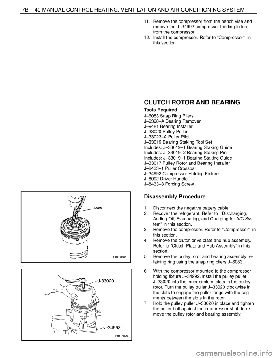
taining ring using the snap ring pliers J–6083.
6. With the compressor mounted to the compressor
holding fixture J–34992, install the pulley puller
J–33020 into the inner circle of slots in the pulley
rotor. Turn the pulley puller J–33020 clockwise in
the slots to engage the puller tangs with the seg-
ments between the slots in the rotor.
7. Hold the pulley puller J–33020 in place and tighten
the puller bolt against the compressor shaft to re-
move the pulley rotor and bearing assembly.
Page 2043 of 2643
MANUAL CONTROL HEATING, VENTILATION AND AIR CONDITIONING SYSTEM 7B – 41
DAEWOO V–121 BL4
Notice : The rotor hub must be properly supported to pre-
vent damage to the pulley rotor during bearing removal.
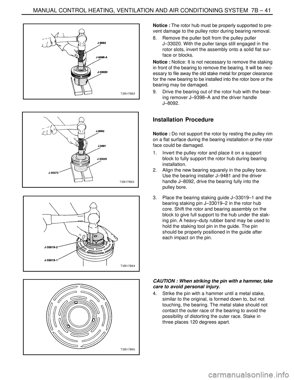
8. Remove the puller bolt from the pulley puller
J–33020. With the puller tangs still engaged in the
rotor slots, invert the assembly onto a solid flat sur-
face or blocks.
Notice : Notice: It is not necessary to remove the staking
in front of the bearing to remove the bearing. It will be nec-
essary to file away the old stake metal for proper clearance
for the new bearing to be installed into the rotor bore or the
bearing may be damaged.
9. Drive the bearing out of the rotor hub with the bear-
ing remover J–9398–A and the driver handle
J–8092.
Installation Procedure
Notice : Do not support the rotor by resting the pulley rim
on a flat surface during the bearing installation or the rotor
face could be damaged.
1. Invert the pulley rotor and place it on a support
block to fully support the rotor hub during bearing
installation.
2. Align the new bearing squarely in the pulley bore.
Use the bearing installer J–9481 and the driver
handle J–8092, drive the bearing fully into the
pulley bore.
3. Place the bearing staking guide J–33019–1 and the
bearing staking pin J–33019–2 in the rotor hub
core. Shift the rotor and bearing assembly on the
block to give full support to the hub under the stak-
ing pin. A heavy–duty rubber band may be used to
hold the staking tool pin in the guide. The pin
should be properly positioned in the guide after
each impact on the pin.
CAUTION : When striking the pin with a hammer, take
care to avoid personal injury.
4. Strike the pin with a hammer until a metal stake,
similar to the original, is formed down to, but not
touching, the bearing. The metal stake should not
contact the outer race of the bearing to avoid the
possibility of distorting the outer race. Stake in
three places 120 degrees apart.
Page 2046 of 2643
7B – 44IMANUAL CONTROL HEATING, VENTILATION AND AIR CONDITIONING SYSTEM
DAEWOO V–121 BL4
SHAFT SEAL REPLACEMENT
Tools Required
J–5403 Snap Ring Pliers
J–9553–1 O–Ring Remover
J–23128–A Seal Seat Remover/Installer
J–33011 O–Ring Installer
J–34614 Shaft Seal Protector
Important : A shaft seal should not be replaced because
a small amount of oil is found on the adjacent surface. The
seal is designed to leak some oil for lubrication purposes.
A shaft seal should be changed only when a large amount
of sprayed oil is found and then only after actual refrigerant
leakage is found by using an approved leak detection pro-
cedure. Refer to ”Leak Testing the Refrigerant System” in
this section.
Should a compressor shaft seal ever have to be replaced,
the receiver–dryer in this system must also be removed
from the vehicle. The oil in the receiver–dryer must then
be drained, measured and replaced. Refer to ”Discharg-
ing, Adding Oil, Evacuating, and Charging Procedures for
A/C System” in this section.
Removal Procedure
1. Disconnect the negative battery cable.
2. Recover the refrigerant. Refer to ”Discharging, Add-
ing Oil, Evacuating, and Charging Procedures for
A/C System” in this section.
3. Loosen and reposition the compressor in the
mounting brackets.
4. Remove the clutch drive plate and hub assembly
from the compressor. Refer to ”Clutch Plate and
Hub Assembly” in this section.
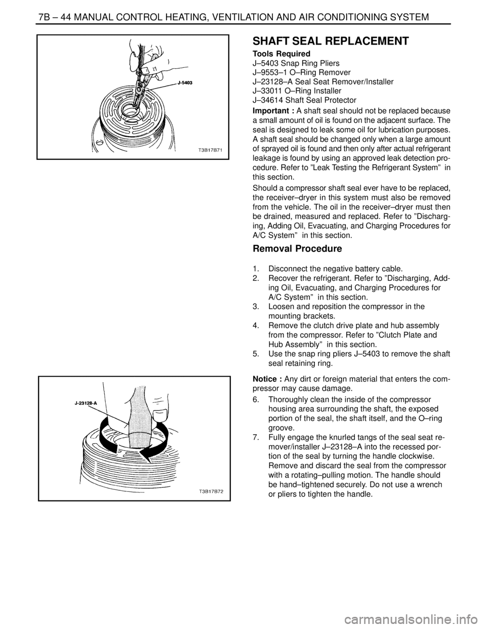
5. Use the snap ring pliers J–5403 to remove the shaft
seal retaining ring.
Notice : Any dirt or foreign material that enters the com-
pressor may cause damage.
6. Thoroughly clean the inside of the compressor
housing area surrounding the shaft, the exposed
portion of the seal, the shaft itself, and the O–ring
groove.
7. Fully engage the knurled tangs of the seal seat re-
mover/installer J–23128–A into the recessed por-
tion of the seal by turning the handle clockwise.
Remove and discard the seal from the compressor
with a rotating–pulling motion. The handle should
be hand–tightened securely. Do not use a wrench
or pliers to tighten the handle.
Page 2049 of 2643
MANUAL CONTROL HEATING, VENTILATION AND AIR CONDITIONING SYSTEM 7B – 47
DAEWOO V–121 BL4
REAR HEAD, GASKET, VALVE
PLATE, REED PLATE, AND O–RING
Tools Required
J–34993 Cylinder Alignment Rods
Removal Procedure
1. Recover the refrigerant. Refer to ”Discharging, Add-
ing Oil, Evacuating, and Charging Procedures for
A/C System” in this section.
2. Discharge the A/C system. Refer to ”Discharging,
Adding Oil, Evacuating, and Charging Procedures
for A/C System” in this section.
3. Remove the compressor. Refer to ”Compressor” in
this section.
4. Drain the oil from compressor into a suitable con-
tainer. Measure and record the amount of oil
drained from the compressor. Discard the used oil.
5. Remove the clutch plate and hub assembly. Refer
to ”Clutch Plate and Hub Assembly” in this section.
6. Remove the clutch rotor and bearing. Refer to
”Clutch Rotor and Bearing” in this section.
7. Remove the clutch coil. Refer to ”Clutch Coil” in
this section.
8. Remove the compressor through–bolts. Remove
and discard the gaskets.
9. Using a wooden block and a plastic–headed ham-
mer, tap around the edge of the rear head to disen-
gage the head from the compressor cylinder. Sepa-
rate the rear head, the head gasket, the rear valve
plate, the suction reed plate, and the cylinder–to–
rear head O–ring. Discard the head gasket and the
O–ring.
Installation Procedure
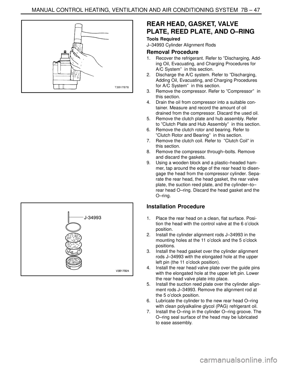
1. Place the rear head on a clean, flat surface. Posi-
tion the head with the control valve at the 6 o’clock
position.
2. Install the cylinder alignment rods J–34993 in the
mounting holes at the 11 o’clock and the 5 o’clock
positions.
3. Install the head gasket over the cylinder alignment
rods J–34993 with the elongated hole at the upper
left pin (the 11 o’clock position).
4. Install the rear head valve plate over the guide pins
with the elongated hole at the upper left pin. Lower
the rear head valve plate into place.
5. Install the suction reed plate over the cylinder align-
ment rods J–34993. Remove the alignment rod at
the 5 o’clock position.
6. Lubricate the cylinder to the new rear head O–ring
with clean polyalkaline glycol (PAG) refrigerant oil.
7. Install the O–ring in the cylinder O–ring groove. The
O–ring seal surface of the head may be lubricated
to ease assembly.