2004 DAEWOO NUBIRA lock
[x] Cancel search: lockPage 1947 of 2643

6C – 30IPOWER STEERING GEAR
DAEWOO V–121 BL4
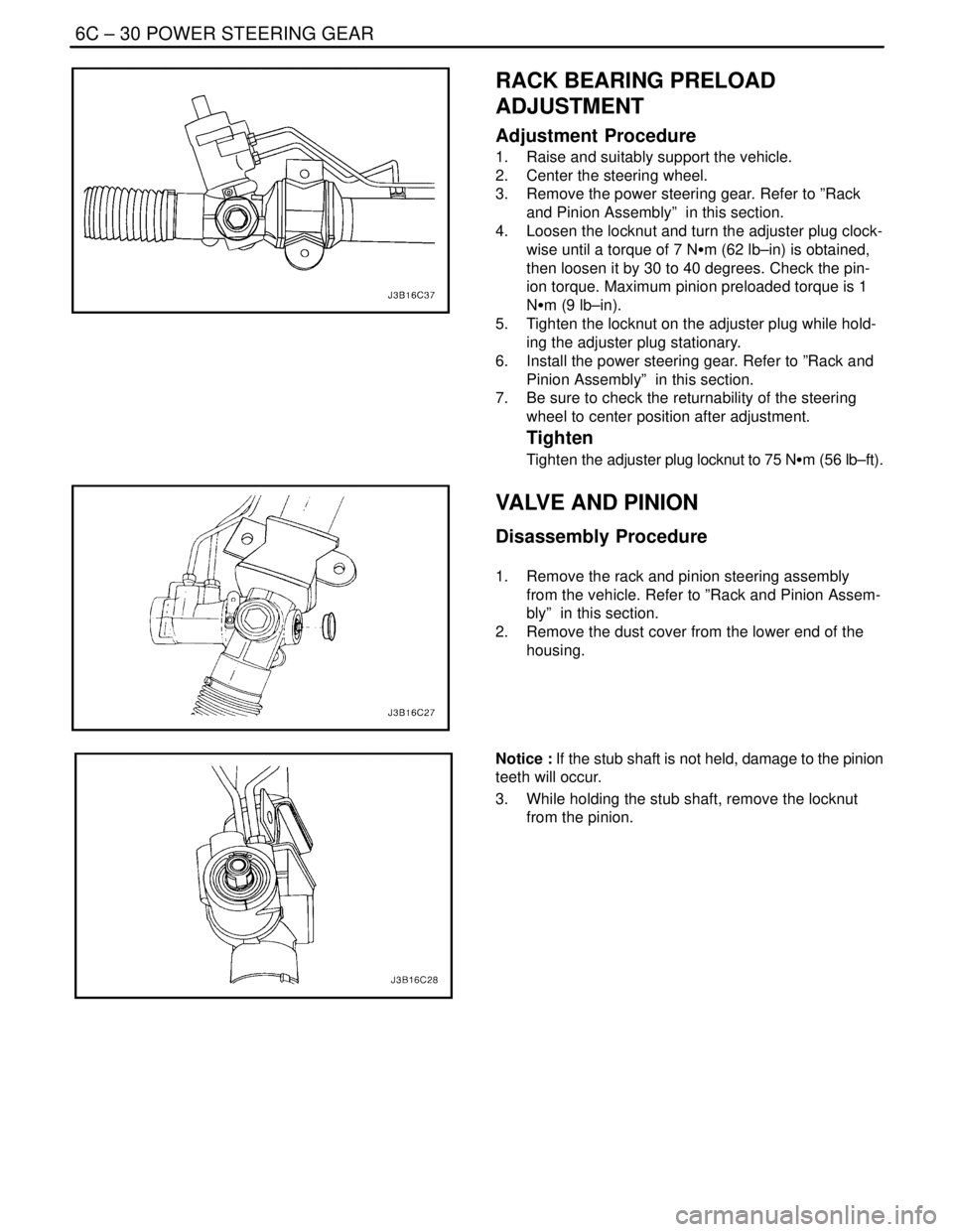
RACK BEARING PRELOAD
ADJUSTMENT
Adjustment Procedure
1. Raise and suitably support the vehicle.
2. Center the steering wheel.
3. Remove the power steering gear. Refer to ”Rack
and Pinion Assembly” in this section.
4. Loosen the locknut and turn the adjuster plug clock-
wise until a torque of 7 NSm (62 lb–in) is obtained,
then loosen it by 30 to 40 degrees. Check the pin-
ion torque. Maximum pinion preloaded torque is 1
NSm (9 lb–in).
5. Tighten the locknut on the adjuster plug while hold-
ing the adjuster plug stationary.
6. Install the power steering gear. Refer to ”Rack and
Pinion Assembly” in this section.
7. Be sure to check the returnability of the steering
wheel to center position after adjustment.
Tighten
Tighten the adjuster plug locknut to 75 NSm (56 lb–ft).
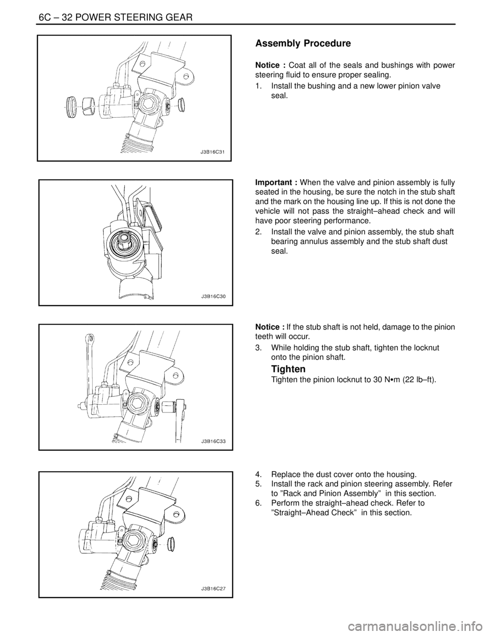
VALVE AND PINION
Disassembly Procedure
1. Remove the rack and pinion steering assembly
from the vehicle. Refer to ”Rack and Pinion Assem-
bly” in this section.
2. Remove the dust cover from the lower end of the
housing.
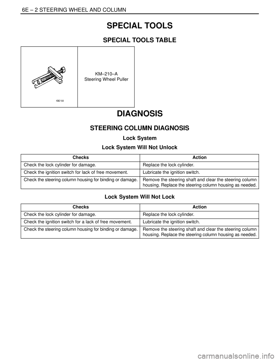
Notice : If the stub shaft is not held, damage to the pinion
teeth will occur.
3. While holding the stub shaft, remove the locknut
from the pinion.
Page 1949 of 2643

6C – 32IPOWER STEERING GEAR
DAEWOO V–121 BL4
Assembly Procedure
Notice : Coat all of the seals and bushings with power
steering fluid to ensure proper sealing.
1. Install the bushing and a new lower pinion valve
seal.
Important : When the valve and pinion assembly is fully
seated in the housing, be sure the notch in the stub shaft
and the mark on the housing line up. If this is not done the
vehicle will not pass the straight–ahead check and will
have poor steering performance.
2. Install the valve and pinion assembly, the stub shaft
bearing annulus assembly and the stub shaft dust
seal.
Notice : If the stub shaft is not held, damage to the pinion
teeth will occur.
3. While holding the stub shaft, tighten the locknut
onto the pinion shaft.
Tighten
Tighten the pinion locknut to 30 NSm (22 lb–ft).
4. Replace the dust cover onto the housing.
5. Install the rack and pinion steering assembly. Refer
to ”Rack and Pinion Assembly” in this section.
6. Perform the straight–ahead check. Refer to
”Straight–Ahead Check” in this section.
Page 1950 of 2643

POWER STEERING GEAR 6C – 33
DAEWOO V–121 BL4
GENERAL DESCRIPTION
AND SYSTEM OPERATION
POWER RACK AND PINION
The power rack and pinion steering system has a rotary
control valve that directs hydraulic fluid coming from the
hydraulic pump to one side or the other side of the rack pis-
ton. The integral rack piston is attached to the rack. The
rack piston converts hydraulic pressure to a linear force
that moves the rack left or right. That force is then trans-
mitted through the tie rods to the steering knuckles, which
turn the wheels.
If power rack and pinion steering is not available, manual
rack and pinion control is used; however, with this system,
more steering effort is required. The movement of the
steering wheel is transferred to the pinion. The rotary
movement of the pinion is then transferred through the pin-
ion threads, which mesh with teeth on the rack, thereby
causing the rack to move in a linear direction.
A vane–type of hydraulic pump provides hydraulic pres-
sure for both steering systems.
SPEED SENSITIVE POWER
STEERING SYSTEM
The speed sensitive power steering (SSPS) system varies
the driver effort required to steer as the vehicle speed
changes. At low speeds, the system provides maximum
power assist for easy turning and parking maneuvers. At
higher speeds, the steering power is reduced to provide
the driver with firmer steering and directional stability. The
SSPS system accomplishes this by reducing the amount
of power steering fluid flow from the power steering pump
to the power steering gear as the vehicle speed increases.
When the vehicle is stationary, the SSPS system provides
maximum fluid flow to the steering gear. As the vehicle
speed increases, the fluid flow to the steering gear is de-
creased.
Control Module
The SSPS control module processes the vehicle speed in-
formation from the engine control module (ECM) and uses
the steering wheel rotation sensor to provide a control sig-
nal to the electronic variable orifice (EVO) actuator located
on the power steering pump.
Electronic Variable Orifice (EVO) Actuator
The electronic variable orifice (EVO) actuator is located on
the power steering pump and contains a solenoid– oper-
ated pintle valve. Fluid leaving the pump passes through
an orifice in the actuator tip. When the EVO actuator is
powered by the SSPS control module, the pintle moves
into the orifice and reduces the power steering fluid flow.As the vehicle speed increases, current from the SSPS
control module increases, and the pintle blocks more and
more of the orifice.
Steering Wheel Rotation Sensor
The steering wheel rotation sensor is located at the end of
the steering column housing and is used to send a signal
to the controller when abrupt or evasive steering maneu-
vers are needed.
Power Steering Pressure Hose
SSPS vehicles have a specific pressure hose assembly
which includes an in–line check valve in the rack and pin-
ion assembly. This reduces the amount of steering wheel
”kick” when driving over irregular road surfaces while oper-
ating at speeds with reduced flow rate and pressure.
Power Rack and Pinion
Except for differences in valve machining, the design of
the SSPS power rack and pinion assembly is the same as
for the a non–SSPS system. The steering wheel move-
ment is transferred to the pinion via the intermediate shaft.
The pinion moves the rack left or right through meshing the
pinion and the rack teeth. The force is then transmitted
through the tie rods and steering knuckle to steer the
wheels.
The power rack and pinion steering system has a rotary
control valve which directs the hydraulic fluid from the
power steering pump to one side or the other side of the
rack piston. The piston is attached to the rack and uses hy-
draulic pressure to move the rack left or right. The rotary
control valve regulates the degree of assist by responding
to the driver’s torque input.
If hydraulic assist is not available, manual control is main-
tained. However, under this condition, more steering effort
is required.
Power Steering Pump
The standard vane–type pump, which provides hydraulic
pressure for the system, incorporates a special discharge
fitting to hold the EVO actuator.
System Operation
System operation originates with input from the vehicle
speed sensor via the engine control module to the SSPS
control module. The SSPS control module sends a signal
to the SSPS actuator to vary the rate of fluid flow output
by the power steering pump.
Circuit Operation
The SSPS system uses inputs from the speed sensor and
steering wheel rotation sensor to the SSPS controller to
determine the desired amount of power steering assist.
The SSPS control module constantly compares the
amount of current flowing through the EVO actuator to the
desired current it has calculated. The EVO actuator has a
pintle that moves in and out of an orifice, regulating power
Page 1955 of 2643

SECTION : 6E
STEERING WHEEL AND COLUMN
CAUTION : Disconnect the negative battery cable before removing or installing any electrical unit or when a tool
or equipment could easily come in contact with exposed electrical terminals. Disconnecting this cable will help
prevent personal injury and damage to the vehicle. The ignition must also be in LOCK unless otherwise noted.
TABLE OF CONTENTS
SPECIFICATIONS6E–1 . . . . . . . . . . . . . . . . . . . . . . . . . .
Fastener Tightening Specifications 6E–1. . . . . . . . . . .
SPECIAL TOOLS6E–2 . . . . . . . . . . . . . . . . . . . . . . . . . . .
Special Tools Table 6E–2. . . . . . . . . . . . . . . . . . . . . . . .
DIAGNOSIS6E–2 . . . . . . . . . . . . . . . . . . . . . . . . . . . . . . . .
Steering Column Diagnosis 6E–2. . . . . . . . . . . . . . . . .
MAINTENANCE AND REPAIR6E–8 . . . . . . . . . . . . . . .
ON–VEHICLE SERVICE 6E–8. . . . . . . . . . . . . . . . . . . . .
Headlamp/Turn Signal Switch and Lever 6E–8. . . . . .
Wiper Switch and Lever 6E–9. . . . . . . . . . . . . . . . . . . . Steering Wheel Rotation Sensor 6E–10. . . . . . . . . . . .
Steering Wheel Without SIR 6E–11. . . . . . . . . . . . . . . .
Steering Wheel With SIR 6E–13. . . . . . . . . . . . . . . . . .
Ignition Lock Cylinder and Switch 6E–13. . . . . . . . . . .
Steering Column 6E–15. . . . . . . . . . . . . . . . . . . . . . . . . .
UNIT REPAIR 6E–19. . . . . . . . . . . . . . . . . . . . . . . . . . . . .
Tilt Steering Column 6E–19. . . . . . . . . . . . . . . . . . . . . .
GENERAL DESCRIPTION AND SYSTEM
OPERATION6E–20 . . . . . . . . . . . . . . . . . . . . . . . . . . . . .
Steering Wheel and Column 6E–20. . . . . . . . . . . . . . . .
Ignition Key Reminder 6E–20. . . . . . . . . . . . . . . . . . . . .
SPECIFICATIONS
FASTENER TIGHTENING SPECIFICATIONS
ApplicationNSmLb–FtLb–In
Ignition Switch Housing Shear Bolts11–97
Ignition Switch Retaining Screw2.5–22
Steering Column Jacket Assembly Front Bracket Bolts2216–
Steering Column Jacket Assembly Rear Bracket Nuts2216–
Steering Shaft Universal Joint Pinch Bolt2518–
Steering Wheel Horn Cap Screws4.5–40
Steering Wheel Nut3828–
Steering Wheel Rotation Sensor Retaining Screw2–18
Support Housing Screws1612–
Turn Signal Switch Housing Screws3–27
Upper and Lower Steering Column Cover Panel Screws2.5–22
Page 1956 of 2643

6E – 2ISTEERING WHEEL AND COLUMN
DAEWOO V–121 BL4
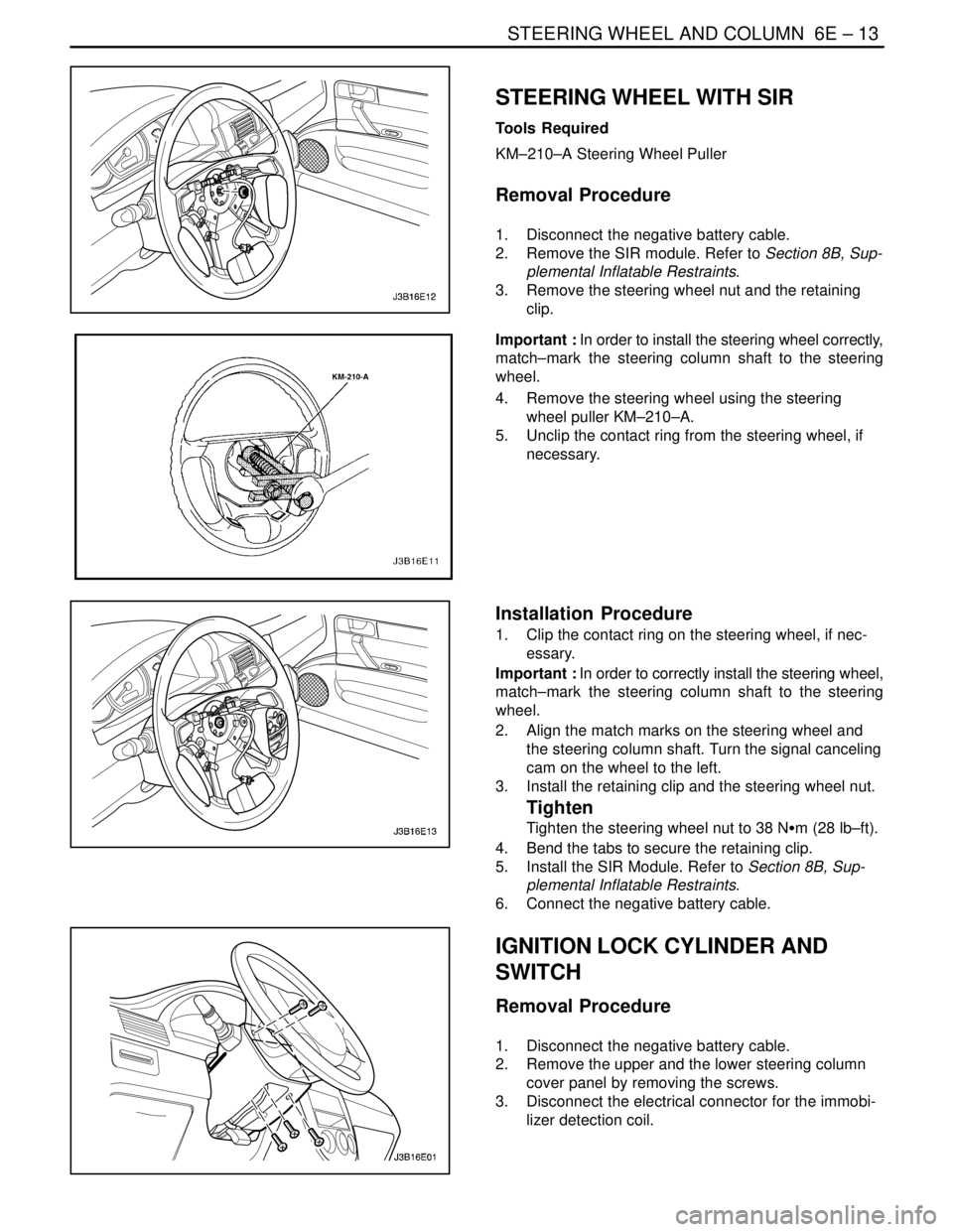
SPECIAL TOOLS
SPECIAL TOOLS TABLE
KM–210–A
Steering Wheel Puller
DIAGNOSIS
STEERING COLUMN DIAGNOSIS
Lock System
Lock System Will Not Unlock
ChecksAction
Check the lock cylinder for damage.Replace the lock cylinder.
Check the ignition switch for lack of free movement.Lubricate the ignition switch.
Check the steering column housing for binding or damage.Remove the steering shaft and clear the steering column
housing. Replace the steering column housing as needed.
Lock System Will Not Lock
ChecksAction
Check the lock cylinder for damage.Replace the lock cylinder.
Check the ignition switch for a lack of free movement.Lubricate the ignition switch.
Check the steering column housing for binding or damage.Remove the steering shaft and clear the steering column
housing. Replace the steering column housing as needed.
Page 1957 of 2643

STEERING WHEEL AND COLUMN 6E – 3
DAEWOO V–121 BL4
High Lock Effort
ChecksAction
Check the lock cylinder for damage.Replace the lock cylinder.
Check the ignition switch for lack of free movement.Lubricate the ignition switch.
Check for extreme misalignment of the housing to the cov-
er.Realign the cover on the housing. Replace the cover as
needed.
Check for a bent ignition switch mounting bracket.Replace the ignition switch mounting bracket.
Key Cannot Be Removed in the LOCK Position
ChecksAction
Check to see that the ignition switch is set correctly.Reset the ignition switch.
Check the lock cylinder for damage.Replace the lock cylinder.
Check the fuse F17 from the I/P fuse block.Replace the fuse F17
Check for an open or short in the circuit between terminal
2 of key interlock solenoid and the I/P fuse block.Replace the fuse F17
Select the gear shift lever to ”P” position.
Check the resistance between the terminal 2 and 1 of the
”P” position switch.Replace the ”P” position switch.
Check for an open or short in the circuit between the
ground G202 and terminal 1 of the key interlock unit.Replace the open or short from the circuit.
Turn the ignition ON.
Select the gear shift lever to ”P” position.
Check the resistance between the terminal 1 and 2 of the
key interlock solenoid.Replace the key interlock solenoid.
Page 1959 of 2643

STEERING WHEEL AND COLUMN 6E – 5
DAEWOO V–121 BL4
Column
Noise in the Column
ChecksAction
Check the steering gear–to–column joints for improper
installation.Tighten the steering shaft universal joint pinch bolts.
Replace the steering shaft joints as needed.
Check the steering shaft bearing for wear or damage.Replace the steering shaft bearing.
Check the spherical joint for lack of lubrication.Lubricate the spherical joint.
Check the steering shaft for lack of lubrication.Lubricate the steering shaft bearing.
Check the shaft lock snap ring for improper seating.Adjust the shaft lock snap ring. Replace the shaft lock snap
ring as needed.
High Steering Shaft Effort
ChecksAction
Check the steering shaft bearing for wear or damage.Replace the steering shaft bearing.
Check for an improperly installed or deformed dust seal.Replace the dust seal.
Check for a damaged upper or lower bearing.Replace the upper or the lower bearing.
Check the steering shaft universal joints for a lack of free
movement.Lubricate the steering shaft universal joints. Replace the
steering shaft universal joints as needed.
Lash in the Steering Column
ChecksAction
Check the steering column bracket mounting bolts for im-
proper installation.Tighten the steering column bracket mounting bolts.
Check for broken weld nuts on the steering column jacket.Replace the steering column jacket.
Check for loose steering column housing–to–steering col-
umn jacket support screws.Tighten the support screws.
Loose Steering Wheel
ChecksAction
Check for excessive clearance between the holes in the
steering wheel support or the housing and the pivot–pin di-
ameters.Replace the pivot pins with pivot pins of the correct size.
Check to see if the upper bearing is seated correctly in the
housing.Correctly seat the upper bearing. Replace the upper bear-
ing as needed.
Check for loose steering column housing support screws.Tighten the steering column housing support screws.
Noise When Tilting the Column
ChecksAction
Check for worn upper tilt bumpers.Replace the upper tilt bumpers.
Check for tilt spring binding.Adjust the tilt spring. Replace the tilt spring as needed.
Page 1967 of 2643

STEERING WHEEL AND COLUMN 6E – 13
DAEWOO V–121 BL4
STEERING WHEEL WITH SIR
Tools Required
KM–210–A Steering Wheel Puller
Removal Procedure
1. Disconnect the negative battery cable.
2. Remove the SIR module. Refer to Section 8B, Sup-
plemental Inflatable Restraints.
3. Remove the steering wheel nut and the retaining
clip.
Important : In order to install the steering wheel correctly,
match–mark the steering column shaft to the steering
wheel.
4. Remove the steering wheel using the steering
wheel puller KM–210–A.
5. Unclip the contact ring from the steering wheel, if
necessary.
Installation Procedure
1. Clip the contact ring on the steering wheel, if nec-
essary.
Important : In order to correctly install the steering wheel,
match–mark the steering column shaft to the steering
wheel.
2. Align the match marks on the steering wheel and
the steering column shaft. Turn the signal canceling
cam on the wheel to the left.
3. Install the retaining clip and the steering wheel nut.
Tighten
Tighten the steering wheel nut to 38 NSm (28 lb–ft).
4. Bend the tabs to secure the retaining clip.
5. Install the SIR Module. Refer to Section 8B, Sup-
plemental Inflatable Restraints.
6. Connect the negative battery cable.
IGNITION LOCK CYLINDER AND
SWITCH
Removal Procedure
1. Disconnect the negative battery cable.
2. Remove the upper and the lower steering column
cover panel by removing the screws.
3. Disconnect the electrical connector for the immobi-
lizer detection coil.