2004 DAEWOO NUBIRA lock
[x] Cancel search: lockPage 173 of 2643

1.8L DOHC ENGINE MECHANICAL 1C2 – 53
DAEWOO V–121 BL4
8. Inspect the piston for fit to the connecting rod.
9. Inspect the engine block deck surface for flatness
using a straight edge and a feeler gauge. Refer to
”Engine Specifications” in this section.
10. Inspect the bearing bore for concentricity and align-
ment using cylinder bore check gauge J–8087. Re-
fer to ”Engine Specifications” in this section. If the
bearing bore is beyond specifications, replace the
engine block.
11. Inspect the engine block cylinder bore for wear,
runout, ridging and taper using a bore gauge. Refer
to ”Engine Specifications” in this section.
12. Inspect the engine block cylinder bore for glazing.
Lightly hone the cylinder bore as necessary.
Installation Procedure
Important : For ease of installation of the piston pin, the
connecting rod should be heated to 2805C. Heat the upper
connecting rod only. Use commercial thermocolor materi-
al to determine the correct temperature. When the thermo-
color material changes from black to green, the tempera-
ture is correct for installation.
1. Align the notch on the piston and connecting rod so
that the proper sides will be facing the front of the
engine.
2. Install the piston pin guide through the piston and
the connecting rod.
3. Coat the piston pin with clean oil.
4. Install the piston pin into the opposite side of the
piston.
5. Install the piston pin into the piston and connecting
rod assembly using the piston pin service set
KM–427.
6. Select a set of new piston rings.
7. Measure the piston ring gap using a feeler gauge.
Refer to ”Engine Specifications” in this section.
8. Increase the piston ring gap by carefully filing off
excess material if the piston ring gap is below spec-
ifications.
Page 180 of 2643
1C2 – 60I1.8L DOHC ENGINE MECHANICAL
DAEWOO V–121 BL4
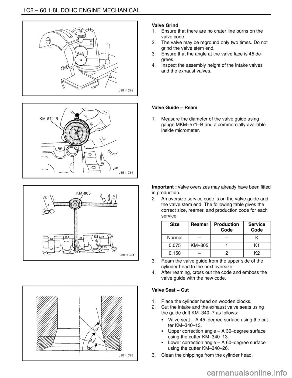
Valve Grind
1. Ensure that there are no crater line burns on the
valve cone.
2. The valve may be reground only two times. Do not
grind the valve stem end.
3. Ensure that the angle at the valve face is 45 de-
grees.
4. Inspect the assembly height of the intake valves
and the exhaust valves.
Valve Guide – Ream
1. Measure the diameter of the valve guide using
gauge MKM–571–B and a commercially available
inside micrometer.
Important : Valve oversizes may already have been fitted
in production.
2. An oversize service code is on the valve guide and
the valve stem end. The following table gives the
correct size, reamer, and production code for each
service.
Size
ReamerProduction
CodeService
Code
Normal––K
0.075KM–8051K1
0.150–2K2
3. Ream the valve guide from the upper side of the
cylinder head to the next oversize.
4. After reaming, cross out the code and emboss the
valve guide with the new code.
Valve Seat – Cut
1. Place the cylinder head on wooden blocks.
2. Cut the intake and the exhaust valve seats using
the guide drift KM–340–7 as follows:
S Valve seat – A 45–degree surface using the cut-
ter KM–340–13.
S Upper correction angle – A 30–degree surface
using the cutter KM–340–13.
S Lower correction angle – A 60–degree surface
using the cutter KM–340–26.
3. Clean the chippings from the cylinder head.
Page 184 of 2643
1C2 – 64I1.8L DOHC ENGINE MECHANICAL
DAEWOO V–121 BL4
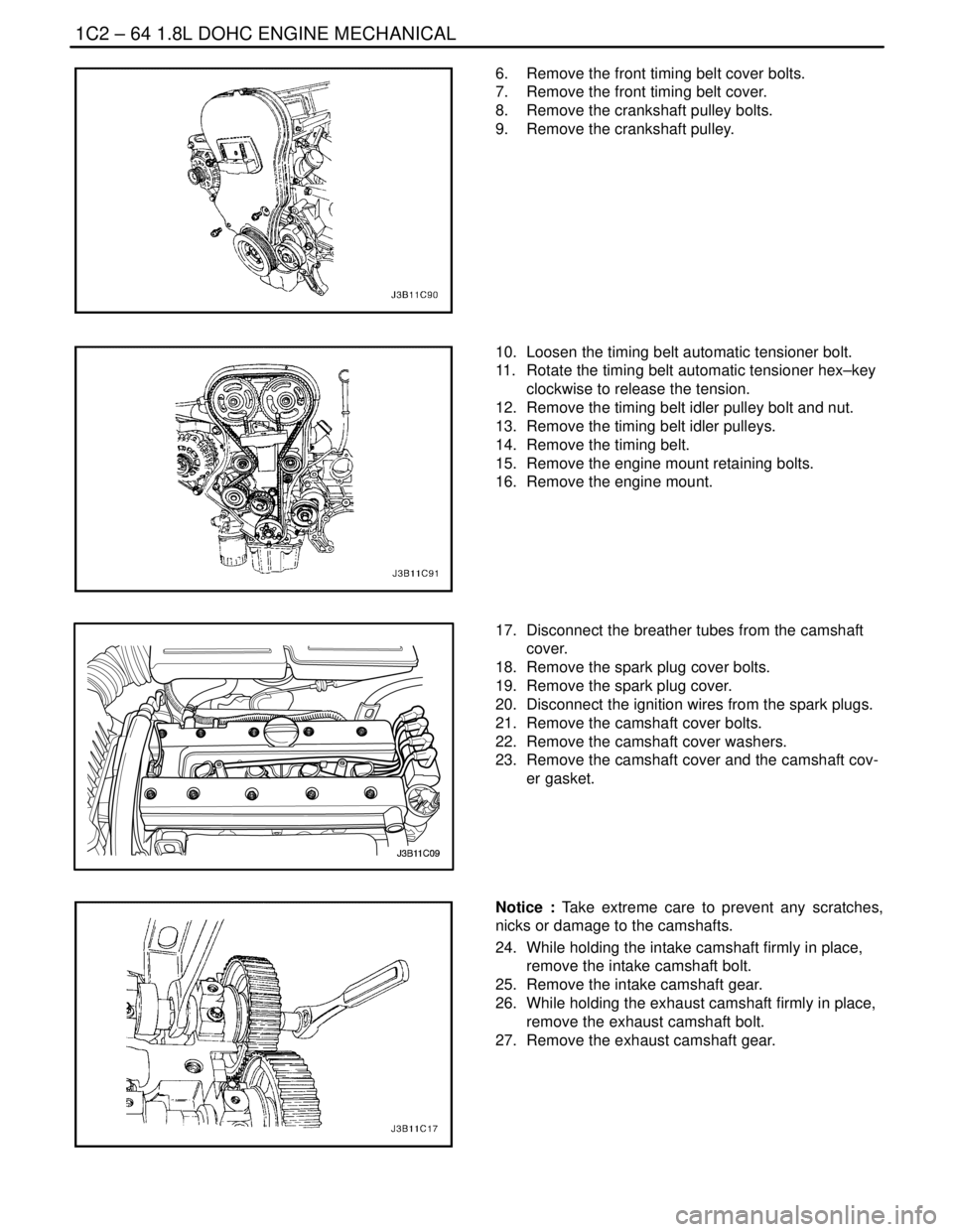
6. Remove the front timing belt cover bolts.
7. Remove the front timing belt cover.
8. Remove the crankshaft pulley bolts.
9. Remove the crankshaft pulley.
10. Loosen the timing belt automatic tensioner bolt.
11. Rotate the timing belt automatic tensioner hex–key
clockwise to release the tension.
12. Remove the timing belt idler pulley bolt and nut.
13. Remove the timing belt idler pulleys.
14. Remove the timing belt.
15. Remove the engine mount retaining bolts.
16. Remove the engine mount.
17. Disconnect the breather tubes from the camshaft
cover.
18. Remove the spark plug cover bolts.
19. Remove the spark plug cover.
20. Disconnect the ignition wires from the spark plugs.
21. Remove the camshaft cover bolts.
22. Remove the camshaft cover washers.
23. Remove the camshaft cover and the camshaft cov-
er gasket.
Notice : Take extreme care to prevent any scratches,
nicks or damage to the camshafts.
24. While holding the intake camshaft firmly in place,
remove the intake camshaft bolt.
25. Remove the intake camshaft gear.
26. While holding the exhaust camshaft firmly in place,
remove the exhaust camshaft bolt.
27. Remove the exhaust camshaft gear.
Page 188 of 2643
1C2 – 68I1.8L DOHC ENGINE MECHANICAL
DAEWOO V–121 BL4
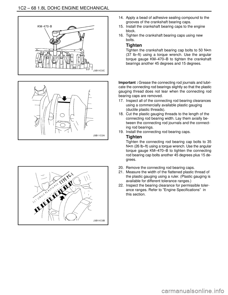
14. Apply a bead of adhesive sealing compound to the
grooves of the crankshaft bearing caps.
15. Install the crankshaft bearing caps to the engine
block.
16. Tighten the crankshaft bearing caps using new
bolts.
Tighten
Tighten the crankshaft bearing cap bolts to 50 NSm
(37 lb–ft) using a torque wrench. Use the angular
torque gauge KM–470–B to tighten the crankshaft
bearings another 45 degrees and 15 degrees.
Important : Grease the connecting rod journals and lubri-
cate the connecting rod bearings slightly so that the plastic
gauging thread does not tear when the connecting rod
bearing caps are removed.
17. Inspect all of the connecting rod bearing clearances
using a commercially available plastic gauging
(ductile plastic threads).
18. Cut the plastic gauging threads to the length of the
connecting rod bearing width. Lay them axially be-
tween the connecting rod journals and the connect-
ing rod bearings.
19. Install the connecting rod bearing caps.
Tighten
Tighten the connecting rod bearing cap bolts to 35
NSm (26 lb–ft) using a torque wrench. Use the angular
torque gauge KM–470–B to tighten the connecting
rod bearing cap bolts another 45 degrees plus 15 de-
grees.
20. Remove the connecting rod bearing caps.
21. Measure the width of the flattened plastic thread of
the plastic gauging using a ruler. (Plastic gauging is
available for different tolerance ranges.)
22. Inspect the bearing clearance for permissible toler-
ance ranges. Refer to ”Engine Specifications” in
this section.
Page 192 of 2643
1C2 – 72I1.8L DOHC ENGINE MECHANICAL
DAEWOO V–121 BL4
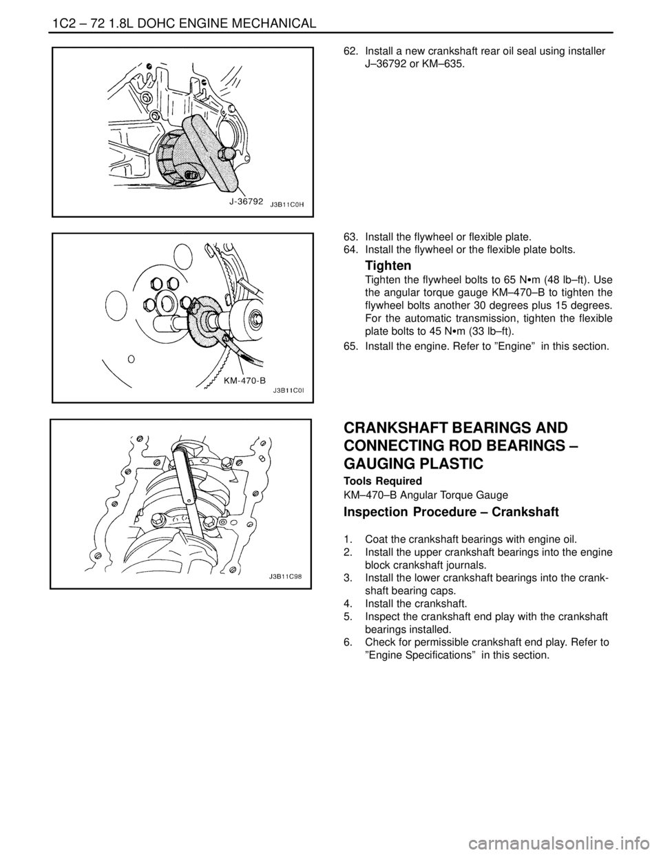
62. Install a new crankshaft rear oil seal using installer
J–36792 or KM–635.
63. Install the flywheel or flexible plate.
64. Install the flywheel or the flexible plate bolts.
Tighten
Tighten the flywheel bolts to 65 NSm (48 lb–ft). Use
the angular torque gauge KM–470–B to tighten the
flywheel bolts another 30 degrees plus 15 degrees.
For the automatic transmission, tighten the flexible
plate bolts to 45 NSm (33 lb–ft).
65. Install the engine. Refer to ”Engine” in this section.
CRANKSHAFT BEARINGS AND
CONNECTING ROD BEARINGS –
GAUGING PLASTIC
Tools Required
KM–470–B Angular Torque Gauge
Inspection Procedure – Crankshaft
1. Coat the crankshaft bearings with engine oil.
2. Install the upper crankshaft bearings into the engine
block crankshaft journals.
3. Install the lower crankshaft bearings into the crank-
shaft bearing caps.
4. Install the crankshaft.
5. Inspect the crankshaft end play with the crankshaft
bearings installed.
6. Check for permissible crankshaft end play. Refer to
”Engine Specifications” in this section.
Page 195 of 2643
1.8L DOHC ENGINE MECHANICAL 1C2 – 75
DAEWOO V–121 BL4
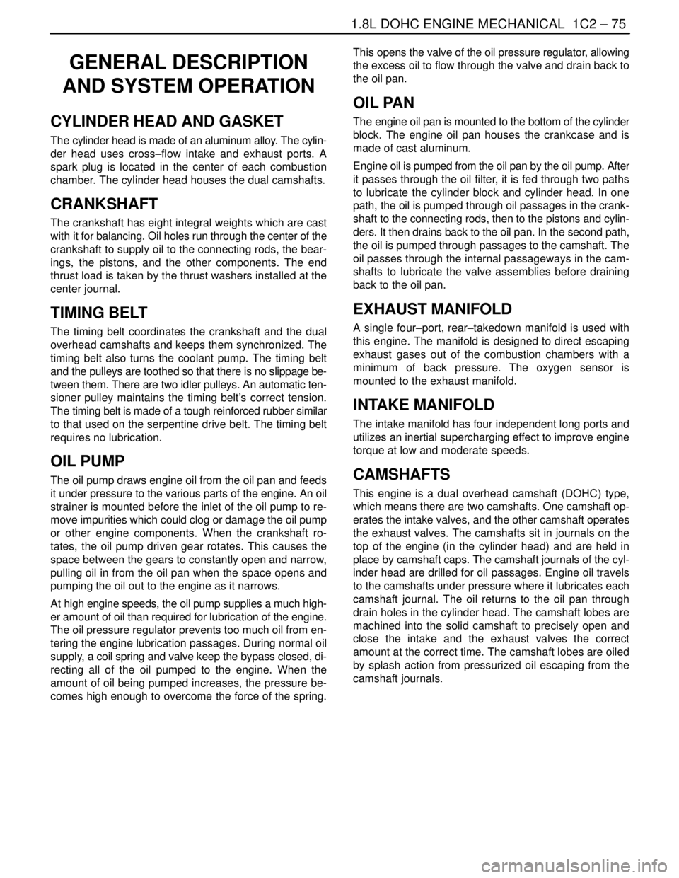
GENERAL DESCRIPTION
AND SYSTEM OPERATION
CYLINDER HEAD AND GASKET
The cylinder head is made of an aluminum alloy. The cylin-
der head uses cross–flow intake and exhaust ports. A
spark plug is located in the center of each combustion
chamber. The cylinder head houses the dual camshafts.
CRANKSHAFT
The crankshaft has eight integral weights which are cast
with it for balancing. Oil holes run through the center of the
crankshaft to supply oil to the connecting rods, the bear-
ings, the pistons, and the other components. The end
thrust load is taken by the thrust washers installed at the
center journal.
TIMING BELT
The timing belt coordinates the crankshaft and the dual
overhead camshafts and keeps them synchronized. The
timing belt also turns the coolant pump. The timing belt
and the pulleys are toothed so that there is no slippage be-
tween them. There are two idler pulleys. An automatic ten-
sioner pulley maintains the timing belt’s correct tension.
The timing belt is made of a tough reinforced rubber similar
to that used on the serpentine drive belt. The timing belt
requires no lubrication.
OIL PUMP
The oil pump draws engine oil from the oil pan and feeds
it under pressure to the various parts of the engine. An oil
strainer is mounted before the inlet of the oil pump to re-
move impurities which could clog or damage the oil pump
or other engine components. When the crankshaft ro-
tates, the oil pump driven gear rotates. This causes the
space between the gears to constantly open and narrow,
pulling oil in from the oil pan when the space opens and
pumping the oil out to the engine as it narrows.
At high engine speeds, the oil pump supplies a much high-
er amount of oil than required for lubrication of the engine.
The oil pressure regulator prevents too much oil from en-
tering the engine lubrication passages. During normal oil
supply, a coil spring and valve keep the bypass closed, di-
recting all of the oil pumped to the engine. When the
amount of oil being pumped increases, the pressure be-
comes high enough to overcome the force of the spring.This opens the valve of the oil pressure regulator, allowing
the excess oil to flow through the valve and drain back to
the oil pan.
OIL PAN
The engine oil pan is mounted to the bottom of the cylinder
block. The engine oil pan houses the crankcase and is
made of cast aluminum.
Engine oil is pumped from the oil pan by the oil pump. After
it passes through the oil filter, it is fed through two paths
to lubricate the cylinder block and cylinder head. In one
path, the oil is pumped through oil passages in the crank-
shaft to the connecting rods, then to the pistons and cylin-
ders. It then drains back to the oil pan. In the second path,
the oil is pumped through passages to the camshaft. The
oil passes through the internal passageways in the cam-
shafts to lubricate the valve assemblies before draining
back to the oil pan.
EXHAUST MANIFOLD
A single four–port, rear–takedown manifold is used with
this engine. The manifold is designed to direct escaping
exhaust gases out of the combustion chambers with a
minimum of back pressure. The oxygen sensor is
mounted to the exhaust manifold.
INTAKE MANIFOLD
The intake manifold has four independent long ports and
utilizes an inertial supercharging effect to improve engine
torque at low and moderate speeds.
CAMSHAFTS
This engine is a dual overhead camshaft (DOHC) type,
which means there are two camshafts. One camshaft op-
erates the intake valves, and the other camshaft operates
the exhaust valves. The camshafts sit in journals on the
top of the engine (in the cylinder head) and are held in
place by camshaft caps. The camshaft journals of the cyl-
inder head are drilled for oil passages. Engine oil travels
to the camshafts under pressure where it lubricates each
camshaft journal. The oil returns to the oil pan through
drain holes in the cylinder head. The camshaft lobes are
machined into the solid camshaft to precisely open and
close the intake and the exhaust valves the correct
amount at the correct time. The camshaft lobes are oiled
by splash action from pressurized oil escaping from the
camshaft journals.
Page 196 of 2643
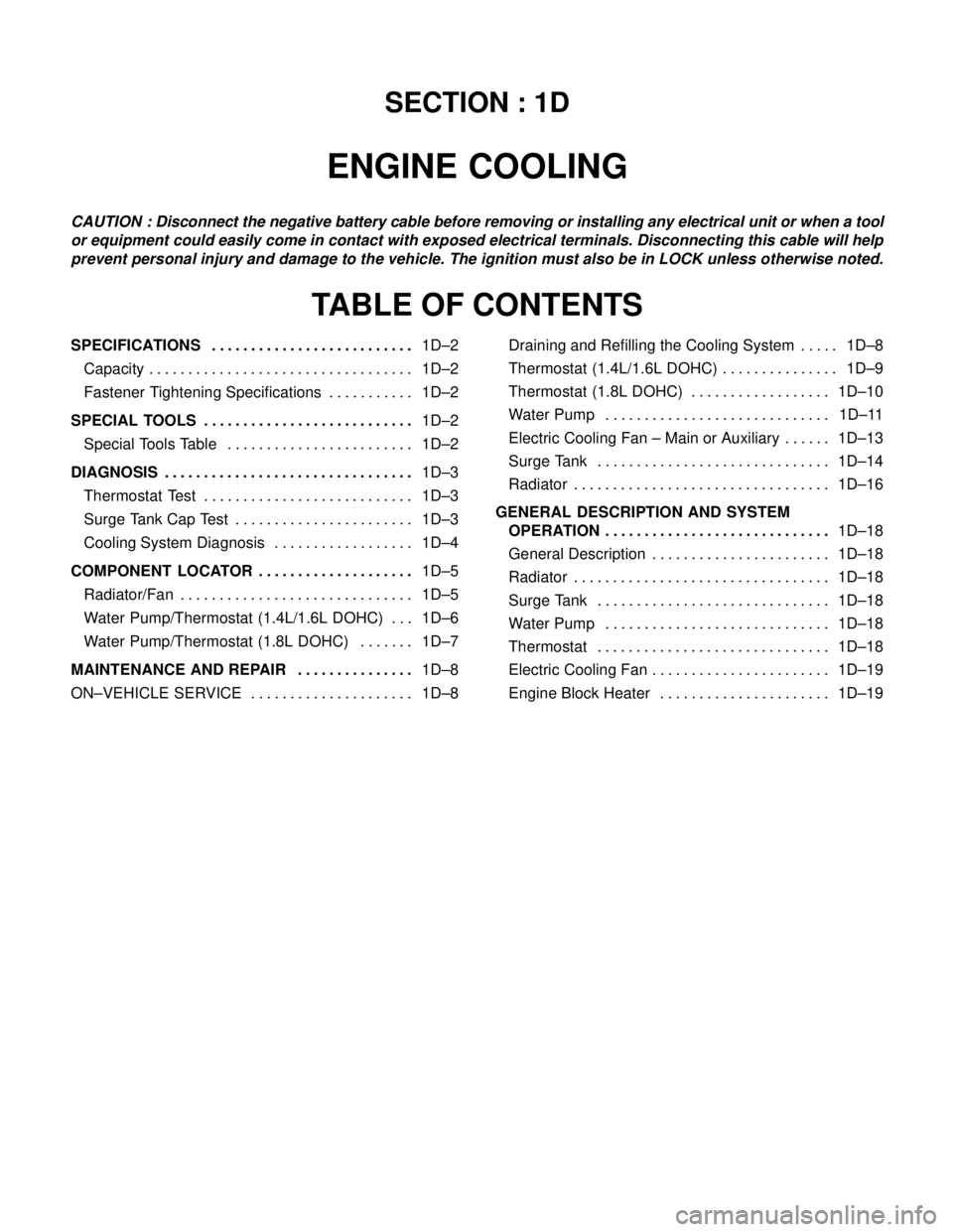
SECTION : 1D
ENGINE COOLING
CAUTION : Disconnect the negative battery cable before removing or installing any electrical unit or when a tool
or equipment could easily come in contact with exposed electrical terminals. Disconnecting this cable will help
prevent personal injury and damage to the vehicle. The ignition must also be in LOCK unless otherwise noted.
TABLE OF CONTENTS
SPECIFICATIONS1D–2 . . . . . . . . . . . . . . . . . . . . . . . . . .
Capacity 1D–2. . . . . . . . . . . . . . . . . . . . . . . . . . . . . . . . . .
Fastener Tightening Specifications 1D–2. . . . . . . . . . .
SPECIAL TOOLS1D–2 . . . . . . . . . . . . . . . . . . . . . . . . . . .
Special Tools Table 1D–2. . . . . . . . . . . . . . . . . . . . . . . .
DIAGNOSIS1D–3 . . . . . . . . . . . . . . . . . . . . . . . . . . . . . . . .
Thermostat Test 1D–3. . . . . . . . . . . . . . . . . . . . . . . . . . .
Surge Tank Cap Test 1D–3. . . . . . . . . . . . . . . . . . . . . . .
Cooling System Diagnosis 1D–4. . . . . . . . . . . . . . . . . .
COMPONENT LOCATOR1D–5 . . . . . . . . . . . . . . . . . . . .
Radiator/Fan 1D–5. . . . . . . . . . . . . . . . . . . . . . . . . . . . . .
Water Pump/Thermostat (1.4L/1.6L DOHC) 1D–6. . .
Water Pump/Thermostat (1.8L DOHC) 1D–7. . . . . . .
MAINTENANCE AND REPAIR1D–8 . . . . . . . . . . . . . . .
ON–VEHICLE SERVICE 1D–8. . . . . . . . . . . . . . . . . . . . . Draining and Refilling the Cooling System 1D–8. . . . .
Thermostat (1.4L/1.6L DOHC) 1D–9. . . . . . . . . . . . . . .
Thermostat (1.8L DOHC) 1D–10. . . . . . . . . . . . . . . . . .
Water Pump 1D–11. . . . . . . . . . . . . . . . . . . . . . . . . . . . .
Electric Cooling Fan – Main or Auxiliary 1D–13. . . . . .
Surge Tank 1D–14. . . . . . . . . . . . . . . . . . . . . . . . . . . . . .
Radiator 1D–16. . . . . . . . . . . . . . . . . . . . . . . . . . . . . . . . .
GENERAL DESCRIPTION AND SYSTEM
OPERATION1D–18 . . . . . . . . . . . . . . . . . . . . . . . . . . . . .
General Description 1D–18. . . . . . . . . . . . . . . . . . . . . . .
Radiator 1D–18. . . . . . . . . . . . . . . . . . . . . . . . . . . . . . . . .
Surge Tank 1D–18. . . . . . . . . . . . . . . . . . . . . . . . . . . . . .
Water Pump 1D–18. . . . . . . . . . . . . . . . . . . . . . . . . . . . .
Thermostat 1D–18. . . . . . . . . . . . . . . . . . . . . . . . . . . . . .
Electric Cooling Fan 1D–19. . . . . . . . . . . . . . . . . . . . . . .
Engine Block Heater 1D–19. . . . . . . . . . . . . . . . . . . . . .
Page 199 of 2643
1D – 4IENGINE COOLING
DAEWOO V–121 BL4
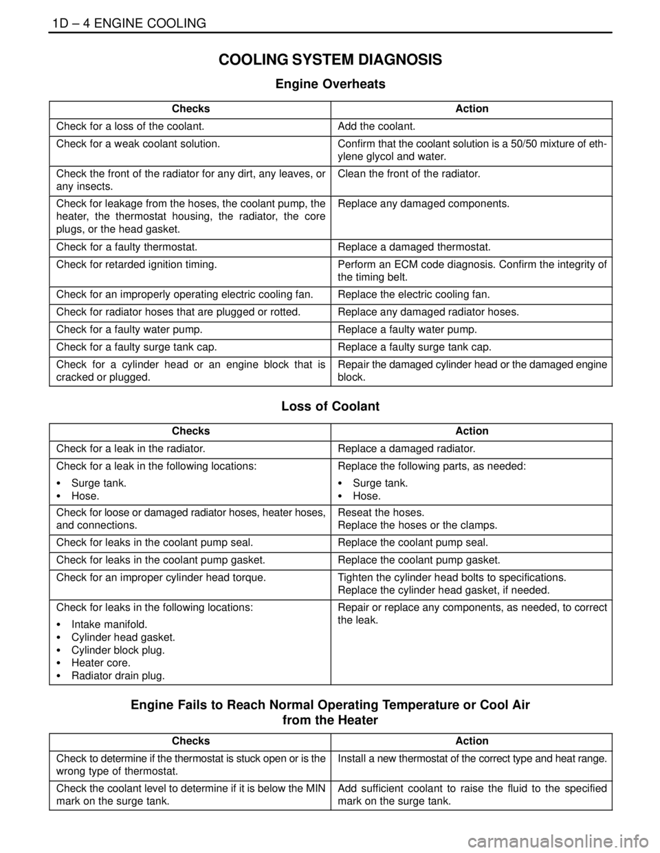
COOLING SYSTEM DIAGNOSIS
Engine Overheats
ChecksAction
Check for a loss of the coolant.Add the coolant.
Check for a weak coolant solution.Confirm that the coolant solution is a 50/50 mixture of eth-
ylene glycol and water.
Check the front of the radiator for any dirt, any leaves, or
any insects.Clean the front of the radiator.
Check for leakage from the hoses, the coolant pump, the
heater, the thermostat housing, the radiator, the core
plugs, or the head gasket.Replace any damaged components.
Check for a faulty thermostat.Replace a damaged thermostat.
Check for retarded ignition timing.Perform an ECM code diagnosis. Confirm the integrity of
the timing belt.
Check for an improperly operating electric cooling fan.Replace the electric cooling fan.
Check for radiator hoses that are plugged or rotted.Replace any damaged radiator hoses.
Check for a faulty water pump.Replace a faulty water pump.
Check for a faulty surge tank cap.Replace a faulty surge tank cap.
Check for a cylinder head or an engine block that is
cracked or plugged.Repair the damaged cylinder head or the damaged engine
block.
Loss of Coolant
ChecksAction
Check for a leak in the radiator.Replace a damaged radiator.
Check for a leak in the following locations:
S Surge tank.
S Hose.Replace the following parts, as needed:
S Surge tank.
S Hose.
Check for loose or damaged radiator hoses, heater hoses,
and connections.Reseat the hoses.
Replace the hoses or the clamps.
Check for leaks in the coolant pump seal.Replace the coolant pump seal.
Check for leaks in the coolant pump gasket.Replace the coolant pump gasket.
Check for an improper cylinder head torque.Tighten the cylinder head bolts to specifications.
Replace the cylinder head gasket, if needed.
Check for leaks in the following locations:
S Intake manifold.
S Cylinder head gasket.
S Cylinder block plug.
S Heater core.
S Radiator drain plug.Repair or replace any components, as needed, to correct
the leak.
Engine Fails to Reach Normal Operating Temperature or Cool Air
from the Heater
ChecksAction
Check to determine if the thermostat is stuck open or is the
wrong type of thermostat.Install a new thermostat of the correct type and heat range.
Check the coolant level to determine if it is below the MIN
mark on the surge tank.Add sufficient coolant to raise the fluid to the specified
mark on the surge tank.