2004 DAEWOO NUBIRA lock
[x] Cancel search: lockPage 220 of 2643

1E – 6IENGINE ELECTRICAL
DAEWOO V–121 BL4
DIAGNOSIS
NO CRANK
StepActionValue(s)YesNo
11. Turn the headlamps ON.
2. Turn the dome lamps ON.
3. Turn the ignition to START.
Did the lights dim or go out?–Go to Step 2Go to Step 8
2Check the battery state of charge.
Is the green eye showing from the built–in hydrome-
ter?–Go to Step 3Go to
”Charging Pro-
cedure”
31. Connect the voltmeter positive lead to the posi-
tive battery terminal.
2. Connect the voltmeter negative lead to the
negative battery terminal.
3. Turn the ignition to START.
Does the voltmeter indicate the value specified?< 9.6 vGo to
”Charging Pro-
cedure”Go to Step 4
41. Connect the voltmeter negative lead to the
negative battery terminal.
2. Connect the positive voltmeter lead to the en-
gine block.
Does the voltmeter indicate the value specified?> 0.5 vGo to Step 5Go to Step 6
5Clean, tighten, or replace the negative battery cable.
Is the repair complete?–System OK–
61. Connect the voltmeter positive lead to the start-
er ”B+” terminal.
2. Connect the voltmeter negative lead to the
negative battery terminal.
Does the voltmeter indicate the value specified?< 9 vGo to Step 7Go to Step 13
7Clean, tighten, or replace the positive battery cable.
Is the repair complete?–System OK–
8Inspect the engine fuse block fuse Ef5.
Is the fuse OK?–Go to Step 10Go to Step 9
9Inspect the engine fuse block fuse Ef4.
Is the fuse OK?–System OK–
10Check the connection at the starter ”ST” terminal.
Is the connection OK?–Go to Step 12Go to Step 11
11Clean or tighten the connection as needed.
Is the repair complete?–System OK–
121. Connect the voltmeter positive lead to the start-
er ”ST” terminal.
2. Connect the voltmeter negative lead to the
negative battery terminal.
3. Turn the ignition to START.
Does the voltmeter indicate the value specified?< 7 vGo to Step 13Go to Step 14
13Repair or replace the starter as needed.
Is the repair complete?–System OK–
14Determine the type of transaxle on the vehicle.
Is the vehicle equipped with an automatic transaxle?–Go to Step 15Go to Step 32
Page 221 of 2643

ENGINE ELECTRICAL 1E – 7
DAEWOO V–121 BL4
StepNo Yes Value(s) Action
151. Disconnect the neutral safety back–up (PNP)
switch.
2. Connect the negative voltmeter lead to the
PNP switch connector terminal E.
3. Connect the positive voltmeter lead to battery
positive.
Does the voltmeter indicate the value specified?11–14 vGo to Step 16Go to Step 19
161. Jumper the PNP switch connector terminals 9
and 10.
2. Connect the negative voltmeter lead to the igni-
tion switch.
3. Connect the positive voltmeter lead to battery
positive.
Does the voltmeter indicate the value specified?11–14 vGo to Step 17Go to Step 18
17Replace the neutral safety backup switch.
Is the repair complete?–System OK–
18Repair the wire as needed.
Is the repair complete?–System OK–
19Repair the open wire between the PNP switch con-
nector terminal E and ground.
Is the repair complete?–System OK–
201. Connect the voltmeter positive lead to the igni-
tion switch connector terminal 3 by backprob-
ing the connector.
2. Connect the voltmeter negative lead to ground.
Does the voltmeter indicate the value specified?11–14 vGo to Step 22Go to Step 21
21Repair the open in the wiring between the engine
block fuse Ef5 and the ignition switch connector ter-
minal 2.
Is the repair complete?–System OK–
221. Connect the voltmeter positive lead to the igni-
tion switch connector terminal 3 by backprob-
ing the connector.
2. Connect the voltmeter negative lead to ground.
3. Turn the ignition to START.
Does the voltmeter indicate the value specified?11–14 vGo to Step 23Go to Step 27
231. Connect the voltmeter positive lead to the igni-
tion switch connector terminal 3 by backprob-
ing the connector.
2. Connect the voltmeter negative lead to ground.
Does the voltmeter indicate the value specified?11–14 vGo to Step 25Go to Step 24
24Repair the open in the wiring between the engine
block fuse Ef5 and the ignition switch connector ter-
minal 3.
Is the repair complete?–System OK–
251. Connect the voltmeter positive lead to the igni-
tion switch connector terminal 3 by backprob-
ing the connector.
2. Connect the voltmeter negative lead to ground.
3. Turn the ignition to START.
Does the voltmeter indicate the value specified?11–14 vGo to Step 26Go to Step 27
Page 225 of 2643

ENGINE ELECTRICAL 1E – 11
DAEWOO V–121 BL4
MAINTENANCE AND REPAIR
ON–VEHICLE SERVICE
GENERATOR
Removal Procedure
1. Disconnect the negative battery cable.
2. Disconnect the manifold air temperature (MAT)
sensor electrical connector the air intake tube.
3. Remove all the clamps from the air cleaner outlet
hose, and set aside the tube.
4. Raise and suitably support the vehicle.
5. Disconnect the harness connector from the back of
the generator, and the generator lead to the battery.
6. Remove the serpentine accessory drive belt by low-
ering the vehicle and turning the automatic tension-
er roller bolt clockwise to relieve tension on the belt.
Refer to Section 6B, Power Steering Pump.
7. Push up the power steering reservoir and set it
aside.
8. Remove the bolt of the generator upper engine con-
necting bracket to the 1.4L/1.6L engine.
Page 227 of 2643

ENGINE ELECTRICAL 1E – 13
DAEWOO V–121 BL4
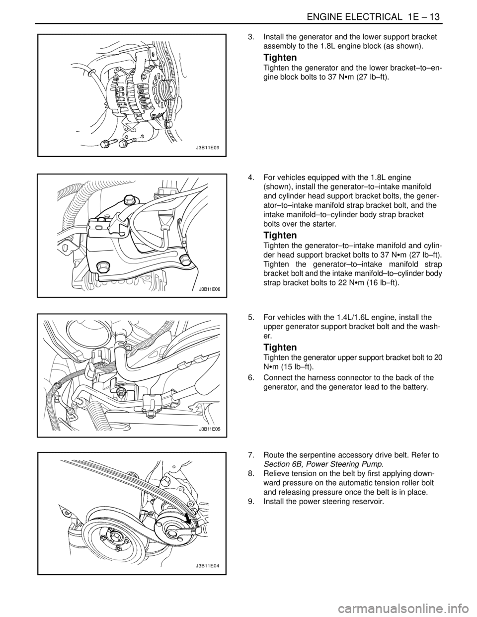
3. Install the generator and the lower support bracket
assembly to the 1.8L engine block (as shown).
Tighten
Tighten the generator and the lower bracket–to–en-
gine block bolts to 37 NSm (27 lb–ft).
4. For vehicles equipped with the 1.8L engine
(shown), install the generator–to–intake manifold
and cylinder head support bracket bolts, the gener-
ator–to–intake manifold strap bracket bolt, and the
intake manifold–to–cylinder body strap bracket
bolts over the starter.
Tighten
Tighten the generator–to–intake manifold and cylin-
der head support bracket bolts to 37 NSm (27 lb–ft).
Tighten the generator–to–intake manifold strap
bracket bolt and the intake manifold–to–cylinder body
strap bracket bolts to 22 NSm (16 lb–ft).
5. For vehicles with the 1.4L/1.6L engine, install the
upper generator support bracket bolt and the wash-
er.
Tighten
Tighten the generator upper support bracket bolt to 20
NSm (15 lb–ft).
6. Connect the harness connector to the back of the
generator, and the generator lead to the battery.
7. Route the serpentine accessory drive belt. Refer to
Section 6B, Power Steering Pump.
8. Relieve tension on the belt by first applying down-
ward pressure on the automatic tension roller bolt
and releasing pressure once the belt is in place.
9. Install the power steering reservoir.
Page 228 of 2643

1E – 14IENGINE ELECTRICAL
DAEWOO V–121 BL4
10. Install the air cleaner outlet hose and connect the
MAT electrical connector.
11. Connect the negative battery cable.
STARTER
Removal Procedure
1. Remove the nut which secures the starter ground
wire to the lower mounting stud and remove the
ground wire.
2. Remove the lower starter stud/weld nut assembly
(1.4L/1.6L engine).
3. For vehicles equipped with the 1.8L engine, remove
the starter–to–engine block mounting bolt and the
starter–to–transmission mounting bolt.
4. Remove the starter solenoid nuts to disconnect the
electrical cable.
5. Remove the starter assembly.
Installation Procedure
1. Place the starter assembly in position using an as-
sistant to prop up the starter to aid in screwing in
the upper stud with the weld nut.
2. Install the upper and the lower starter mounting
bolts.
Tighten
Tighten the starter mounting studs to 23 NSm (16 lb
ft).
3. Install the starter mounting bolts (1.8L engine).
Tighten
Tighten the starter–to–engine block mounting bolt to
45 NSm (33 lb–ft) and the starter–to–engine transaxle
mounting bolt to 50 NSm (37 lb–ft).
Page 235 of 2643

ENGINE ELECTRICAL 1E – 21
DAEWOO V–121 BL4
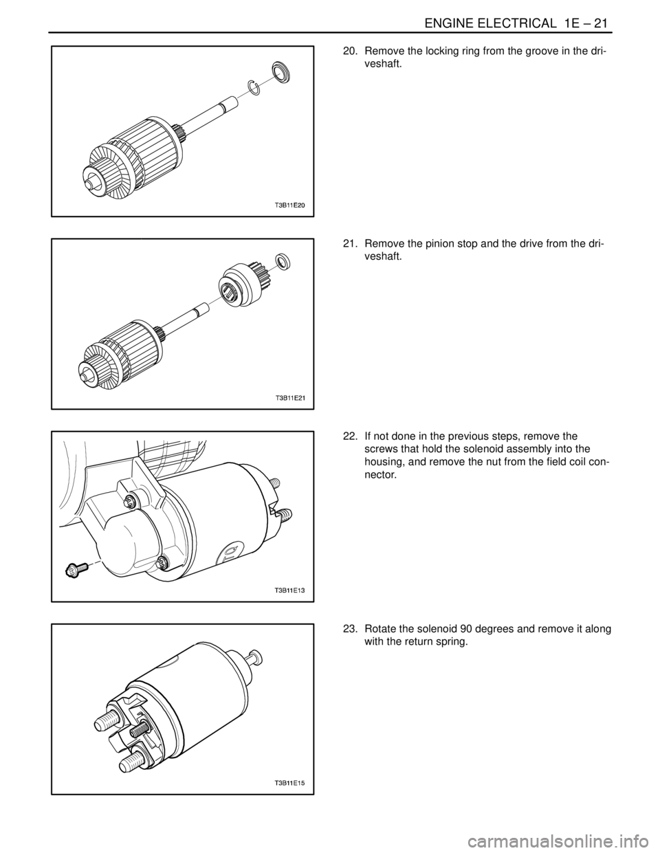
20. Remove the locking ring from the groove in the dri-
veshaft.
21. Remove the pinion stop and the drive from the dri-
veshaft.
22. If not done in the previous steps, remove the
screws that hold the solenoid assembly into the
housing, and remove the nut from the field coil con-
nector.
23. Rotate the solenoid 90 degrees and remove it along
with the return spring.
Page 237 of 2643

ENGINE ELECTRICAL 1E – 23
DAEWOO V–121 BL4
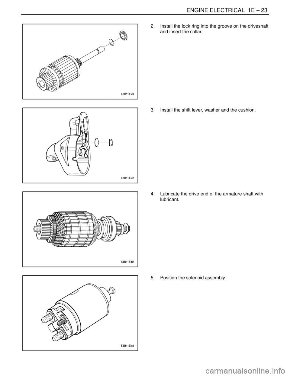
2. Install the lock ring into the groove on the driveshaft
and insert the collar.
3. Install the shift lever, washer and the cushion.
4. Lubricate the drive end of the armature shaft with
lubricant.
5. Position the solenoid assembly.
Page 247 of 2643

SECTION : 1F
ENGINE CONTROLS
CAUTION : Disconnect the negative battery cable before removing or installing any electrical unit o r w hen a
tool or equipment could easily come in contact with exposed electrical terminals. Disconnecting this cable will
help prevent personal injury and damage to the vehicle. The ignition must also be in LOCK unless otherwise
noted.
TABLE OF CONTENTS
SPECIFICATIONS1F–6 . . . . . . . . . . . . . . . . . . . . . . . . . .
Engine Data Display Tables 1F–6. . . . . . . . . . . . . . . . .
Engine Data Display Table Definitions 1F–7. . . . . . . .
Fastener Tightening Specifications 1F–10. . . . . . . . .
Fuel System Specifications 1F–11. . . . . . . . . . . . . . . . .
Temperature Vs Resistance 1F–11. . . . . . . . . . . . . . . .
SCHEMATIC AND ROUTING DIAGRAMS1F–12 . . . .
ECM Wiring Diagram
(1.4L/1.6L DOHC – 1 OF 6) 1F–12. . . . . . . . . . . . . .
ECM Wiring Diagram
(1.4L/1.6L DOHC – 2 OF 6) 1F–13. . . . . . . . . . . . . .
ECM Wiring Diagram
(1.4L/1.6L DOHC – 3 OF 6) 1F–14. . . . . . . . . . . . . .
ECM Wiring Diagram
(1.4L/1.6L DOHC – 4 OF 6) 1F–15. . . . . . . . . . . . . .
ECM Wiring Diagram
(1.4L/1.6L DOHC – 5 OF 6) 1F–16. . . . . . . . . . . . . .
ECM Wiring Diagram
(1.4L/1.6L DOHC – 6 OF 6) 1F–17. . . . . . . . . . . . . .
ECM Wiring Diagram (1.8L DOHC – 1 OF 6) 1F–18.
ECM Wiring Diagram (1.8L DOHC – 2 OF 6) 1F–19.
ECM Wiring Diagram (1.8L DOHC – 3 OF 6) 1F–20.
ECM Wiring Diagram (1.8L DOHC – 4 OF 6) 1F–21.
ECM Wiring Diagram (1.8L DOHC – 5 OF 6) 1F–22.
ECM Wiring Diagram (1.8L DOHC – 6 OF 6) 1F–23.
Connector End View 1F–24. . . . . . . . . . . . . . . . . . . . . .
COMPONENT LOCATOR1F–28 . . . . . . . . . . . . . . . . . . .
Component Locator (1.4L/1.6L DOHC) 1F–28. . . . . .
Component Locator (1.8L DOHC) 1F–29. . . . . . . . . . .
DIAGNOSIS1F–30 . . . . . . . . . . . . . . . . . . . . . . . . . . . . . . .
SYSTEM DIAGNOSIS 1F–30. . . . . . . . . . . . . . . . . . . . . .
Diagnostic Aids 1F–30. . . . . . . . . . . . . . . . . . . . . . . . . . .
Idle Learn Procedure 1F–30. . . . . . . . . . . . . . . . . . . . . .
TEC (Tooth Error Correction) Learn Procedure 1F–31ON–Board Diagnostic (EOBD) System Check
(1.4L/1.6L DOHC) 1F–32. . . . . . . . . . . . . . . . . . . . . . .
ON–Board Diagnostic (EOBD) System Check
(1.8L DOHC) 1F–34. . . . . . . . . . . . . . . . . . . . . . . . . . .
Multiple ECM Informationn Sensor Dtcs Set 1F–36. .
Engine Cranks But Will Not Run
(1.4L/1.6L DOHC) 1F–40. . . . . . . . . . . . . . . . . . . . . . .
Engine Cranks But Will Not Run (1.8L DOHC) 1F–47
No Malfunction Indicator Lamp (
1.4L/1.6L DOHC) 1F–54. . . . . . . . . . . . . . . . . . . . . . .
No Malfunction Indicator Lamp (1.8L DOHC) 1F–56.
Malfunction Indicator Lamp On Steady (1.4L/1.6L
DOHC) 1F–58. . . . . . . . . . . . . . . . . . . . . . . . . . . . . . . .
Malfunction Indicator Lamp On Steady
(1.8L DOHC) 1F–60. . . . . . . . . . . . . . . . . . . . . . . . . . .
Fuel System Diagnosis 1F–62. . . . . . . . . . . . . . . . . . . .
Fuel Pump Relay Circuit Check
(1.4L/1.6L DOHC) 1F–65. . . . . . . . . . . . . . . . . . . . . . .
Fuel Pump Relay Circuit Check (1.8L DOHC) 1F–68.
Main Relay Circuit Check (1.4L/1.6L DOHC) 1F–71.
Main Relay Circuit Check (1.8L DOHC) 1F–73. . . . . .
Manifold Absolute Pressure Check
(1.4L/1.6L DOHC) 1F–75. . . . . . . . . . . . . . . . . . . . . . .
Manifold Absolute Pressure Check
(1.8L DOHC) 1F–77. . . . . . . . . . . . . . . . . . . . . . . . . . .
Idle Air Control System Check
(1.4L/1.6L DOHC) 1F–79. . . . . . . . . . . . . . . . . . . . . . .
Idle Air Control System Check (1.8L DOHC) 1F–82. .
Ignition System Check (1.4L/1.6L DOHC) 1F–85. . . .
Ignition System Check (1.8L DOHC) 1F–88. . . . . . . .
Engine Cooling Fan Circuit Check – Dual Fan
(1.4L/1.6L DOHC) 1F–93. . . . . . . . . . . . . . . . . . . . . . .
Engine Cooling Fan Circuit Check – Dual Fan
(1.8L DOHC) 1F–100. . . . . . . . . . . . . . . . . . . . . . . . . .
Data Link Connector Diagnosis
(1.4L/1.6L DOHC) 1F–106. . . . . . . . . . . . . . . . . . . . . .
Data Link Connector Diagnosis (1.8L DOHC) 1F–108
Fuel Injector Balance Test 1F–110. . . . . . . . . . . . . . . .