Page 153 of 2643
1.8L DOHC ENGINE MECHANICAL 1C2 – 33
DAEWOO V–121 BL4
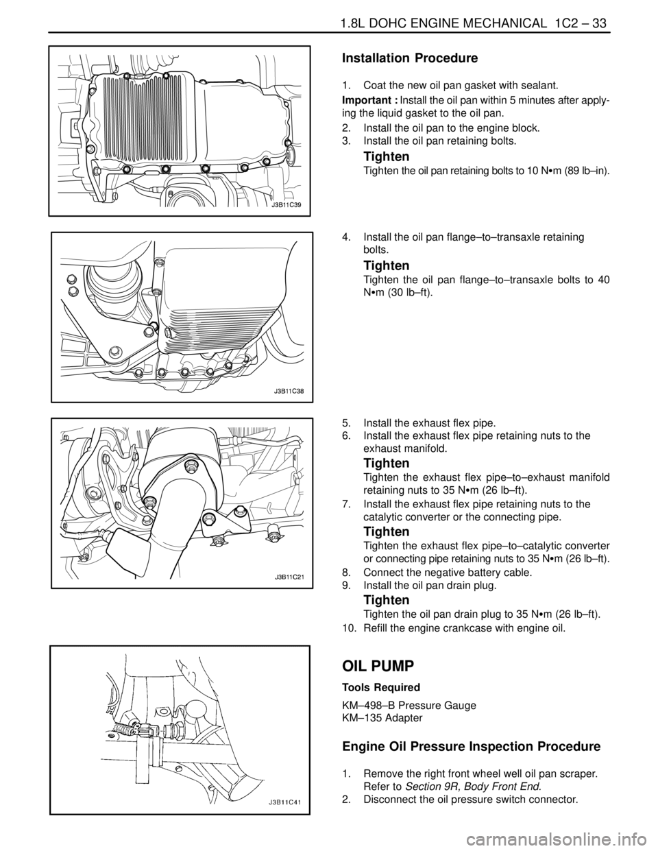
Installation Procedure
1. Coat the new oil pan gasket with sealant.
Important : Install the oil pan within 5 minutes after apply-
ing the liquid gasket to the oil pan.
2. Install the oil pan to the engine block.
3. Install the oil pan retaining bolts.
Tighten
Tighten the oil pan retaining bolts to 10 NSm (89 lb–in).
4. Install the oil pan flange–to–transaxle retaining
bolts.
Tighten
Tighten the oil pan flange–to–transaxle bolts to 40
NSm (30 lb–ft).
5. Install the exhaust flex pipe.
6. Install the exhaust flex pipe retaining nuts to the
exhaust manifold.
Tighten
Tighten the exhaust flex pipe–to–exhaust manifold
retaining nuts to 35 NSm (26 lb–ft).
7. Install the exhaust flex pipe retaining nuts to the
catalytic converter or the connecting pipe.
Tighten
Tighten the exhaust flex pipe–to–catalytic converter
or connecting pipe retaining nuts to 35 NSm (26 lb–ft).
8. Connect the negative battery cable.
9. Install the oil pan drain plug.
Tighten
Tighten the oil pan drain plug to 35 NSm (26 lb–ft).
10. Refill the engine crankcase with engine oil.
OIL PUMP
Tools Required
KM–498–B Pressure Gauge
KM–135 Adapter
Engine Oil Pressure Inspection Procedure
1. Remove the right front wheel well oil pan scraper.
Refer to Section 9R, Body Front End.
2. Disconnect the oil pressure switch connector.
Page 155 of 2643
1.8L DOHC ENGINE MECHANICAL 1C2 – 35
DAEWOO V–121 BL4
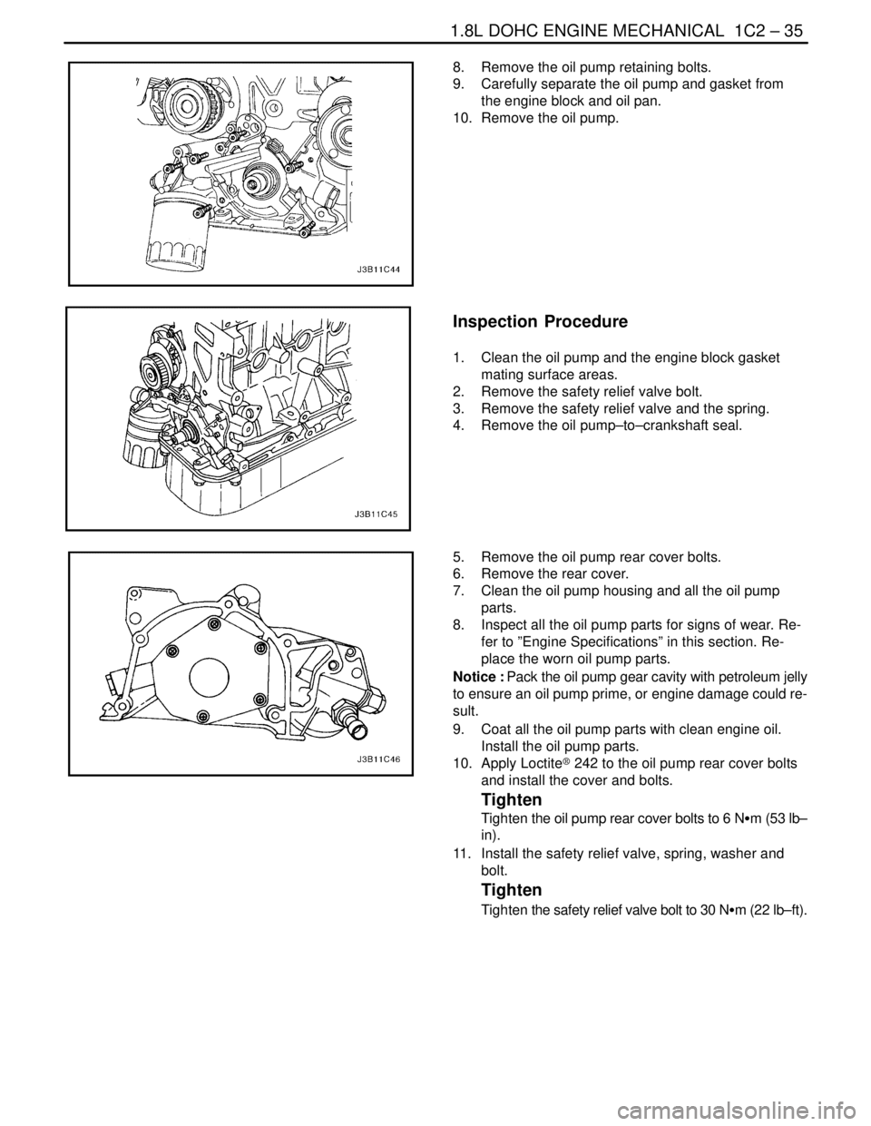
8. Remove the oil pump retaining bolts.
9. Carefully separate the oil pump and gasket from
the engine block and oil pan.
10. Remove the oil pump.
Inspection Procedure
1. Clean the oil pump and the engine block gasket
mating surface areas.
2. Remove the safety relief valve bolt.
3. Remove the safety relief valve and the spring.
4. Remove the oil pump–to–crankshaft seal.
5. Remove the oil pump rear cover bolts.
6. Remove the rear cover.
7. Clean the oil pump housing and all the oil pump
parts.
8. Inspect all the oil pump parts for signs of wear. Re-
fer to ”Engine Specifications” in this section. Re-
place the worn oil pump parts.
Notice : Pack the oil pump gear cavity with petroleum jelly
to ensure an oil pump prime, or engine damage could re-
sult.
9. Coat all the oil pump parts with clean engine oil.
Install the oil pump parts.
10. Apply Loctite® 242 to the oil pump rear cover bolts
and install the cover and bolts.
Tighten
Tighten the oil pump rear cover bolts to 6 NSm (53 lb–
in).
11. Install the safety relief valve, spring, washer and
bolt.
Tighten
Tighten the safety relief valve bolt to 30 NSm (22 lb–ft).
Page 156 of 2643
1C2 – 36I1.8L DOHC ENGINE MECHANICAL
DAEWOO V–121 BL4
Installation Procedure
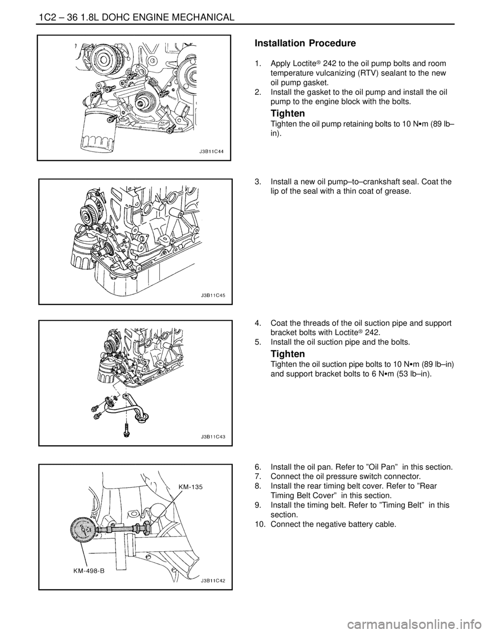
1. Apply Loctite® 242 to the oil pump bolts and room
temperature vulcanizing (RTV) sealant to the new
oil pump gasket.
2. Install the gasket to the oil pump and install the oil
pump to the engine block with the bolts.
Tighten
Tighten the oil pump retaining bolts to 10 NSm (89 lb–
in).
3. Install a new oil pump–to–crankshaft seal. Coat the
lip of the seal with a thin coat of grease.
4. Coat the threads of the oil suction pipe and support
bracket bolts with Loctite® 242.
5. Install the oil suction pipe and the bolts.
Tighten
Tighten the oil suction pipe bolts to 10 NSm (89 lb–in)
and support bracket bolts to 6 NSm (53 lb–in).
6. Install the oil pan. Refer to ”Oil Pan” in this section.
7. Connect the oil pressure switch connector.
8. Install the rear timing belt cover. Refer to ”Rear
Timing Belt Cover” in this section.
9. Install the timing belt. Refer to ”Timing Belt” in this
section.
10. Connect the negative battery cable.
Page 158 of 2643

1C2 – 38I1.8L DOHC ENGINE MECHANICAL
DAEWOO V–121 BL4
3. Install the timing belt idler pulleys.
4. Install the timing belt idler pulley bolt and nut.
Tighten
Tighten the timing belt idler pulley bolt and nut to 25
NSm (18 lb–ft).
5. Tension the timing belt by turning the timing belt
automatic tensioner hex–key tab counterclockwise
until the pointer is aligned to the indicator.
Tighten
Tighten the timing belt automatic tensioner bolt to 25
NSm (18 lb–ft).
6. Install the front timing belt cover.
7. Install the front timing belt cover bolts.
Tighten
Tighten the front timing belt cover bolts to 6 NSm (53
lb–in).
8. Install the engine mount bracket and retaining bolts.
Tighten
Tighten the engine mount bracket retaining bolts to 55
NSm (41 lb–ft).
9. Remove the engine assembly support fixture
J–28467–B, and the channel X–28467–560.
10. Install the serpentine accessory drive belt. Refer to
Section 6B, Power Steering Pump.
11. Connect the negative battery cable.
INTAKE MANIFOLD
Removal Procedure
1. Remove the fuel pump fuse.
2. Start the engine. After it stalls, crank the engine for
10 seconds to rid the fuel system of fuel pressure.
3. Disconnect the negative battery cable.
4. Disconnect the charcoal canister purge (CCP) and
exhaust gas recirculation (EGR) solenoid from the
intake manifold and loosen the bracket bolt.
5. Drain the engine coolant. Refer to Section 1D, En-
gine Cooling.
6. Disconnect the manifold air temperature sensor
(MAT) connector.
7. Disconnect the air cleaner outlet hose from the
throttle body.
Page 159 of 2643

1.8L DOHC ENGINE MECHANICAL 1C2 – 39
DAEWOO V–121 BL4
8. Disconnect the idle air control (IAC) valve connec-
tor.
9. Disconnect the throttle position sensor (TPS) con-
nector.
10. Disconnect the manifold absolute pressure (MAP)
sensor connector.
11. Disconnect the coolant hoses at the throttle body.
12. Disconnect all of the necessary vacuum hoses, in-
cluding the vacuum hose at the fuel pressure regu-
lator and the brake booster vacuum hose at the
intake manifold.
13. Disconnect the throttle cable from the throttle body
and the intake manifold.
14. Remove the throttle cable bracket bolts from the
intake manifold.
15. Remove the throttle cable bracket.
16. Remove the generator–to–intake manifold strap
bracket bolts and strap.
17. Remove the fuel rail as an assembly. Refer to Sec-
tion 1F, Engine Controls.
18. Remove the generator–to–intake manifold support
bracket bolts.
19. Remove the generator–to–intake manifold support
bracket.
20. Remove the intake manifold support bracket bolt at
the engine block and the intake manifold.
21. Remove the intake manifold support bracket.
22. Remove the intake manifold retaining bolt and nuts
in the sequence shown.
23. Remove the intake manifold.
24. Remove the intake manifold gasket.
25. Clean the sealing surfaces of the intake manifold
and the cylinder head.
Page 160 of 2643
1C2 – 40I1.8L DOHC ENGINE MECHANICAL
DAEWOO V–121 BL4
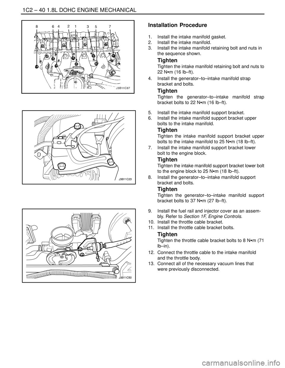
Installation Procedure
1. Install the intake manifold gasket.
2. Install the intake manifold.
3. Install the intake manifold retaining bolt and nuts in
the sequence shown.
Tighten
Tighten the intake manifold retaining bolt and nuts to
22 NSm (16 lb–ft).
4. Install the generator–to–intake manifold strap
bracket and bolts.
Tighten
Tighten the generator–to–intake manifold strap
bracket bolts to 22 NSm (16 lb–ft).
5. Install the intake manifold support bracket.
6. Install the intake manifold support bracket upper
bolts to the intake manifold.
Tighten
Tighten the intake manifold support bracket upper
bolts to the intake manifold to 25 NSm (18 lb–ft).
7. Install the intake manifold support bracket lower
bolt to the engine block.
Tighten
Tighten the intake manifold support bracket lower bolt
to the engine block to 25 NSm (18 lb–ft).
8. Install the generator–to–intake manifold support
bracket and bolts.
Tighten
Tighten the generator–to–intake manifold support
bracket bolts to 37 NSm (27 lb–ft).
9. Install the fuel rail and injector cover as an assem-
bly. Refer to Section 1F, Engine Controls.
10. Install the throttle cable bracket.
11. Install the throttle cable bracket bolts.
Tighten
Tighten the throttle cable bracket bolts to 8 NSm (71
lb–in).
12. Connect the throttle cable to the intake manifold
and the throttle body.
13. Connect all of the necessary vacuum lines that
were previously disconnected.
Page 168 of 2643

1C2 – 48I1.8L DOHC ENGINE MECHANICAL
DAEWOO V–121 BL4
40. Remove the crankshaft pulley bolts.
41. Remove the crankshaft pulley.
42. Disconnect the vacuum lines at the charcoal canis-
ter purge solenoid.
43. Disconnect the electrical connector at the charcoal
canister purge (CCP) and the exhaust gas recir-
culation (EGR) solenoid.
44. Disconnect the electrical connector at the oil pres-
sure switch.
45. Disconnect the crankshaft position sensor (CPS)
connector.
46. Disconnect the knock sensor connector.
47. Remove the transaxle torque converter bolts, if au-
tomatic transaxle equipped.
48. Remove the transaxle bell housing bolts and the oil
pan flange bolts.
49. Support the transaxle with a floor jack.
50. Install the engine lifting device.
51. Disconnect the right engine mount bracket from the
engine mount by removing the retaining bolt.
52. Remove the right engine mount bracket from the
engine block and frame mount. Refer to Section
5B, Five Speed Manual Transaxle, or Section 5A,
Automatic Transaxle.
53. Separate the engine block from the transaxle. Re-
move the engine.
Installation Procedure
1. Install the engine into the engine compartment.
2. Align the engine alignment pins to the transaxle.
3. Install the transaxle bell housing bolts.
Tighten
Tighten the transaxle bell housing bolts to 75 NSm (55
lb–ft).
4. Install the oil pan flange–to–transaxle bolts.
Tighten
Tighten the oil pan flange–to–transaxle bolts to 40
NSm (30 lb–ft).
Page 169 of 2643
1.8L DOHC ENGINE MECHANICAL 1C2 – 49
DAEWOO V–121 BL4
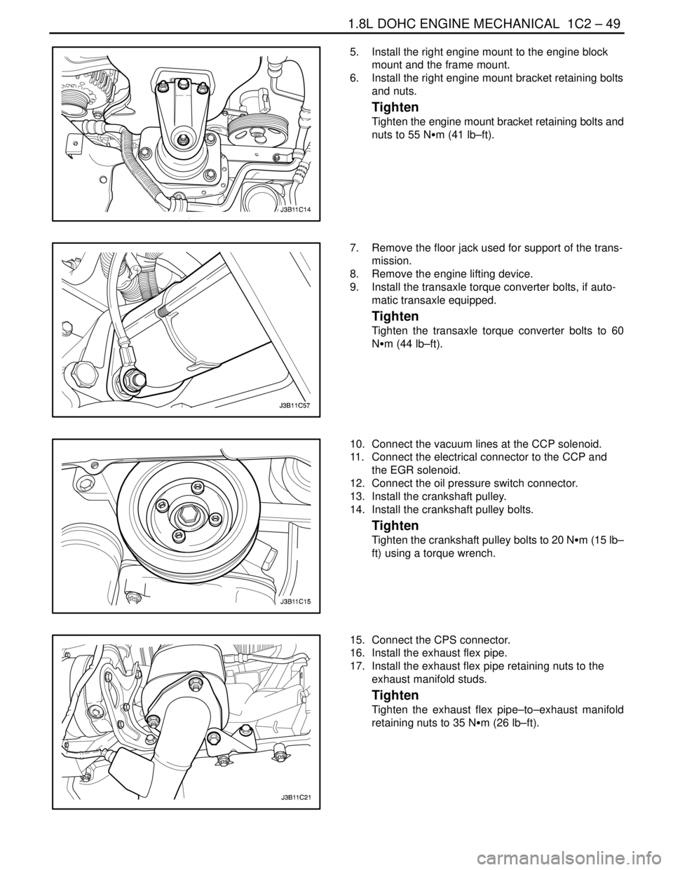
5. Install the right engine mount to the engine block
mount and the frame mount.
6. Install the right engine mount bracket retaining bolts
and nuts.
Tighten
Tighten the engine mount bracket retaining bolts and
nuts to 55 NSm (41 lb–ft).
7. Remove the floor jack used for support of the trans-
mission.
8. Remove the engine lifting device.
9. Install the transaxle torque converter bolts, if auto-
matic transaxle equipped.
Tighten
Tighten the transaxle torque converter bolts to 60
NSm (44 lb–ft).
10. Connect the vacuum lines at the CCP solenoid.
11. Connect the electrical connector to the CCP and
the EGR solenoid.
12. Connect the oil pressure switch connector.
13. Install the crankshaft pulley.
14. Install the crankshaft pulley bolts.
Tighten
Tighten the crankshaft pulley bolts to 20 NSm (15 lb–
ft) using a torque wrench.
15. Connect the CPS connector.
16. Install the exhaust flex pipe.
17. Install the exhaust flex pipe retaining nuts to the
exhaust manifold studs.
Tighten
Tighten the exhaust flex pipe–to–exhaust manifold
retaining nuts to 35 NSm (26 lb–ft).