2004 DAEWOO NUBIRA check oil
[x] Cancel search: check oilPage 112 of 2643
1.4L/1.6L DOHC ENGINE MECHANICAL 1C1 – 69
DAEWOO V–121 BL4
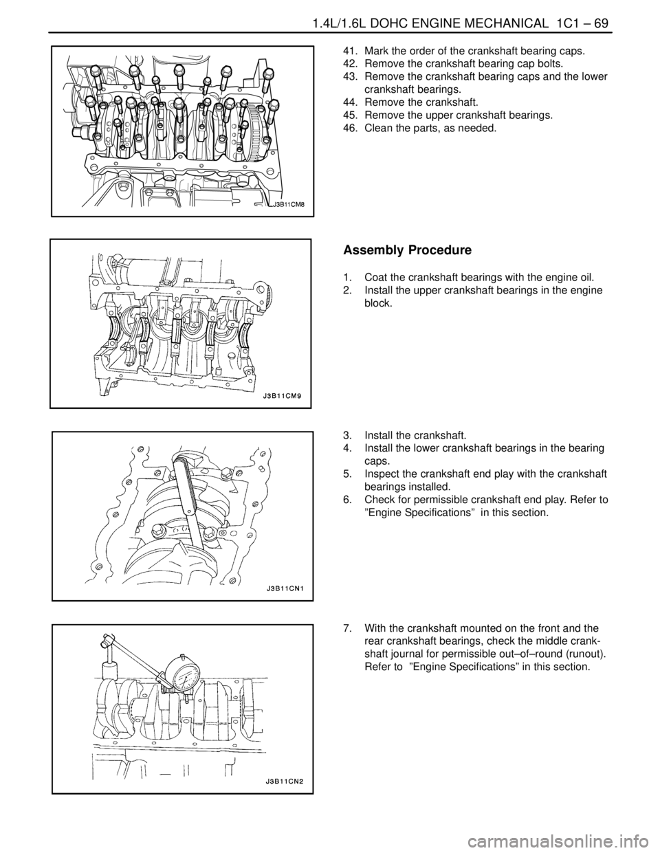
41. Mark the order of the crankshaft bearing caps.
42. Remove the crankshaft bearing cap bolts.
43. Remove the crankshaft bearing caps and the lower
crankshaft bearings.
44. Remove the crankshaft.
45. Remove the upper crankshaft bearings.
46. Clean the parts, as needed.
Assembly Procedure
1. Coat the crankshaft bearings with the engine oil.
2. Install the upper crankshaft bearings in the engine
block.
3. Install the crankshaft.
4. Install the lower crankshaft bearings in the bearing
caps.
5. Inspect the crankshaft end play with the crankshaft
bearings installed.
6. Check for permissible crankshaft end play. Refer to
”Engine Specifications” in this section.
7. With the crankshaft mounted on the front and the
rear crankshaft bearings, check the middle crank-
shaft journal for permissible out–of–round (runout).
Refer to ”Engine Specifications” in this section.
Page 116 of 2643
1.4L/1.6L DOHC ENGINE MECHANICAL 1C1 – 73
DAEWOO V–121 BL4
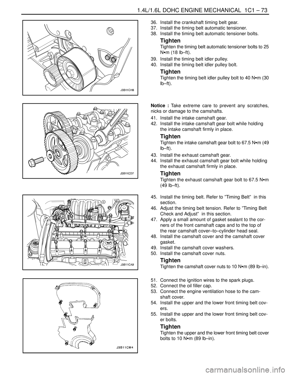
36. Install the crankshaft timing belt gear.
37. Install the timing belt automatic tensioner.
38. Install the timing belt automatic tensioner bolts.
Tighten
Tighten the timing belt automatic tensioner bolts to 25
NSm (18 lb–ft).
39. Install the timing belt idler pulley.
40. Install the timing belt idler pulley bolt.
Tighten
Tighten the timing belt idler pulley bolt to 40 NSm (30
lb–ft).
Notice : Take extreme care to prevent any scratches,
nicks or damage to the camshafts.
41. Install the intake camshaft gear.
42. Install the intake camshaft gear bolt while holding
the intake camshaft firmly in place.
Tighten
Tighten the intake camshaft gear bolt to 67.5 NSm (49
lb–ft).
43. Install the exhaust camshaft gear.
44. Install the exhaust camshaft gear bolt while holding
the exhaust camshaft firmly in place.
Tighten
Tighten the exhaust camshaft gear bolt to 67.5 NSm
(49 lb–ft).
45. Install the timing belt. Refer to ”Timing Belt” in this
section.
46. Adjust the timing belt tension. Refer to ”Timing Belt
Check and Adjust” in this section.
47. Apply a small amount of gasket sealant to the cor-
ners of the front camshaft caps and to the top of
the rear camshaft cover–to–cylinder head seal.
48. Install the camshaft cover and the camshaft cover
gasket.
49. Install the camshaft cover washers.
50. Install the camshaft cover nuts.
Tighten
Tighten the camshaft cover nuts to 10 NSm (89 lb–in).
51. Connect the ignition wires to the spark plugs.
52. Connect the oil filler cap.
53. Connect the engine ventilation hose to the cam-
shaft cover.
54. Install the upper and the lower front timing belt cov-
ers.
55. Install the upper and the lower front timing belt cov-
er bolts.
Tighten
Tighten the upper and the lower front timing belt cover
bolts to 10 NSm (89 lb–in).
Page 121 of 2643
SECTION : 1C2
1.8L DOHC ENGINE MECHANICAL
CAUTION : Disconnect the negative battery cable before removing or installing any electrical unit or when a tool
or equipment could easily come in contact with exposed electrical terminals. Disconnecting this cable will help
prevent personal injury and damage to the vehicle. The ignition must also be in LOCK unless otherwise noted.
TABLE OF CONTENTS
SPECIFICATIONS1C2–2 . . . . . . . . . . . . . . . . . . . . . . . . .
Engine Specifications 1C2–2. . . . . . . . . . . . . . . . . . . . .
Fastener Tightening Specifcations 1C2–4. . . . . . . . . .
SPECIAL TOOLS1C2–6 . . . . . . . . . . . . . . . . . . . . . . . . . .
Special Tools Table 1C2–6. . . . . . . . . . . . . . . . . . . . . . .
COMPONENT LOCATOR1C2–8 . . . . . . . . . . . . . . . . . . .
Upper End 1C2–8. . . . . . . . . . . . . . . . . . . . . . . . . . . . . . .
Lower End 1C2–10. . . . . . . . . . . . . . . . . . . . . . . . . . . . . .
MAINTENANCE AND REPAIR1C2–12 . . . . . . . . . . . . .
ON–VEHICLE SERVICE 1C2–12. . . . . . . . . . . . . . . . . . .
Camshaft Cover 1C2–12. . . . . . . . . . . . . . . . . . . . . . . . .
Cylinder Head and Gasket 1C2–13. . . . . . . . . . . . . . . .
Camshafts 1C2–22. . . . . . . . . . . . . . . . . . . . . . . . . . . . . .
Timing Belt Check and Adjust 1C2–24. . . . . . . . . . . . .
Timing Belt 1C2–28. . . . . . . . . . . . . . . . . . . . . . . . . . . . .
Oil Pan 1C2–32. . . . . . . . . . . . . . . . . . . . . . . . . . . . . . . . .
Oil Pump 1C2–33. . . . . . . . . . . . . . . . . . . . . . . . . . . . . . .
Engine Mount 1C2–37. . . . . . . . . . . . . . . . . . . . . . . . . . .
Intake Manifold 1C2–38. . . . . . . . . . . . . . . . . . . . . . . . . . Exhaust Manifold 1C2–41. . . . . . . . . . . . . . . . . . . . . . . .
Camshaft Gears 1C2–43. . . . . . . . . . . . . . . . . . . . . . . . .
Rear Timing Belt Cover 1C2–44. . . . . . . . . . . . . . . . . . .
Engine 1C2–46. . . . . . . . . . . . . . . . . . . . . . . . . . . . . . . . .
Pistions and Rods 1C2–51. . . . . . . . . . . . . . . . . . . . . . .
UNIT REPAIR 1C2–56. . . . . . . . . . . . . . . . . . . . . . . . . . . .
Cylinder Head and Valve Train Components 1C2–56.
Crankshaft 1C2–63. . . . . . . . . . . . . . . . . . . . . . . . . . . . . .
Crankshaft Bearing and Connecting Rod
Beadings – Gauging Plastics 1C2–72. . . . . . . . . . . .
GENERAL DESCRIPTION AND SYSTEM
OPERATION1C2–75 . . . . . . . . . . . . . . . . . . . . . . . . . . . .
Cylinder Head and Gasket 1C2–75. . . . . . . . . . . . . . . .
Crankshaft 1C2–75. . . . . . . . . . . . . . . . . . . . . . . . . . . . . .
Timing Belt 1C2–75. . . . . . . . . . . . . . . . . . . . . . . . . . . . .
Oil Pump 1C2–75. . . . . . . . . . . . . . . . . . . . . . . . . . . . . . .
Oil Pan 1C2–75. . . . . . . . . . . . . . . . . . . . . . . . . . . . . . . . .
Exhaust Manifold 1C2–75. . . . . . . . . . . . . . . . . . . . . . . .
Intake Manifold 1C2–75. . . . . . . . . . . . . . . . . . . . . . . . . .
Camshaft 1C2–75. . . . . . . . . . . . . . . . . . . . . . . . . . . . . . .
Page 127 of 2643
1.8L DOHC ENGINE MECHANICAL 1C2 – 7
DAEWOO V–121 BL4
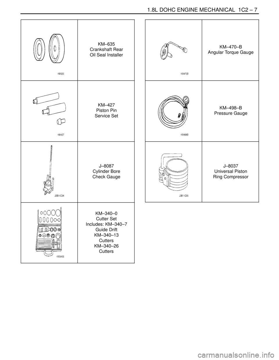
KM–635
Crankshaft Rear
Oil Seal Installer
KM–427
Piston Pin
Service Set
J–8087
Cylinder Bore
Check Gauge
KM–340–0
Cutter Set
Includes: KM–340–7
Guide Drift
KM–340–13
Cutters
KM–340–26
Cutters
KM–470–B
Angular Torque Gauge
KM–498–B
Pressure Gauge
J–8037
Universal Piston
Ring Compressor
Page 143 of 2643
1.8L DOHC ENGINE MECHANICAL 1C2 – 23
DAEWOO V–121 BL4
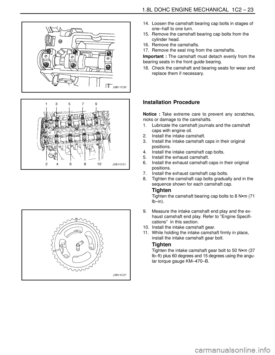
14. Loosen the camshaft bearing cap bolts in stages of
one–half to one turn.
15. Remove the camshaft bearing cap bolts from the
cylinder head.
16. Remove the camshafts.
17. Remove the seal ring from the camshafts.
Important : The camshaft must detach evenly from the
bearing seats in the front guide bearing.
18. Check the camshaft and bearing seats for wear and
replace them if necessary.
Installation Procedure
Notice : Take extreme care to prevent any scratches,
nicks or damage to the camshafts.
1. Lubricate the camshaft journals and the camshaft
caps with engine oil.
2. Install the intake camshaft.
3. Install the intake camshaft caps in their original
positions.
4. Install the intake camshaft cap bolts.
5. Install the exhaust camshaft.
6. Install the exhaust camshaft caps in their original
positions.
7. Install the exhaust camshaft cap bolts.
8. Tighten the camshaft cap bolts gradually and in the
sequence shown for each camshaft cap.
Tighten
Tighten the camshaft bearing cap bolts to 8 NSm (71
lb–in).
9. Measure the intake camshaft end play and the ex-
haust camshaft end play. Refer to ”Engine Specifi-
cations” in this section.
10. Install the intake camshaft gear.
11. While holding the intake camshaft firmly in place,
install the intake camshaft gear bolt.
Tighten
Tighten the intake camshaft gear bolt to 50 NSm (37
lb–ft) plus 60 degrees and 15 degrees using the angu-
lar torque gauge KM–470–B.
Page 154 of 2643

1C2 – 34I1.8L DOHC ENGINE MECHANICAL
DAEWOO V–121 BL4
3. Install the adapter KM–135 in place of the oil pres-
sure switch.
4. Connect the pressure gauge KM–498–B to the
adapter.
5. Start the engine and check the oil pressure at idle
speed and engine temperature of 80°C (176°F).
The minimum oil pressure should be 30 kPa (4.35
psi).
6. Stop the engine and remove the pressure gauge
KM–498–B and the adapter KM–135.
7. Install the oil pressure switch.
Tighten
Tighten the oil pressure switch to 40 NSm (30 lb–ft).
8. Connect the electrical connector to the oil pressure
switch.
9. Install the right front wheel well oil pan scraper. Re-
fer to Section 9R, Body Front End.
10. Check the oil level. Add oil until it reaches the full
mark.
Removal Procedure
1. Disconnect the negative battery cable.
2. Remove the timing belt. Refer to ”Timing Belt” in
this section.
3. Remove the rear timing belt cover. Refer to ”Rear
Timing Belt Cover” in this section.
4. Disconnect the oil pressure switch connector.
5. Remove the oil pan. Refer to ”Oil Pan” in this sec-
tion.
6. Remove the oil suction pipe and support bracket
bolts.
7. Remove the oil suction pipe.
Page 171 of 2643
1.8L DOHC ENGINE MECHANICAL 1C2 – 51
DAEWOO V–121 BL4
43. Connect the lower radiator hose to the coolant pipe.
44. Connect the upper radiator hose to the thermostat
housing.
45. Connect the heater inlet hose to the cylinder head.
46. Connect the heater outlet hose to the coolant pipe.
47. Connect the coolant surge tank hose to the coolant
pipe.
48. Connect the coolant hose to the throttle body.
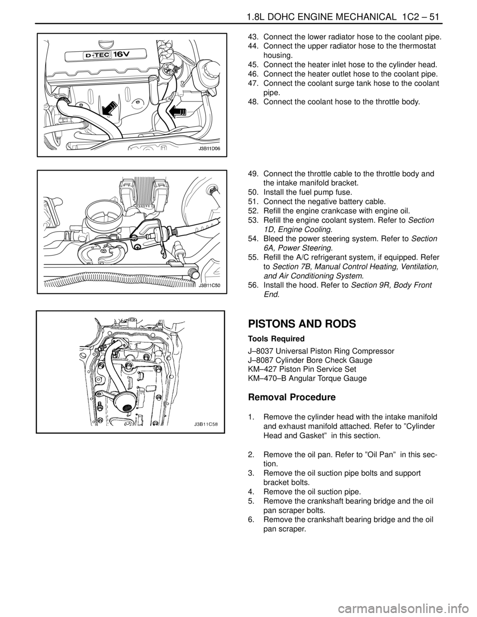
49. Connect the throttle cable to the throttle body and
the intake manifold bracket.
50. Install the fuel pump fuse.
51. Connect the negative battery cable.
52. Refill the engine crankcase with engine oil.
53. Refill the engine coolant system. Refer to Section
1D, Engine Cooling.
54. Bleed the power steering system. Refer to Section
6A, Power Steering.
55. Refill the A/C refrigerant system, if equipped. Refer
to Section 7B, Manual Control Heating, Ventilation,
and Air Conditioning System.
56. Install the hood. Refer to Section 9R, Body Front
End.
PISTONS AND RODS
Tools Required
J–8037 Universal Piston Ring Compressor
J–8087 Cylinder Bore Check Gauge
KM–427 Piston Pin Service Set
KM–470–B Angular Torque Gauge
Removal Procedure
1. Remove the cylinder head with the intake manifold
and exhaust manifold attached. Refer to ”Cylinder
Head and Gasket” in this section.
2. Remove the oil pan. Refer to ”Oil Pan” in this sec-
tion.
3. Remove the oil suction pipe bolts and support
bracket bolts.
4. Remove the oil suction pipe.
5. Remove the crankshaft bearing bridge and the oil
pan scraper bolts.
6. Remove the crankshaft bearing bridge and the oil
pan scraper.
Page 173 of 2643

1.8L DOHC ENGINE MECHANICAL 1C2 – 53
DAEWOO V–121 BL4
8. Inspect the piston for fit to the connecting rod.
9. Inspect the engine block deck surface for flatness
using a straight edge and a feeler gauge. Refer to
”Engine Specifications” in this section.
10. Inspect the bearing bore for concentricity and align-
ment using cylinder bore check gauge J–8087. Re-
fer to ”Engine Specifications” in this section. If the
bearing bore is beyond specifications, replace the
engine block.
11. Inspect the engine block cylinder bore for wear,
runout, ridging and taper using a bore gauge. Refer
to ”Engine Specifications” in this section.
12. Inspect the engine block cylinder bore for glazing.
Lightly hone the cylinder bore as necessary.
Installation Procedure
Important : For ease of installation of the piston pin, the
connecting rod should be heated to 2805C. Heat the upper
connecting rod only. Use commercial thermocolor materi-
al to determine the correct temperature. When the thermo-
color material changes from black to green, the tempera-
ture is correct for installation.
1. Align the notch on the piston and connecting rod so
that the proper sides will be facing the front of the
engine.
2. Install the piston pin guide through the piston and
the connecting rod.
3. Coat the piston pin with clean oil.
4. Install the piston pin into the opposite side of the
piston.
5. Install the piston pin into the piston and connecting
rod assembly using the piston pin service set
KM–427.
6. Select a set of new piston rings.
7. Measure the piston ring gap using a feeler gauge.
Refer to ”Engine Specifications” in this section.
8. Increase the piston ring gap by carefully filing off
excess material if the piston ring gap is below spec-
ifications.