Page 1792 of 2643
5A2 – 202IAISIN AUTOMATIC TRANSAXLE
DAEWOO V–121 BL4
Upper Valve Body Spring
S During reassembly, please refer to the spring specifications below to help you do discriminate between the differ-
ent springs.
MarkName (Color)Free length/Outer diameter mm
(in.)Total number of
coils
A3–4 shift timing valve (Pink)28.41 (1.1185) / 6.4 (0.252)10.49
B2nd brake accumulator piston,(None)
Inner45.90 (1.8071) / 10.5 (0.413)16.9
C2nd brake accumulator piston,(White)
Outer69.00 (2.7165) / 16.0 (0.630)15.1
DReverse clutch accumulator piston
(None)65.40(2.5748) / 17.0 (0.669)13.7
E3–4 shift valve (Red)25.50 (1.0039) / 9.73 (0.3831)7.75
FSecondary regulator valve (White)34.56 (1.3606) / 8.8 (0.346)12.27
GReverse control valve (None)25.58 (1.0071) / 8.64 (0.3402)8.75
HLock up control valve (Yellow)20.87 (0.8217) / 5.55 (0.2185)11.15
Page 1808 of 2643

5A2 – 218IAISIN AUTOMATIC TRANSAXLE
DAEWOO V–121 BL4
GENERAL DESCRIPTION
AND SYSTEM OPERATION
TRANSAXLE DESCRIPTION
The new automatic transmission is an electronically con-
trolled 4–speed automatic transmission with Lock–up
mechanism.
The transmission is mainly composed of the torque con-
verter with lock up clutch, newly developed 4–speed plan-
etary gear unit, the hydraulic control system and the elec-
tric control system.
ELECTRONICAL COMPONENTS
Transmission Control Module (TCM)
The TCM primarily controls shift points and lockup en-
gagement. It is located on the driver side under the instru-
ment panel.
The transmission is controlled by an electronic shift sys-
tem. The Transmission Control Module (TCM) processes
input signals. From the information received, the TCM
controls the transmission hydraulic system.
The electronic shift system consists of the following :
S Transmission control module (TCM)
S Shift solenoids (SS1 and SS2)
S Pressure control solenoid (PCS)
S Lockup solenoid
S Input shaft speed (ISS) sensor
S Output shaft speed (OSS) sensor
S Transmission Fluid Temperature (TFT) sensor
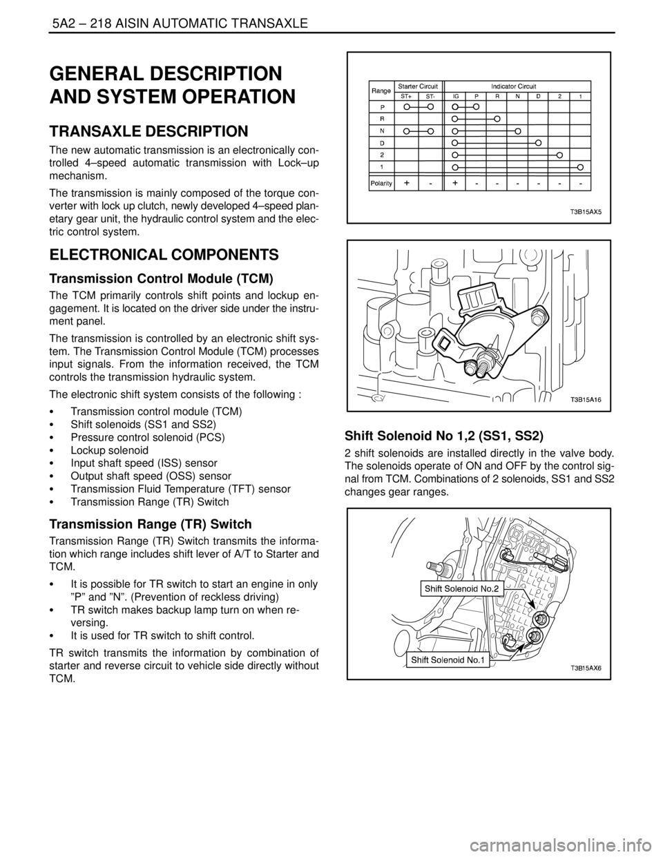
S Transmission Range (TR) Switch
Transmission Range (TR) Switch
Transmission Range (TR) Switch transmits the informa-
tion which range includes shift lever of A/T to Starter and
TCM.
S It is possible for TR switch to start an engine in only
”P” and ”N”. (Prevention of reckless driving)
S TR switch makes backup lamp turn on when re-
versing.
S It is used for TR switch to shift control.
TR switch transmits the information by combination of
starter and reverse circuit to vehicle side directly without
TCM.
Shift Solenoid No 1,2 (SS1, SS2)
2 shift solenoids are installed directly in the valve body.
The solenoids operate of ON and OFF by the control sig-
nal from TCM. Combinations of 2 solenoids, SS1 and SS2
changes gear ranges.
Page 1809 of 2643

AISIN AUTOMATIC TRANSAXLE 5A2 – 219
DAEWOO V–121 BL4
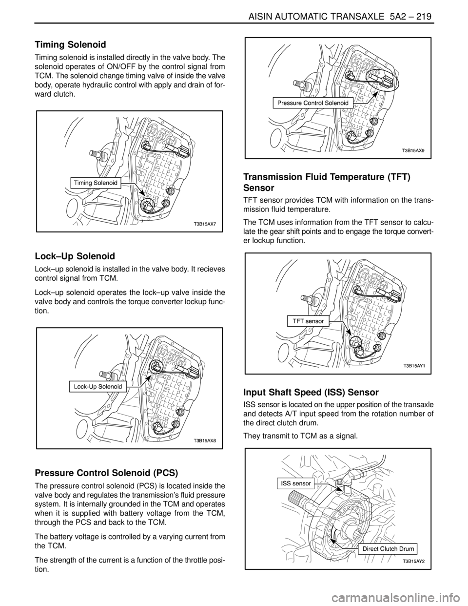
Timing Solenoid
Timing solenoid is installed directly in the valve body. The
solenoid operates of ON/OFF by the control signal from
TCM. The solenoid change timing valve of inside the valve
body, operate hydraulic control with apply and drain of for-
ward clutch.
Lock–Up Solenoid
Lock–up solenoid is installed in the valve body. It recieves
control signal from TCM.
Lock–up solenoid operates the lock–up valve inside the
valve body and controls the torque converter lockup func-
tion.
Pressure Control Solenoid (PCS)
The pressure control solenoid (PCS) is located inside the
valve body and regulates the transmission’s fluid pressure
system. It is internally grounded in the TCM and operates
when it is supplied with battery voltage from the TCM,
through the PCS and back to the TCM.
The battery voltage is controlled by a varying current from
the TCM.
The strength of the current is a function of the throttle posi-
tion.
Transmission Fluid Temperature (TFT)
Sensor
TFT sensor provides TCM with information on the trans-
mission fluid temperature.
The TCM uses information from the TFT sensor to calcu-
late the gear shift points and to engage the torque convert-
er lockup function.
Input Shaft Speed (ISS) Sensor
ISS sensor is located on the upper position of the transaxle
and detects A/T input speed from the rotation number of
the direct clutch drum.
They transmit to TCM as a signal.
Page 1811 of 2643
AISIN AUTOMATIC TRANSAXLE 5A2 – 221
DAEWOO V–121 BL4
HYDRAULIC CONTROL SYSTEM
Based on the hydraulic pressure created by the oil pump, TCM sends signals to solenoid and hydraulic control system
governs the hydraulic pressure acting on the torque converter, planetary gear, clutches and brakes in accordance with
the vehicle driving conditions.
Page 1812 of 2643

5A2 – 222IAISIN AUTOMATIC TRANSAXLE
DAEWOO V–121 BL4
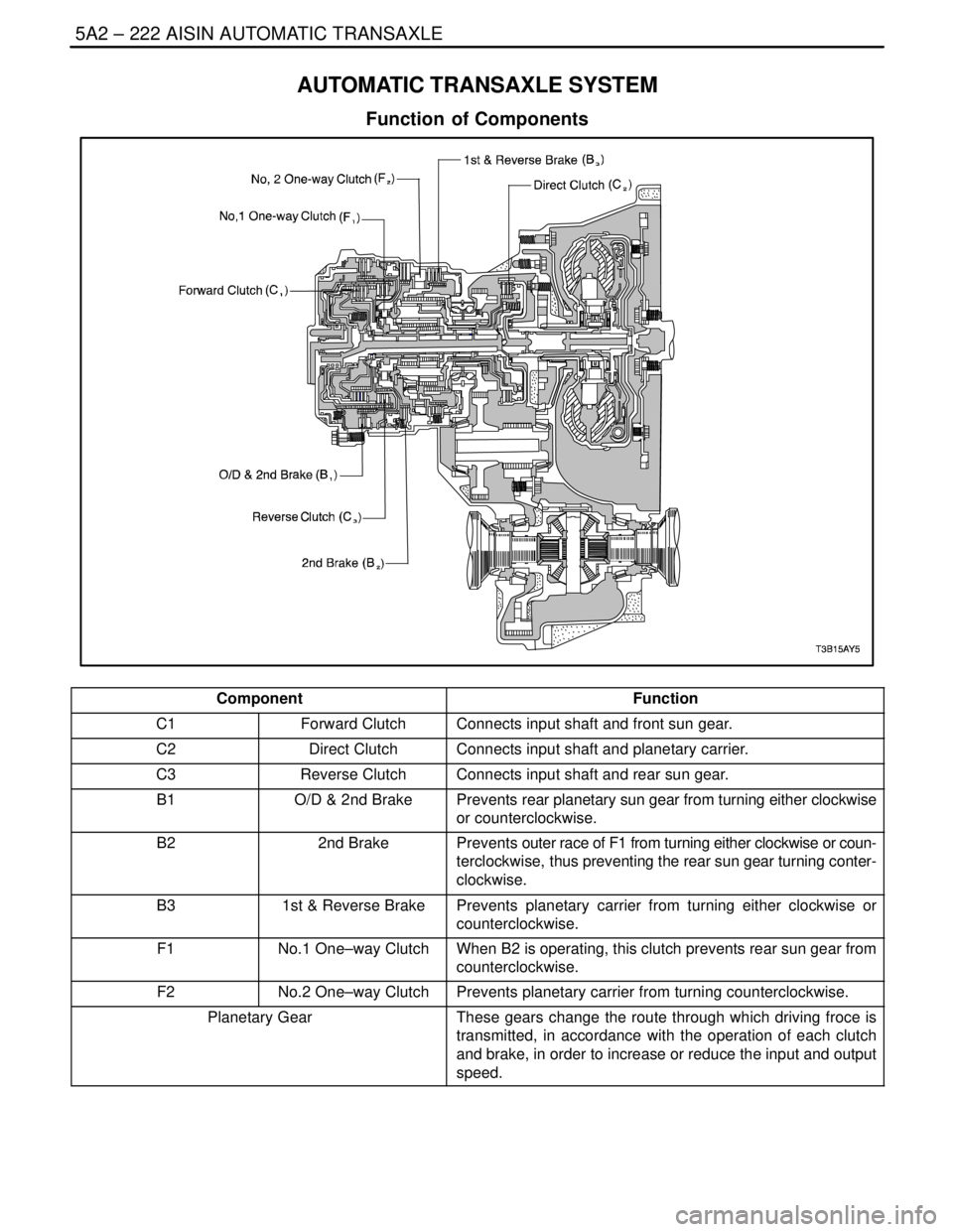
AUTOMATIC TRANSAXLE SYSTEM
Function of Components
ComponentFunction
C1Forward ClutchConnects input shaft and front sun gear.
C2Direct ClutchConnects input shaft and planetary carrier.
C3Reverse ClutchConnects input shaft and rear sun gear.
B1O/D & 2nd BrakePrevents rear planetary sun gear from turning either clockwise
or counterclockwise.
B22nd BrakePrevents outer race of F1 from turning either clockwise or coun-
terclockwise, thus preventing the rear sun gear turning conter-
clockwise.
B31st & Reverse BrakePrevents planetary carrier from turning either clockwise or
counterclockwise.
F1No.1 One–way ClutchWhen B2 is operating, this clutch prevents rear sun gear from
counterclockwise.
F2No.2 One–way ClutchPrevents planetary carrier from turning counterclockwise.
Planetary GearThese gears change the route through which driving froce is
transmitted, in accordance with the operation of each clutch
and brake, in order to increase or reduce the input and output
speed.
Page 1813 of 2643
AISIN AUTOMATIC TRANSAXLE 5A2 – 223
DAEWOO V–121 BL4
Operations of Clutches and Brakes
Clutch & BrakeOperation
C1Forward ClutchConnects intermediate shaft and front sun gear.
C2Direct ClutchConnects input shaft and Planetary carrier.
C3Reverse ClutchConnects intermediate shaft and rear sun gear.
B1O/D & 2nd BrakeLock rear sun gear
B22nd BrakeLock rear sun gear
B31st & Reverse BrakeLock Planetary carrier
F11way Clutch No.1Lock counterclockwise rotation of rear sun gear, when B2 op-
erations
F21way Clutch No.2Lock counterclockwise rotation of planetary carrier
Page 1814 of 2643
5A2 – 224IAISIN AUTOMATIC TRANSAXLE
DAEWOO V–121 BL4
PositionSolenoidClutchBrakeOne–way
Clutch
Shift 1Shift 2TimingC1C2C3B1B2B3F1F2
PONONOFFOFFOFFOFFOFFOFFOFFOF
–FOF
–F
RV<9
Km/
hONONOFFOFFOFFONOFFOFFONOF
–FOF
–F
V�
9K
m/hONONONOFFOFFOFFOFFOFFOFFOF
–FOF
–F
NONONOFFOFFOFFOFFOFFOFFOFFOF
–FOF
–F
D1stONONOFFONOFFOFFOFFOFFOFFOF
–FON
2ndONOFFOFFONOFFOFFOFFONOFFONOF
–F
3rdOFFOFFOFFONONOFFOFFONOFFOF
–FOF
–F
(3�
4)OFFONON�
OFFON�
OFFONOFFOFF�
ONONOFFOF
–FOF
–F
4thOFFONOFFOFFONOFFONONOFFOF
–FOF
–F
21stONONOFFONOFFOFFOFFOFFOFFOF
–FON
2ndONOFFOFFONOFFOFFONONOFFONOF
–F
3rdOFFOFFOFFONONOFFOFFONOFFOF
–FOF
–F
11stONONOFFONOFFOFFOFFOFFONOF
–FON
2ndONOFFOFFONOFFOFFONONOFFONOF
–F
Page 1815 of 2643
AISIN AUTOMATIC TRANSAXLE 5A2 – 225
DAEWOO V–121 BL4
D–1st Gear
PositionSolenoidClutchBrake1 way
Clutch
Shift 1Shift 2TimingC1C2C3B1B2B3F1F2
D1stONONOFFONOFFOFFOFFOFFOFFOF
–FON
11stONONOFFONOFFOFFOFFOFFONOF
–FON
”D” – 1st Gear
1. Input shaft rotates clockwise.
S Forward clutch (C1) operates. (Connect input shaft to front sun gear)
2. Front sun gear rotates clockwise.
3. Planetary short pinion rotates itself counterclockwise.
4. Planetary long Pinion rotates itself clockwise.
5. Planetary carrier is going to rotate counterclockwise.
S One way clutch No.2(F2) operates. (Lock revolves counterclockwise of planetary carrier)