Page 1744 of 2643
5A2 – 154IAISIN AUTOMATIC TRANSAXLE
DAEWOO V–121 BL4
77. Install the forward clutch hub to the transaxle case.
78. Coat the thrust bearing race with petroleum jelly
and install it onto the forward clutch hub.
S Race:
Inner diameter: 19.3 mm (1.760 in.)
Outer diameter: 30.6 mm (1.205 in.)
79. Install the thrust bearing race and thrust needle roll-
er bearing to the forward & reverse clutch assem-
bly.
S Race and bearing diameter: mm(in.)
Inner diameterOuter diameter
Race18.1 (0.713)28.2 (1.110)
Bearing18.1 (0.713)29.6 (1.165)
80. Install the forward & reverse clutch assembly to the
transaxle case.
Page 1746 of 2643

5A2 – 156IAISIN AUTOMATIC TRANSAXLE
DAEWOO V–121 BL4
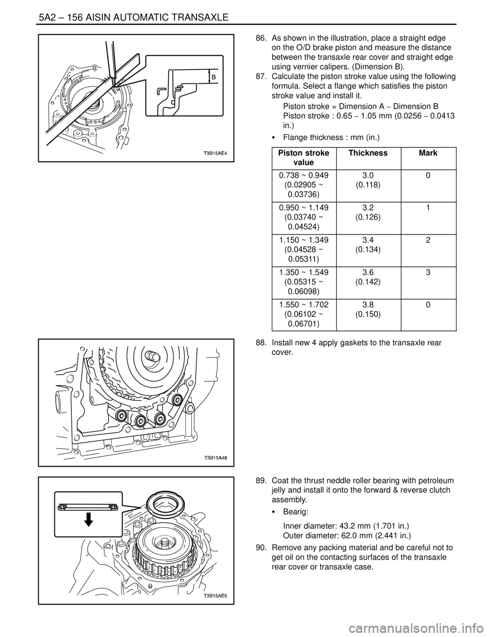
86. As shown in the illustration, place a straight edge
on the O/D brake piston and measure the distance
between the transaxle rear cover and straight edge
using vernier calipers. (Dimension B).
87. Calculate the piston stroke value using the following
formula. Select a flange which satisfies the piston
stroke value and install it.
Piston stroke = Dimension A � Dimension B
Piston stroke : 0.65 � 1.05 mm (0.0256 � 0.0413
in.)
S Flange thickness : mm (in.)
Piston stroke
value
ThicknessMark
0.738 ~ 0.949
(0.02905 ~
0.03736)3.0
(0.118)0
0.950 ~ 1.149
(0.03740 ~
0.04524)3.2
(0.126)1
1.150 ~ 1.349
(0.04528 ~
0.05311)3.4
(0.134)2
1.350 ~ 1.549
(0.05315 ~
0.06098)3.6
(0.142)3
1.550 ~ 1.702
(0.06102 ~
0.06701)3.8
(0.150)0
88. Install new 4 apply gaskets to the transaxle rear
cover.
89. Coat the thrust neddle roller bearing with petroleum
jelly and install it onto the forward & reverse clutch
assembly.
S Bearig:
Inner diameter: 43.2 mm (1.701 in.)
Outer diameter: 62.0 mm (2.441 in.)
90. Remove any packing material and be careful not to
get oil on the contacting surfaces of the transaxle
rear cover or transaxle case.
Page 1748 of 2643
5A2 – 158IAISIN AUTOMATIC TRANSAXLE
DAEWOO V–121 BL4
95. Install the direct clutch hub to the transaxle case.
96. Install the thrust bearing race and thrust needle roll-
er bearing to the transaxle case.
S Race and bearing: mm (in.)
Inner diameterOuter diameter
Race20.5 (0.807)32.6 (1.283)
Bearing17.8 (0.701)30.2 (1.189)
97. Install the direct clutch assembly to the transaxle
case.
98. Install new apply gasket.
Page 1751 of 2643
AISIN AUTOMATIC TRANSAXLE 5A2 – 161
DAEWOO V–121 BL4
109. Coat new 6 O–rings with ATF and install them
to the pistons.
110. Coat the 3 springs and 3 accumulator pistons
with ATF, install them to the holes.
S Accumulator spring:
Spring
Free length
Outer
diameter
mm(in.)Color
B1(O/D & 2nd
brake)47.13(1.8555)/
16.0(0.630)Pink
C1(Forward
clutch)57.90(2.2795)/
17.2(0.677)–
C2(Direct
clutch)57.20(2.2520)/
17.5(0.689)Green
111. Coat a new apply gasket with ATF, install it to
the transaxle case.
112. Coat a new brake drum gasket with ATF, install
it to the transaxle case.
113. Install the spring and check valve.
Page 1761 of 2643
AISIN AUTOMATIC TRANSAXLE 5A2 – 171
DAEWOO V–121 BL4
DIRECT CLUTCH
1. Seal Ring
2. Input Shaft Sub–assembly
3. O–Ring
4. Piston
5. O–Ring
6. Return Spring7. Snap Ring
8. Plate
9. Disc
10. Flange
11. Snap Ring
Page 1762 of 2643

5A2 – 172IAISIN AUTOMATIC TRANSAXLE
DAEWOO V–121 BL4
Tools Required
DW240–020 Brake/Clutch Spring Compressor
DW240–040 Direct Clutch Adapter
Disassembly Procedure
WARNING : USE CAUTION WHEN CHECKING COM-
PONENTS WITH COMPRESSED AIR OR PERSONAL
INJURY MAY RESULT.
1. Install the direct clutch and thrust needle roller
bearing on the oil pump.
2. Using a dial indicator, measure the direct clutch
piston stroke while applying and releasing 392 kPa
(57 psi).of compressed air.
Piston stroke: 0.4 � 0.8 mm (0.016 � 0.031 in.)
If the stroke is non–standard, inspect the discs,
plates and flange.
3. Using a screwdriver, remove the snap ring.
4. Remove the flange, 2discs and 2 plates.
5. Place the brake/clutch spring compressor
DW240–020 and direct clutch adapter DW240–040
on the direct clutch return spring and compress.
6. Using a snap ring expander, remove the snap ring.
Notice : Stop the press when the piston return spring is
lowered to the place 1–2 mm (0.039–0.078 in.) from the
snap ring groove, preventing the piston return spring from
being deformed.
Notice : Do not expand the snap ring excessively.
Page 1763 of 2643
AISIN AUTOMATIC TRANSAXLE 5A2 – 173
DAEWOO V–121 BL4
7. Remove the direct clutch return spring.
8. Install the direct clutch on the oil pump.
WARNING : USE CAUTION WHEN REMOVING COM-
PONENTS WITH COMPRESSED AIR OR PERSONAL
INJURY MAY RESULT.
Notice : Blowing off the air may cause the piston’jump–
out.When removing the piston, hold it with your hand using
a waste cloth.
Notice : Take care not to splash ATF when air–blowing.
9. Apply 392 kPa (57 psi) of compressed air to the oil
pump to remove the direct clutch piston.
S When the piston can not be removed as it is
slanted, either blow the air again with the pro-
truding side pushed or remove the piston using
needle nose pliers with vinyl tape on the tip.
10. Using a small screwdriver, remove the O–ring from
the direct clutch piston.
11. Remove the O–ring from the input shaft.
Page 1764 of 2643
5A2 – 174IAISIN AUTOMATIC TRANSAXLE
DAEWOO V–121 BL4
12. Remove the 2 seal rings from the input shaft.
Notice : Do not expand the ring ends excessively.
Inspection Procedure
1. Check to see if the sliding surface of the disc, plate
and flange are worm or burnt. If necessary, replace
them.
S If the lining of the disc is peeling off or discol-
ored, or even if a part of the printed number is
defaced, replace all discs.
S Before assembling new discs, soak them in ATF
for at least 15 minutes.
2. Using vernier calipers, measure the free length of
the direct clutch return spring together with the
spring sheet.
S Standard free length: 36.04 mm (1.4189 in.)
3. Check that the check ball is free by shaking the di-
rect clutch piston.
4. Check that the valve does not leak by applying low–
pressure compressed air.