Page 1775 of 2643
AISIN AUTOMATIC TRANSAXLE 5A2 – 185
DAEWOO V–121 BL4
6. Remove the 2 flanges, 2 discs and plate from the
reverse clutch drum.
7. Using a screwdriver, remove the snap ring.
8. Remove the flange, 3 discs and 3 plates from the
forward clutch drum.
9. Using brake/clutch spring compressor DW240–020
and forward clutch adapter DW240–030, compress
the spring.
10. Using a snap ring expander, remove the snap ring.
Notice : Stop the press when the clutch balancer is low-
ered to the place 1–2 mm (0.039–0.078 in.) from the snap
ring groove, preventing the clutch balancer from being de-
formed.
Notice : Do not expand the snap ring excessively.
Page 1776 of 2643

5A2 – 186IAISIN AUTOMATIC TRANSAXLE
DAEWOO V–121 BL4
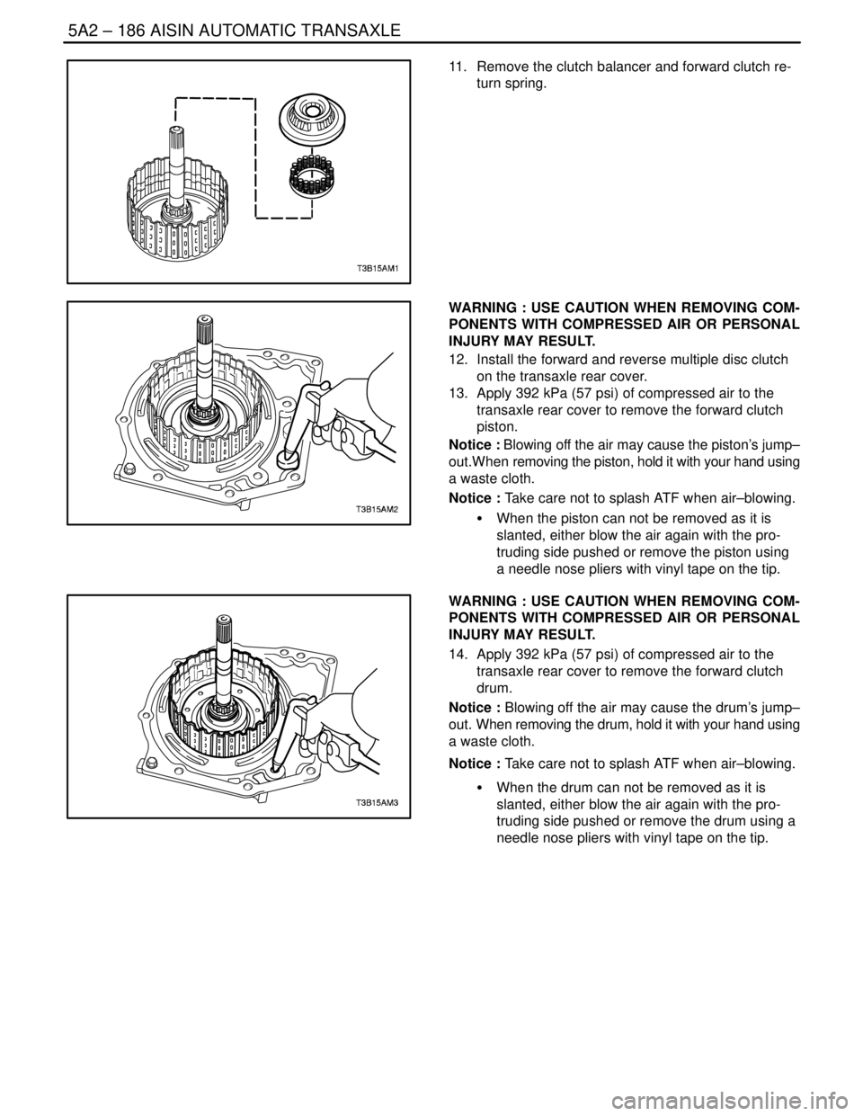
11. Remove the clutch balancer and forward clutch re-
turn spring.
WARNING : USE CAUTION WHEN REMOVING COM-
PONENTS WITH COMPRESSED AIR OR PERSONAL
INJURY MAY RESULT.
12. Install the forward and reverse multiple disc clutch
on the transaxle rear cover.
13. Apply 392 kPa (57 psi) of compressed air to the
transaxle rear cover to remove the forward clutch
piston.
Notice : Blowing off the air may cause the piston’s jump–
out.When removing the piston, hold it with your hand using
a waste cloth.
Notice : Take care not to splash ATF when air–blowing.
S When the piston can not be removed as it is
slanted, either blow the air again with the pro-
truding side pushed or remove the piston using
a needle nose pliers with vinyl tape on the tip.
WARNING : USE CAUTION WHEN REMOVING COM-
PONENTS WITH COMPRESSED AIR OR PERSONAL
INJURY MAY RESULT.
14. Apply 392 kPa (57 psi) of compressed air to the
transaxle rear cover to remove the forward clutch
drum.
Notice : Blowing off the air may cause the drum’s jump–
out. When removing the drum, hold it with your hand using
a waste cloth.
Notice : Take care not to splash ATF when air–blowing.
S When the drum can not be removed as it is
slanted, either blow the air again with the pro-
truding side pushed or remove the drum using a
needle nose pliers with vinyl tape on the tip.
Page 1777 of 2643
AISIN AUTOMATIC TRANSAXLE 5A2 – 187
DAEWOO V–121 BL4
15. Using a small screwdriver, remove the O–ring from
the forward clutch drum.
16. Using a small screwdriver, remove the O–ring from
the intermediate shaft sub–assembly.
Inspection Procedure
1. Check to see if the sliding surface of the disc, plate
flange are worn or burnt. If necessary, replace
them.
S If the lining of the disc is peeling off or discol-
ored, or even if a part of the printed number is
defaced, replace all discs.
S Before assembling new discs, soak them in ATF
for at least 15 minutes.
2. Using vernier calipers, measure the free length of
the spring together with the spring seat.
S Standard free length: 24.04 mm (0.9465 in.)
Page 1778 of 2643
5A2 – 188IAISIN AUTOMATIC TRANSAXLE
DAEWOO V–121 BL4
Assembly Procedure
1. Coat a new O–ring with ATF, and install it to the
intermediate shaft sub–assembly.
2. Coat a new O–ring with ATF, and install it to the
forward clutch drum.
3. Coat the forward clutch drum with ATF, install the
forward clutch drum.
Notice : Be careful not to damage the O–ring and lip seal
of forward clutch drum.
4. Coat the forward clutch piston with ATF, install the
forward clutch piston.
Notice : Be careful not to damage the lip seal of forward
clutch piston.
Page 1779 of 2643
AISIN AUTOMATIC TRANSAXLE 5A2 – 189
DAEWOO V–121 BL4
5. Install the forward clutch return spring and clutch
balancer.
Notice : Be careful not to damage the lip seal of forward
clutch return spring.
6. Place brake/clutch spring compressor DW240–020
and forward clutch adapter DW240–030 on the
clutch balancer and compress the piston return
spring.
7. Using a snap ring expander, install the snap ring.
Notice : Stop the press when the clutch balancer is low-
ered to the place 1–2 mm (0.039–0.078 in.) from the snap
ring groove, preventing the clutch balancer from being de-
formed.
Notice : Do not expand the snap ring excessively.
8. Install the 3 plates, 3 discs and flange.
S Install in order: P � D � P � D � P � D – F
(P = Plate, D = Disc, F = Flange)
9. Using a screwdriver, install the snap ring.
10. Check that the end gap of the snap ring is not
aligned with one of the cutouts.
Page 1780 of 2643

5A2 – 190IAISIN AUTOMATIC TRANSAXLE
DAEWOO V–121 BL4
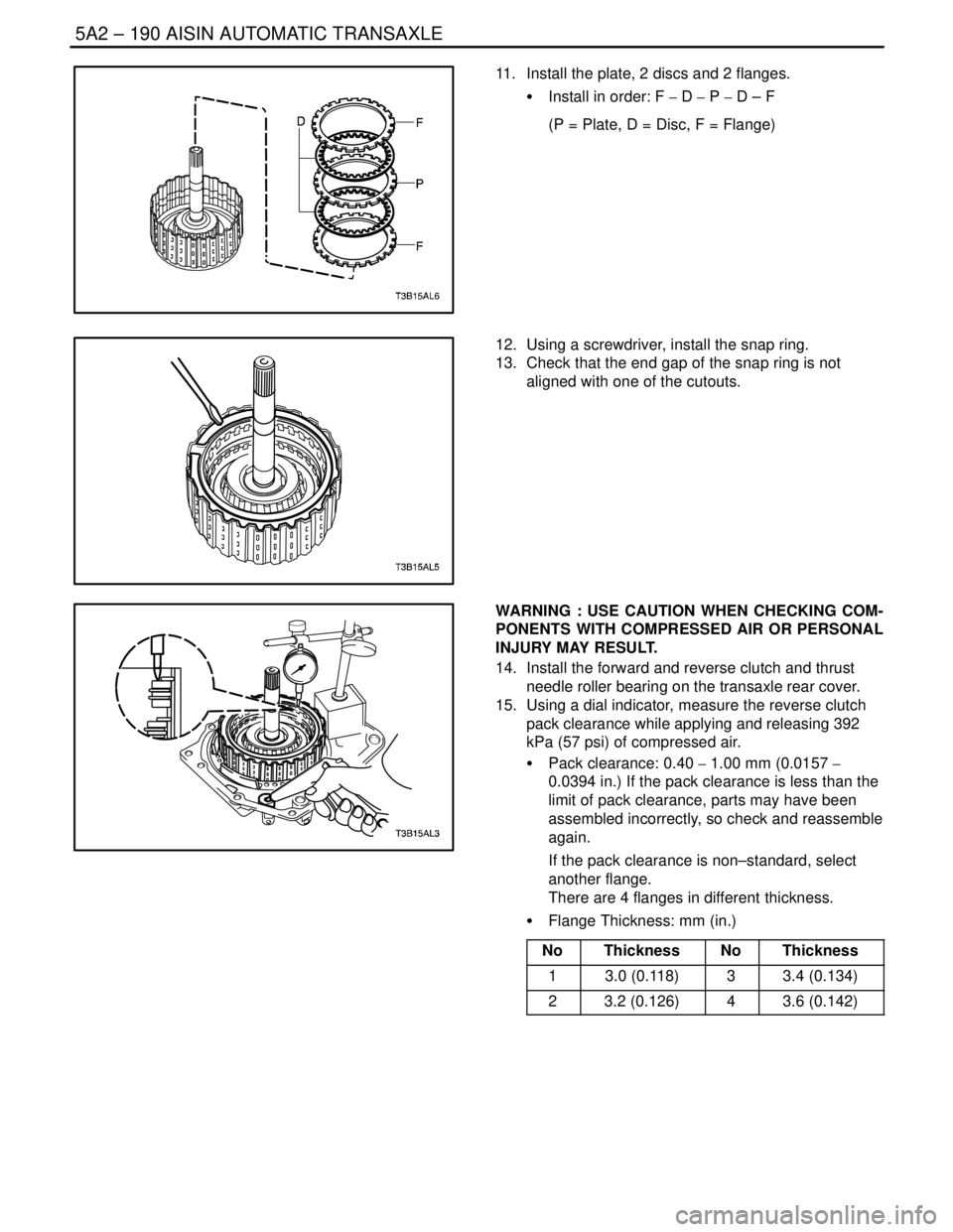
11. Install the plate, 2 discs and 2 flanges.
S Install in order: F � D � P � D – F
(P = Plate, D = Disc, F = Flange)
12. Using a screwdriver, install the snap ring.
13. Check that the end gap of the snap ring is not
aligned with one of the cutouts.
WARNING : USE CAUTION WHEN CHECKING COM-
PONENTS WITH COMPRESSED AIR OR PERSONAL
INJURY MAY RESULT.
14. Install the forward and reverse clutch and thrust
needle roller bearing on the transaxle rear cover.
15. Using a dial indicator, measure the reverse clutch
pack clearance while applying and releasing 392
kPa (57 psi) of compressed air.
S Pack clearance: 0.40 � 1.00 mm (0.0157 �
0.0394 in.) If the pack clearance is less than the
limit of pack clearance, parts may have been
assembled incorrectly, so check and reassemble
again.
If the pack clearance is non–standard, select
another flange.
There are 4 flanges in different thickness.
S Flange Thickness: mm (in.)
No
ThicknessNoThickness
13.0 (0.118)33.4 (0.134)
23.2 (0.126)43.6 (0.142)
Page 1781 of 2643

AISIN AUTOMATIC TRANSAXLE 5A2 – 191
DAEWOO V–121 BL4
16. Install the forward and reverse clutch and thrust
needle roller bearing on the transaxle rear cover.
17. Using a dial indicator and measuring terminal
DW240–120, measure the forward clutch pack
clearance while applying and releasing 392 kpa (57
psi) of compressed air.
S The forward and reverse clutch will come out as
you apply the compressed air. Therefore, while
the checking is being done, press on the input
shaft of the forward and reverse clutch using
stamping machine or alike so that the pressure
is not applied on the forward and reverse clutch.
S Pack clearance: 1.1–1.5 mm (0.043 � 0.059 in.)
If the pack clearance is less than the limit of
pack clearance, parts may have been as-
sembled incorrectly, so check and reassemble
again.
If the pack clearance is non–standard, select
another flange.
There are 4 flanges in different thickness.
S Flange Thickness: mm (in.)
No
ThicknessNoThickness
13.0 (0.118)33.4 (0.134)
23.2 (0.126)43.6 (0.142)
Page 1791 of 2643
AISIN AUTOMATIC TRANSAXLE 5A2 – 201
DAEWOO V–121 BL4
Upper Valve Body
1. Sleeve
2. Key
3. Spring
4. Plunger
5. Lock–up Control Valve
6. Plug
7. Key
8. Secondary Regulator Valve
9. Spring
10. No.2 Check Valve
11. Key
12. Ball
13. No.1 Check Valve
14. Reverse Control Valve
15. Spring
16. Key17. Plug
18. Spring
19. 3–4 Shift Valve
20. Spring
21. O–ring
22. Reverse Clutch Accumulator Piston
23. O–ring
24. Plunger
25. 3–4 Shift Timing Valve
26. Spring
27. O–ring
28. 2nd Brake Accumulator Piston
29. O–ring
30. Spring
31. Upper Valve Body Cover