2004 DAEWOO NUBIRA gear lever
[x] Cancel search: gear leverPage 246 of 2643

1E – 32IENGINE ELECTRICAL
DAEWOO V–121 BL4
the same cable to the positive terminal on the other
battery. Never connect the other end to the nega-
tive terminal of the discharged battery.
CAUTION : To avoid injury do not attach the cable di-
rectly to the negative terminal of the discharged bat-
tery. Doing so could cause sparks and a possible bat-
tery explosion.
6. Clamp one end of the second cable to the negative
terminal of the booster battery. Make the final con-
nection to a solid engine ground (such as the en-
gine lift bracket) at least 450 millimeters (18 inches)
from the discharged battery.
7. Start the engine of the vehicle with the good bat-
tery. Run the engine at a moderate speed for sever-
al minutes. Then start the engine of the vehicle
which has the discharged battery.
8. Remove the jumper cables by reversing the above
sequence exactly. Remove the negative cable from
the vehicle with the discharged battery first. While
removing each clamp, take care that it does not
touch any other metal while the other end remains
attached.
GENERATOR
The Delco–Remy CS charging system has several mod-
els available, including the CS. The number denotes the
outer diameter in millimeters of the stator lamination.
CS generators are equipped with internal regulators. A
Delta stator, a rectifier bridge, and a rotor with slip rings
and brushes are electrically similar to earlier generators.
A conventional pulley and fan are used. There is no test
hole.
Unlike three–wire generators, the CS may be used with
only two connections: battery positive and an ”L’’ terminal
to the charge indicator lamp.
As with other charging systems, the charge indicator lamp
lights when the ignition switch is turned to RUN, and goes
out when the engine is running. If the charge indicator is
on with the engine running, a charging system defect is in-
dicated. This indicator light will glow at full brilliance for
several kinds of defects as well as when the system volt-
age is too high or too low.The regulator voltage setting varies with temperature and
limits the system voltage by controlling rotor field current.
At high speeds, the on–time may be 10 percent and the
off–time 90 percent. At low speeds, with high electrical
loads, on–time may be 90 percent and the off–time 10 per-
cent.
CHARGING SYSTEM
CS generators use a new type of regulator that incorpo-
rates a diode trio. A Delta stator, a rectifier bridge, and a
rotor with slip rings and brushes are electrically similar to
earlier generators. A conventional pulley and fan are used.
There is no test hole.
STARTER
Wound field starter motors have pole pieces, arranged
around the armature, which are energized by wound field
coils.
Enclosed shift lever cranking motors have the shift lever
mechanism and the solenoid plunger enclosed in the drive
housing, protecting them from exposure to dirt, icy condi-
tions, and splashes.
In the basic circuit, solenoid windings are energized when
the switch is closed. The resulting plunger and shift lever
movement causes the pinion to engage the engine fly-
wheel ring gear. The solenoid main contacts close. Crank-
ing then takes place.
When the engine starts, pinion overrun protects the arma-
ture from excessive speed until the switch is opened, at
which time the return spring causes the pinion to disen-
gage. To prevent excessive overrun, the switch should be
released immediately after the engine starts.
STARTING SYSTEM
The engine electrical system includes the battery, the igni-
tion, the starter, the generator, and all the related wiring.
Diagnostic tables will aid in troubleshooting system faults.
When a fault is traced to a particular component, refer to
that component section of the service manual.
The starting system circuit consists of the battery, the
starter motor, the ignition switch, and all the related electri-
cal wiring. All of these components are connected electri-
cally.
Page 1154 of 2643
4G – 2IPARKING BRAKE
DAEWOO V–121 BL4
MAINTENANCE AND REPAIR
ON–VEHICLE SERVICE
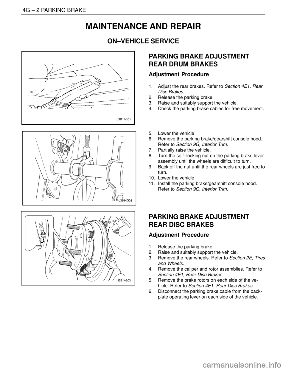
PARKING BRAKE ADJUSTMENT
REAR DRUM BRAKES
Adjustment Procedure
1. Adjust the rear brakes. Refer to Section 4E1, Rear
Disc Brakes.
2. Release the parking brake.
3. Raise and suitably support the vehicle.
4. Check the parking brake cables for free movement.
5. Lower the vehicle
6. Remove the parking brake/gearshift console hood.
Refer to Section 9G, Interior Trim.
7. Partially raise the vehicle.
8. Turn the self–locking nut on the parking brake lever
assembly until the wheels are difficult to turn.
9. Back off the nut until the rear wheels are just free to
turn.
10. Lower the vehicle
11. Install the parking brake/gearshift console hood.
Refer to Section 9G, Interior Trim.
PARKING BRAKE ADJUSTMENT
REAR DISC BRAKES
Adjustment Procedure
1. Release the parking brake.
2. Raise and suitably support the vehicle.
3. Remove the rear wheels. Refer to Section 2E, Tires
and Wheels.
4. Remove the caliper and rotor assemblies. Refer to
Section 4E1, Rear Disc Brakes.
5. Remove the brake rotors on each side of the ve-
hicle. Refer to Section 4E1, Rear Disc Brakes.
6. Disconnect the parking brake cable from the back-
plate operating lever on each side of the vehicle.
Page 1155 of 2643
PARKING BRAKE 4G – 3
DAEWOO V–121 BL4
7. Inspect and replace any parts of doubtful strength
or quality. This can be shown by discoloration from
heat or stress.
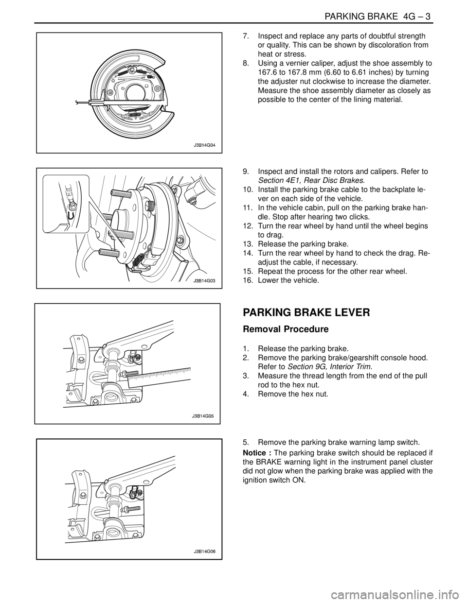
8. Using a vernier caliper, adjust the shoe assembly to
167.6 to 167.8 mm (6.60 to 6.61 inches) by turning
the adjuster nut clockwise to increase the diameter.
Measure the shoe assembly diameter as closely as
possible to the center of the lining material.
9. Inspect and install the rotors and calipers. Refer to
Section 4E1, Rear Disc Brakes.
10. Install the parking brake cable to the backplate le-
ver on each side of the vehicle.
11. In the vehicle cabin, pull on the parking brake han-
dle. Stop after hearing two clicks.
12. Turn the rear wheel by hand until the wheel begins
to drag.
13. Release the parking brake.
14. Turn the rear wheel by hand to check the drag. Re-
adjust the cable, if necessary.
15. Repeat the process for the other rear wheel.
16. Lower the vehicle.
PARKING BRAKE LEVER
Removal Procedure
1. Release the parking brake.
2. Remove the parking brake/gearshift console hood.
Refer to Section 9G, Interior Trim.
3. Measure the thread length from the end of the pull
rod to the hex nut.
4. Remove the hex nut.
5. Remove the parking brake warning lamp switch.
Notice : The parking brake switch should be replaced if
the BRAKE warning light in the instrument panel cluster
did not glow when the parking brake was applied with the
ignition switch ON.
Page 1156 of 2643
4G – 4IPARKING BRAKE
DAEWOO V–121 BL4
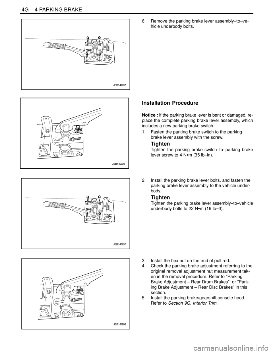
6. Remove the parking brake lever assembly–to–ve-
hicle underbody bolts.
Installation Procedure
Notice : If the parking brake lever is bent or damaged, re-
place the complete parking brake lever assembly, which
includes a new parking brake switch.
1. Fasten the parking brake switch to the parking
brake lever assembly with the screw.
Tighten
Tighten the parking brake switch–to–parking brake
lever screw to 4 NSm (35 lb–in).
2. Install the parking brake lever bolts, and fasten the
parking brake lever assembly to the vehicle under-
body.
Tighten
Tighten the parking brake lever assembly–to–vehicle
underbody bolts to 22 NSm (16 lb–ft).
3. Install the hex nut on the end of pull rod.
4. Check the parking brake adjustment referring to the
original removal adjustment nut measurement tak-
en in the removal procedure. Refer to ”Parking
Brake Adjustment – Rear Drum Brakes” or ”Park-
ing Brake Adjustment – Rear Disc Brakes” in this
section.
5. Install the parking brake/gearshift console hood.
Refer to Section 9G, Interior Trim.
Page 1157 of 2643
PARKING BRAKE 4G – 5
DAEWOO V–121 BL4
PARKING BRAKE CABLE
Removal Procedure
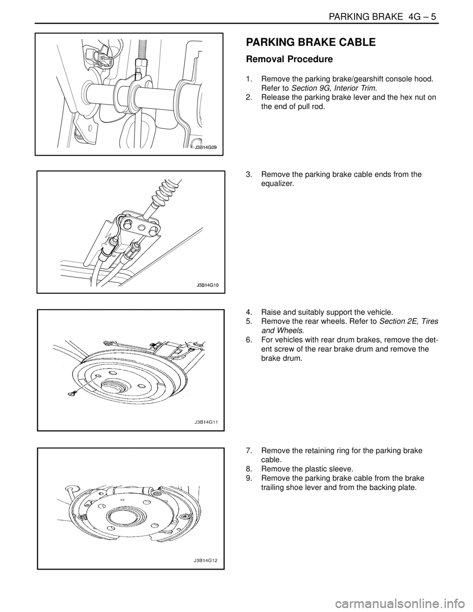
1. Remove the parking brake/gearshift console hood.
Refer to Section 9G, Interior Trim.
2. Release the parking brake lever and the hex nut on
the end of pull rod.
3. Remove the parking brake cable ends from the
equalizer.
4. Raise and suitably support the vehicle.
5. Remove the rear wheels. Refer to Section 2E, Tires
and Wheels.
6. For vehicles with rear drum brakes, remove the det-
ent screw of the rear brake drum and remove the
brake drum.
7. Remove the retaining ring for the parking brake
cable.
8. Remove the plastic sleeve.
9. Remove the parking brake cable from the brake
trailing shoe lever and from the backing plate.
Page 1160 of 2643
4G – 8IPARKING BRAKE
DAEWOO V–121 BL4
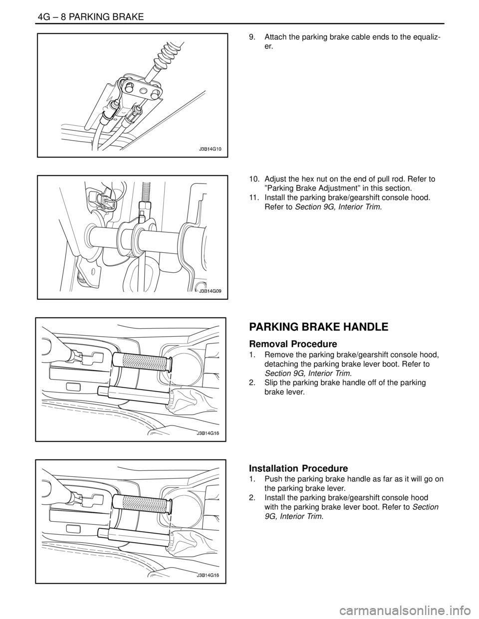
9. Attach the parking brake cable ends to the equaliz-
er.
10. Adjust the hex nut on the end of pull rod. Refer to
”Parking Brake Adjustment” in this section.
11. Install the parking brake/gearshift console hood.
Refer to Section 9G, Interior Trim.
PARKING BRAKE HANDLE
Removal Procedure
1. Remove the parking brake/gearshift console hood,
detaching the parking brake lever boot. Refer to
Section 9G, Interior Trim.
2. Slip the parking brake handle off of the parking
brake lever.
Installation Procedure
1. Push the parking brake handle as far as it will go on
the parking brake lever.
2. Install the parking brake/gearshift console hood
with the parking brake lever boot. Refer to Section
9G, Interior Trim.
Page 1350 of 2643

SECTION : 5A1
ZF 4 HP 16 AUTOMATIC TRANSAXLE
CAUTION : Disconnect the negative battery cable before removing or installing any electrical unit or when a tool
or equipment could easily come in contact with exposed electrical terminals. Disconnecting this cable will help
prevent personal injury and damage to the vehicle. The ignition must also be in LOCK unless otherwise noted.
TABLE OF CONTENTS
INTRODUCTION5A1–3 . . . . . . . . . . . . . . . . . . . . . . . . . . .
ZF 4HP 16 Automatic Transaxle 5A1–3. . . . . . . . . . . .
Transaxle Components 5A1–4. . . . . . . . . . . . . . . . . . . .
SPECIFICATIONS5A1–5 . . . . . . . . . . . . . . . . . . . . . . . . .
General Specifications 5A1–5. . . . . . . . . . . . . . . . . . . .
Transaxle Gear Ratio 5A1–5. . . . . . . . . . . . . . . . . . . . . .
Fluid Capacity 5A1–5. . . . . . . . . . . . . . . . . . . . . . . . . . . .
Fastener Tightening Specifications 5A1–5. . . . . . . . . .
Shift Speed Chart 5A1–7. . . . . . . . . . . . . . . . . . . . . . . . .
Line Pressure 5A1–8. . . . . . . . . . . . . . . . . . . . . . . . . . . .
SPECIAL TOOLS5A1–9 . . . . . . . . . . . . . . . . . . . . . . . . . .
Special Tools Table 5A1–9. . . . . . . . . . . . . . . . . . . . . . .
SCHEMATIC AND ROUTING DIAGRAMS5A1–11 . . .
Transaxle Control Module (1 of 2) 5A1–11. . . . . . . . . .
Transaxle Control Module (2 of 2) 5A1–12. . . . . . . . . .
Shift Mode Diagram 5A1–13. . . . . . . . . . . . . . . . . . . . . .
Power Flow Diagram 5A1–17. . . . . . . . . . . . . . . . . . . . .
COMPONENT LOCATOR5A1–33 . . . . . . . . . . . . . . . . . .
Transaxle Identification Information 5A1–33. . . . . . . .
Torque Converter 5A1–34. . . . . . . . . . . . . . . . . . . . . . . .
Transaxle Housing 5A1–35. . . . . . . . . . . . . . . . . . . . . . .
Oil Pump 5A1–36. . . . . . . . . . . . . . . . . . . . . . . . . . . . . . .
Rear Cover & Oil Pan Cover 5A1–37. . . . . . . . . . . . . .
Parking Lever 5A1–38. . . . . . . . . . . . . . . . . . . . . . . . . . .
Input Shaft & Shift Gear 5A1–39. . . . . . . . . . . . . . . . . .
Valve Body 5A1–41. . . . . . . . . . . . . . . . . . . . . . . . . . . . .
Gear Shift Control 5A1–42. . . . . . . . . . . . . . . . . . . . . . .
DIAGNOSTIC INFORMATION AND PROCEDURES
DIAGNOSIS5A1–43 . . . . . . . . . . . . . . . . . . . . . . . . . . . .
Basic Knowledge Required 5A1–43. . . . . . . . . . . . . . . .
Functional Check Procedure 5A1–43. . . . . . . . . . . . . .
Line Pressure Check Procedure 5A1–43. . . . . . . . . . .
Clutch Plate Diagnosis 5A1–45. . . . . . . . . . . . . . . . . . .
Cooler Flushing and Flow Test 5A1–45. . . . . . . . . . . . . Transaxle Fluid Level Service Procedure 5A1–45. . . .
Electrical/Garage Shift Test 5A1–47. . . . . . . . . . . . . . .
Road Test Procedure 5A1–47. . . . . . . . . . . . . . . . . . . . .
Torque Converter Lock–Up Clutch(TCC)
Diagnosis 5A1–48. . . . . . . . . . . . . . . . . . . . . . . . . . . . .
TCM Initialization Procedure 5A1–50. . . . . . . . . . . . . .
Shift Speed Chart 5A1–51. . . . . . . . . . . . . . . . . . . . . . . .
Internal Wiring Harness Check 5A1–51. . . . . . . . . . . .
Transaxle Wiring Harness Connector 5A1–54. . . . . . .
Symptom Diagnosis 5A1–56. . . . . . . . . . . . . . . . . . . . . .
DIAGNOSTIC TROUBLE CODE DIAGNOSIS5A1–60
Diagnostic Trouble Code (DTC) Identification 5A1–60
DTC P0562 – System Voltage Low 5A1–68. . . . . . . . .
DTC P0563 – System Voltage High 5A1–71. . . . . . . .
DTC P0601 – Internal Control Module Memory
Checksum Error 5A1–74. . . . . . . . . . . . . . . . . . . . . . .
DTC P0603 – Internal Control Module Keep
Alive Memory(KAM) Error 5A1–76. . . . . . . . . . . . . . .
DTC P0604 – Internal Control Module Random
Access Memory(RAM) Error 5A1–78. . . . . . . . . . . . .
DTC P0606 – Transaxle Control Module
Processor Fault 5A1–80. . . . . . . . . . . . . . . . . . . . . . . .
DTC P0703 – Brake Switch Circuit
Malfunction 5A1–83. . . . . . . . . . . . . . . . . . . . . . . . . . .
DTC P0705 – Transmission Range Sensor
Circuit Malfunction(PRNDL Input) 5A1–86. . . . . . . .
DTC P0710 – Transmission Fluid Temperature
Sensor Circuit Malfunction 5A1–89. . . . . . . . . . . . . .
DTC P0715 – Input Speed Sensor(ISS) Circuit
Malfunction 5A1–92. . . . . . . . . . . . . . . . . . . . . . . . . . .
DTC P0716 – Input Speed Sensor(ISS) Circuit
Range/Performance 5A1–95. . . . . . . . . . . . . . . . . . . .
DTC P0717 – Input Speed Sensor(ISS) Circuit
No Signal 5A1–98. . . . . . . . . . . . . . . . . . . . . . . . . . . . .
DTC P0720 – Output Speed Sensor(OSS)
Circuit Malfunction 5A1–101. . . . . . . . . . . . . . . . . . . .
DTC P0721 – Output Speed Sensor(OSS)
Circuit Range/Performance 5A1–104. . . . . . . . . . . . .
Page 1351 of 2643

5A1 – 2IZF 4 HP 16 AUTOMATIC TRANSAXLE
DAEWOO V–121 BL4
DTC P0722 – Output Speed Sensor(OSS)
Circuit No Signal 5A1–107. . . . . . . . . . . . . . . . . . . . . .
DTC P0725 – Engine Speed Input Circuit
Malfunction 5A1–110. . . . . . . . . . . . . . . . . . . . . . . . . .
DTC P0726 – Engine Speed Input Circuit
Range/Performance 5A1–112. . . . . . . . . . . . . . . . . . .
DTC P0727 – Engine Speed Input Circuit No
Signal 5A1–114. . . . . . . . . . . . . . . . . . . . . . . . . . . . . . .
DTC P0731 – Gear 1 Incorrect Ratio 5A1–116. . . . . .
DTC P0732 – Gear 2 Incorrect Ratio 5A1–118. . . . . .
DTC P0733 – Gear 3 Incorrect Ratio 5A1–120. . . . . .
DTC P0734 – Gear 4 Incorrect Ratio 5A1–122. . . . . .
DTC P0781 – 1–2 Shift Malfunction 5A1–124. . . . . . .
DTC P0782 – 2–3 Shift Malfunction 5A1–126. . . . . . .
DTC P0783 – 3–4 Shift Malfunction 5A1–128. . . . . . .
DTC P1604 – Data Check of Internal &
Extended Ram Failed 5A1–130. . . . . . . . . . . . . . . . . .
DTC P1606 – Failure Of External Watchdog 5A1–132
DTC P1671 – CAN Transmit Message
Failure 5A1–134. . . . . . . . . . . . . . . . . . . . . . . . . . . . . . .
DTC P1672 – CAN Bus Off Failure 5A1–136. . . . . . . .
DTC P1673 – CAN Receive ECM Message
Failure 5A1–138. . . . . . . . . . . . . . . . . . . . . . . . . . . . . . .
DTC P1839 – EDS 3 Output Shorted To
Ground 5A1–140. . . . . . . . . . . . . . . . . . . . . . . . . . . . . .
DTC P1840 – EDS 3 Output Shorted To
Power 5A1–142. . . . . . . . . . . . . . . . . . . . . . . . . . . . . . .
DTC P1841 – EDS 3 Output Open 5A1–144. . . . . . . .
DTC P1850 – Solenoid 1 Output Shorted To
Ground 5A1–146. . . . . . . . . . . . . . . . . . . . . . . . . . . . . .
DTC P1851 – Solenoid 1 Output Shorted To
Power 5A1–148. . . . . . . . . . . . . . . . . . . . . . . . . . . . . . .
DTC P1852 – Solenoid 1 Output Open 5A1–150. . . .
DTC P1853 – Solenoid 2 Output Shorted To
Ground 5A1–152. . . . . . . . . . . . . . . . . . . . . . . . . . . . . .
DTC P1854 – Solenoid 2 Output Shorted To
Power 5A1–154. . . . . . . . . . . . . . . . . . . . . . . . . . . . . . .
DTC P1855 – Solenoid 2 Output Open 5A1–156. . . .
DTC P1861 – EDS 4 Output Shorted To
Ground 5A1–158. . . . . . . . . . . . . . . . . . . . . . . . . . . . . .
DTC P1862 – EDS 4 Output Shorted To
Power 5A1–160. . . . . . . . . . . . . . . . . . . . . . . . . . . . . . .
DTC P1863 – EDS 4 Output Open 5A1–162. . . . . . . .
DTC P1864 – EDS 5 Output Shorted To
Ground 5A1–164. . . . . . . . . . . . . . . . . . . . . . . . . . . . . .
DTC P1865 – EDS 5 Output Shorted To
Power 5A1–166. . . . . . . . . . . . . . . . . . . . . . . . . . . . . . .
DTC P1866 – EDS 5 Output Open 5A1–168. . . . . . . .
DTC P1867 – EDS 6 Output Shorted To
Ground 5A1–170. . . . . . . . . . . . . . . . . . . . . . . . . . . . . . DTC P1868 – EDS 6 Output Shorted To
Power 5A1–172. . . . . . . . . . . . . . . . . . . . . . . . . . . . . . .
DTC P1869 – EDS 6 Output Open 5A1–174. . . . . . . .
DTC P1871 – EDS Valve Power Supply
Circuit Shorted to Power 5A1–176. . . . . . . . . . . . . . .
DTC P1874 – Solenoid Valve Power Supply
Circuit Shorted to Power 5A1–178. . . . . . . . . . . . . . .
DTC P1881 – 2–1 Shift Malfunction 5A1–180. . . . . . .
DTC P1883 – 3–2 Shift Malfunction 5A1–182. . . . . . .
DTC P1884 – 4–3 Shift Malfunction 5A1–184. . . . . . .
DTC P1885 – 3–1 Shift Malfunction 5A1–186. . . . . . .
DTC P1886 – 4–2 Shift Malfunction 5A1–188. . . . . . .
MAINTENANCE AND REPAIR5A1–190 . . . . . . . . . . . .
ON–VEHICLE SERVICE 5A1–190. . . . . . . . . . . . . . . . . .
Transaxle Fluid Level Checking Procedure 5A1–190.
Changing the Fluid 5A1–191. . . . . . . . . . . . . . . . . . . . . .
Fluid Level Set After Service 5A1–192. . . . . . . . . . . . .
Repairing Fluid Leaks 5A1–192. . . . . . . . . . . . . . . . . . .
Case Porosity Repair 5A1–193. . . . . . . . . . . . . . . . . . . .
Shift Control Lever Assembly 5A1–193. . . . . . . . . . . . .
Shift Control Cable 5A1–195. . . . . . . . . . . . . . . . . . . . . .
Shift Control Cable Adjustment 5A1–196. . . . . . . . . . .
Transaxle Control Module(TCM) 5A1–197. . . . . . . . . .
Park/Neutral Start Switch 5A1–198. . . . . . . . . . . . . . . .
Oil Cooler Pipes/Hoses 5A1–199. . . . . . . . . . . . . . . . . .
Drive Axle Oil Seal 5A1–201. . . . . . . . . . . . . . . . . . . . . .
Oil Pan, Oil Pan Gasket 5A1–201. . . . . . . . . . . . . . . . .
Control Valve Body Assembly 5A1–203. . . . . . . . . . . .
Left Transaxle Mounting Bracket 5A1–205. . . . . . . . . .
Transaxle Assembly 5A1–206. . . . . . . . . . . . . . . . . . . . .
UNIT REPAIR 5A1–212. . . . . . . . . . . . . . . . . . . . . . . . . . .
Torque Converter 5A1–212. . . . . . . . . . . . . . . . . . . . . . .
Transaxle Holding Fixture Assembly 5A1–212. . . . . . .
Valve Body 5A1–212. . . . . . . . . . . . . . . . . . . . . . . . . . . .
Rear Cover 5A1–213. . . . . . . . . . . . . . . . . . . . . . . . . . . .
Clutch B/E 5A1–214. . . . . . . . . . . . . . . . . . . . . . . . . . . . .
Clutch B/E Measurement Procedure 5A1–217. . . . . .
Planetary Gear Set 5A1–220. . . . . . . . . . . . . . . . . . . . .
Brake C/D 5A1–221. . . . . . . . . . . . . . . . . . . . . . . . . . . . .
Differential 5A1–224. . . . . . . . . . . . . . . . . . . . . . . . . . . . .
Side Shaft 5A1–224. . . . . . . . . . . . . . . . . . . . . . . . . . . . .
Brake F, Slotted Nut 5A1–225. . . . . . . . . . . . . . . . . . . . .
Torque Converter Housing 5A1–227. . . . . . . . . . . . . . .
Shift Mechanism 5A1–228. . . . . . . . . . . . . . . . . . . . . . . .
Parking Lock System 5A1–229. . . . . . . . . . . . . . . . . . . .
Bearing Plate(With Spur Gear) Assembly 5A1–229. .
Oil Pump Assembly 5A1–229. . . . . . . . . . . . . . . . . . . . .
Differential/Side Shaft Outer Race, Bearing
Shim 5A1–230. . . . . . . . . . . . . . . . . . . . . . . . . . . . . . . .