2004 DAEWOO LACETTI heater
[x] Cancel search: heaterPage 2001 of 2643

HEATING AND VENTILATION SYSTEM 7A – 27
DAEWOO V–121 BL4
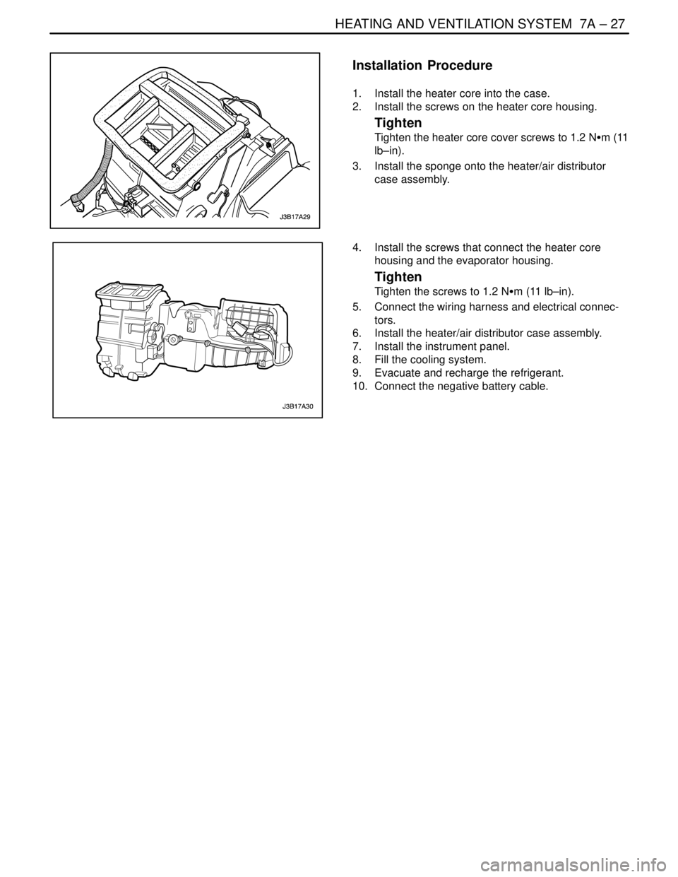
Installation Procedure
1. Install the heater core into the case.
2. Install the screws on the heater core housing.
Tighten
Tighten the heater core cover screws to 1.2 NSm (11
lb–in).
3. Install the sponge onto the heater/air distributor
case assembly.
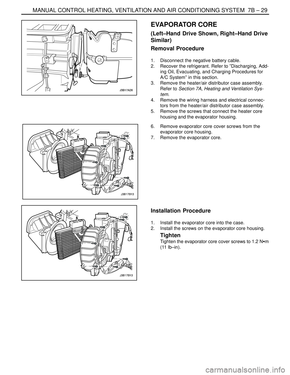
4. Install the screws that connect the heater core
housing and the evaporator housing.
Tighten
Tighten the screws to 1.2 NSm (11 lb–in).
5. Connect the wiring harness and electrical connec-
tors.
6. Install the heater/air distributor case assembly.
7. Install the instrument panel.
8. Fill the cooling system.
9. Evacuate and recharge the refrigerant.
10. Connect the negative battery cable.
Page 2002 of 2643

7A – 28IHEATING AND VENTILATION SYSTEM
DAEWOO V–121 BL4
GENERAL DESCRIPTION
AND SYSTEM OPERATION
HEATING AND VENTILATION
SYSTEMS
The base heater system is designed to provide heating,
ventilation, windshield defrosting, side window defogging,
and on some vehicles, heating directly to the rear seat
area.
The heater and fan assembly blower regulates the airflow
from the air inlet for further processing and distribution.
The heater core transfers the heat from the engine coolant
to the inlet air.
The temperature door regulates the amount of the air that
passes through the heater core. The temperature door
also controls the temperature of the air by controlling the
mix of the heated air and the ambient air.
The mode door regulates the flow and the distribution of
the processed air to the heater ducts and to the defroster
ducts.
This console–mounted heating and ventilation panel con-
tains the following:
The Rotary Temperature Control Knob
1. The Rotary Temperature Control Knob
S Actuates by cable.
S Raises the temperature of the air entering the
vehicle by rotation toward the right, or the red
portion of the knob.
2. The Rotary Blower Control Knob
S Turns ON to operate the blower motor at four
speeds.
S Turns OFF to stop the blower.
S Operates completely independently both from
the mode control that regulates the defroster
door and from the temperature control knob.S Changes the fan speed in any mode and at any
temperature setting.
3. The Rotary Mode Control Knob
S Actuates by cable.
S Regulates the air distribution between the wind-
shield, the instrument panel, and the floor vents.
Two Push Knobs
1. The Rear Window Defogger Push Knob
S Controls the rear window defogger.
S Turns ON the rear window defogger when the
push knob is pressed and the indicator lamp is
illuminated.
2. The A/C Push Knob (if the vehicle is equipped with
air conditioning)
S Controls the A/C.
S Turns the A/C ON when the push knob is down.
However, if the blower control knob is OFF, the
A/C system is OFF, regardless of the position of
the A/C knob.
Fresh Air Control Level Or Push Knob
1. The Fresh Air Control Level
S Operates by cable.
S Switches between recirculating passenger
compartment air and bringing outside air into the
passenger compartment.
S Draws in outside air when the lever is moved to
the right.
S Recirculates inside air when the lever is moved
to the left.
2. The Fresh Air Control Push Knob
S Operates by cable.
S Switches between recirculating passenger
compartment air and bringing outside air into the
passenger compartment.
S Draws in outside air when knob is off.
S Recirculates inside air when the knob is down
with the indicator lamp illuminated.
Page 2004 of 2643

7B – 2IMANUAL CONTROL HEATING, VENTILATION AND AIR CONDITIONING SYSTEM
DAEWOO V–121 BL4
SPECIFICATIONS
GENERAL SPECIFICATIONS
ApplicationUnitDescription
Compressor–V5
Receiver–Dryer–AL R/DRIER
RefrigerantType–R–134a System
Capacityg640±20 (RHD : 680±20)
Refrigerant Oil in A/C SystemType–Union Carbide 488 PAG OIL
Capacitycc (ml)220
Evaporator Capacity (Airflow rate 8.7 kg/min)Kcal/h6000±10%
FASTENER TIGHTENING SPECIFICATIONS
ApplicationNSmLb–FtLb–In
Pressure Transducer7–62
Expansion Valve Stud Bolts8–71
Liquid Pipe Support Clamp Bolts4–35
Liquid Pipe Block–to–Receiver Dryer Retaining Nut1410–
Liquid Pipe Block–to–Expansion Valve Retaining Nut1410–
Refrigerant Discharge Hose Block–to–Condenser Retaining Nut1612–
Refrigerant Discharge Hose Block–to–Compressor Retaining Nut3324–
Evaporator Core Cover Screws1.2–11
Heater Core Housing–to–Evaporator Housing Retaining Screws1.2–11
Suction Hose Block–to–Compressor Retaining Nut3324–
Suction Hose Support Clamp–to–Longitudinal Member Bolt8–71
Suction Hose Support Clamp–to–Engine Bracket Bolt (1.4D, 1.6D only)4–35
Suction Hose Support Clamp–to–Engine Bracket Bolt (1.8D, 2.0D only)1410–
Suction Hose Block–to–Expansion Valve Retaining Nut1410–
(Receiver Dryer) Band Clamp Bolt5–44
Receiver Dryer–to–Condenser Pipe Block Bolt5–44
Upper Compressor–to–Bracket Mounting Bolts (1.4D, 1.6D only)2518–
Lower Compressor–to–Bracket Mounting Bolts (1.4D, 1.6D only)4533–
Front Compressor–to–Bracket Mounting Bolts (1.8D, 2.0D only)3526–
Rear Compressor–to–Bracket Mounting Bolts (1.8D, 2.0D only)2015–
Condenser Mount Bolts4–35
(Compressor) Clutch Plate and Hub Assembly Retaining Nut1713–
(Compressor) Through Bolts10–89
Page 2025 of 2643

MANUAL CONTROL HEATING, VENTILATION AND AIR CONDITIONING SYSTEM 7B – 23
DAEWOO V–121 BL4
SERVICEABLE COMPONENTS
COMPONENTS USED IN NON–A/C
SYSTEMS
Refer to Section 7A, Heating and Ventilation System for
on–vehicle service procedures for the following sections:
S Blower Motor.
S Blower Resistor.
S Control Assembly Knob Lighting.
S Control Assembly.
S Heater Hoses.
S High–Blower Relay.
S A/C Control Vacuum Tank.
S Temperature Control Cable.
S Heater/Air Distributor Case Assembly (A/C Mod-
ule).
S Heater Core
Page 2031 of 2643

MANUAL CONTROL HEATING, VENTILATION AND AIR CONDITIONING SYSTEM 7B – 29
DAEWOO V–121 BL4
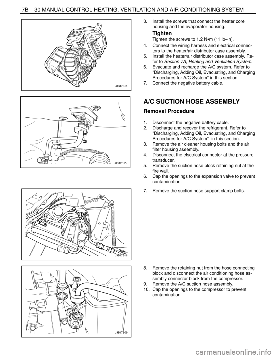
EVAPORATOR CORE
(Left–Hand Drive Shown, Right–Hand Drive
Similar)
Removal Procedure
1. Disconnect the negative battery cable.
2. Recover the refrigerant. Refer to ”Discharging, Add-
ing Oil, Evacuating, and Charging Procedures for
A/C System” in this section.
3. Remove the heater/air distributor case assembly.
Refer to Section 7A, Heating and Ventilation Sys-
tem.
4. Remove the wiring harness and electrical connec-
tors from the heater/air distributor case assembly.
5. Remove the screws that connect the heater core
housing and the evaporator housing.
6. Remove evaporator core cover screws from the
evaporator core housing.
7. Remove the evaporator core.
Installation Procedure
1. Install the evaporator core into the case.
2. Install the screws on the evaporator core housing.
Tighten
Tighten the evaporator core cover screws to 1.2 NSm
(11 lb–in).
Page 2032 of 2643

7B – 30IMANUAL CONTROL HEATING, VENTILATION AND AIR CONDITIONING SYSTEM
DAEWOO V–121 BL4
3. Install the screws that connect the heater core
housing and the evaporator housing.
Tighten
Tighten the screws to 1.2 NSm (11 lb–in).
4. Connect the wiring harness and electrical connec-
tors to the heater/air distributor case assembly.
5. Install the heater/air distributor case assembly. Re-
fer to Section 7A, Heating and Ventilation System.
6. Evacuate and recharge the A/C system. Refer to
”Discharging, Adding Oil, Evacuating, and Charging
Procedures for A/C System” in this section.
7. Connect the negative battery cable.
A/C SUCTION HOSE ASSEMBLY
Removal Procedure
1. Disconnect the negative battery cable.
2. Discharge and recover the refrigerant. Refer to
”Discharging, Adding Oil, Evacuating, and Charging
Procedures for A/C System” in this section.
3. Remove the air cleaner housing bolts and the air
filter housing aseembly.
4. Disconnect the elsctrical connector at the pressure
transducer.
5. Remove the suction hose block retaining nut at the
fire wall.
6. Cap the openings to the expansion valve to prevent
contamination.
7. Remove the suction hose support clamp bolts.
8. Remove the retaining nut from the hose connecting
block and disconnect the air conditioning hose as-
sembly connector block from the compressor.
9. Remove the A/C suction hose assembly.
10. Cap the openings to the compressor to prevent
contamination.
Page 2053 of 2643

MANUAL CONTROL HEATING, VENTILATION AND AIR CONDITIONING SYSTEM 7B – 51
DAEWOO V–121 BL4
GENERAL DESCRIPTION
AND SYSTEM OPERATION
GENERAL INFORMATION
THE V5 A/C SYSTEM
The V5 variable displacement compressor along with the
thermal expansion valve on the evaporator, constitutes a
largely self–regulating system. There is no pressure cycl-
ing switch, no high–pressure cut–off switch and no low–
pressure cut–off switch. The compressor clutch is con-
trolled by the electronic control module (ECM), which
receives data from various engine systems and from a
pressure transducer located in the high–pressure refriger-
ant pipe. In normal operation, the clutch is engaged contin-
uously. Should one of the monitored conditions become
abnormal, the ECM will disengage the compressor clutch
until normal operation is restored. These conditions in-
clude the following:
S Wide–open throttle.
S High engine coolant temperature.
S High engine RPM.
S Refrigerant low pressure.
S Refrigerant high pressure.
The compressor clutch will remain disengaged until nor-
mal operation is established.
SYSTEM
COMPONENTS–FUNCTIONAL
Compressor
All compressors are belt–driven from the engine crank-
shaft through the compressor clutch pulley. The compres-
sor pulley rotates without driving the compressor shaft un-
til an electromagnetic clutch coil is energized. When
voltage is applied to energize the clutch coil, the clutch
plate and hub assembly is drawn rearward toward the
pulley. The magnetic force locks the clutch plate and
pulley together as one unit to drive the compressor shaft.
As the compressor shaft is driven, it compresses the low–
pressure refrigerant vapor from the evaporator into a
high–pressure, high–temperature vapor. The refrigerant
oil which is used to lubricate the compressor is carried with
the refrigerant. Refer to ”V5 Air Conditioning Compressor
Overhaul” in this section.
Condenser Core
The condenser assembly in front of the radiator consists
of coils which carry the refrigerant, and cooling fins that
provide the rapid transfer of heat. The air passing through
the condenser cools the high–pressure refrigerant vapor
and causes it to condense into a liquid.
Expansion Valve
The expansion valve is located with the evaporator core,
on the front passenger side fire wall.
The expansion valve can fail in three different positions:
open, closed, or restricted.
An expansion valve that fails in the open position will result
in a noisy A/C compressor or no cooling. The cause can
be a broken spring, a broken ball, or excessive moisture
in the A/C system. If the spring or the ball are found to be
defective, replace the expansion valve. If excessive mois-
ture is found in the A/C system, recycle the refrigerant.
An expansion valve that fails in the closed position will re-
sult in low suction pressure and no cooling. This may be
caused by a failed power dome or excessive moisture in
the A/C system. If the power dome on the expansion valve
is found to be defective, replace the expansion valve. If ex-
cessive moisture is found in the A/C system, recycle the
refrigerant.
A restricted expansion valve will result in low suction pres-
sure and no cooling. This may be caused by debris in the
refrigerant system. If debris is believed to be the cause, re-
cycle the refrigerant, replace the expansion valve, and re-
place the receiver–dryer.
Evaporator Core
The evaporator is a device which cools and dehumidifies
the air before it enters the vehicle. High–pressure liquid re-
frigerant flows through the expansion tube orifice and be-
comes a low–pressure gas in the evaporator. The heat in
the air passing through the evaporator core is transferred
to the cooler surface of the core, which cools the air. As the
process of heat transfer from the air to the evaporator core
surface is taking place, any moisture or humidity in the air
condenses on the outside surface of the evaporator core
and is drained off as water.
Receiver–Dryer
The sealed receiver–dryer assembly is connected to the
condenser outlet pipe. It acts as a refrigerant storing con-
tainer, receiving liquid, vapor, and refrigerant oil from the
evaporator.
At the bottom of the receiver–dryer is the desiccant, which
acts as a drying agent for the moisture that may have en-
tered the system. An oil bleed hole is located near the bot-
tom of the receiver–dryer outlet pipe to provide an oil re-
turn path to the compressor. The receiver–dryer is
serviceable only as an assembly.
Heater Core
The heater core heats the air before it enters the vehicle.
Engine coolant is circulated through the core to heat the
outside air passing over the fins of the core. The core is
functional at all times and may be used to temper condi-
tioned air in the A/C mode as well as in the heat or the vent
modes.
Page 2054 of 2643

7B – 52IMANUAL CONTROL HEATING, VENTILATION AND AIR CONDITIONING SYSTEM
DAEWOO V–121 BL4
SYSTEM COMPONENTS–CONTROL
Controller
The operation of the A/C system is controlled by the
switches and the lever on the control head. The compres-
sor clutch and the blower are connected electrically to the
control head by a wiring harness. The blower circuit is
open in the OFF mode. Airflow is provided by the four
blower speeds available in the remaining modes. Cooled
and dehumidified air is available in the MAX, NORMAL,
BI–LEVEL, and DEFROST modes.
The temperature is controlled by the position of the tem-
perature knob on the control head. A cable connects this
knob to the temperature door, which controls the airflow
through the heater core. As the temperature knob is
moved through its range of travel, a sliding clip on the
cable at the temperature valve connection should assume
a position ensuring that the temperature door will seat in
both extreme positions. The temperature door position is
independent of the mode control switch. The temperature
door on some models is controlled electrically, eliminating
the need for the temperature cable.
The electric engine cooling fan on some vehicles is not
part of the A/C control system; however, the fan is opera-
tional any time the A/C control is in the MAX, NORMAL,
or BI–LEVEL modes. Some models provide for engine
cooling fan operation when the controller is in the DE-
FROST mode. This added feature is part of the A/C con-
troller function and is aimed at preventing excessive com-
pressor head temperatures. It also allows the A/C system
to function more efficiently. On some models, the engine
cooling fan will be turned off during road speed conditions
above 56 km/h (35 mph), when the airflow though the con-
denser coil is adequate for efficient cooling. The operation
of the cooling fan is controlled by the powertrain control
module (PCM), or the engine control module (ECM),
through the cooling fan relay.
Pressure Transducer
The pressure transducer incorporates the functions of the
high–pressure and the low–pressure cutout switches
along with the fan cycling switch. The pressure transducer
is located in the high–side liquid refrigerant line near the
right front strut tower and the air filter assembly.
Wide–Open Throttle (WOT) Compressor
Cutoff
During full throttle acceleration on vehicles equipped with
multi–port injection (MPI), the throttle position sensor
(TPS) sends a signal to the PCM or the ECM, which then
controls the compressor clutch.
A/C Time Delay Relay
This relay on some vehicles controls the current to the en-
tire A/C system and provides a short delay of A/C opera-
tion upon start–up.
V5 COMPRESSOR–GENERAL
DESCRIPTION
Different vehicles with V5 compressors may exhibit differ-
ences in mounting and installation, but overhaul proce-
dures are similar.
Before removing the compressor or performing on–ve-
hicle repairs, clean the compressor connections and the
outside of the compressor.
Important : After removing a compressor from the vehicle
for servicing, drain the oil by removing the oil drain plug.
Also drain the oil from the suction and the discharge ports
to insure complete draining. Measure the amount of oil
drained, and record that amount. Discard the used oil and
add the same amount of new polyalkaline glycol (PAG) re-
frigerant oil to the compressor.
The compressor has been removed from the vehicle un-
less otherwise indicated.
Clean tools and a clean work area are important for proper
servicing. Keep dirt and foreign material from getting on or
into the compressor parts. Parts that are to be reassem-
bled should be cleaned with trichloroethane, naphtha,
stoddard solvent, kerosene, or equivalent solvents. Dry
the cleaned parts with clean dry air. Use only lint–free
cloths to wipe the parts.
V5 COMPRESSOR–DESCRIPTION OF
OPERATION
The V5 is a variable displacement compressor that can
match the automotive air conditioning (A/C) demand un-
der all conditions without cycling. The basic compressor
mechanism is a variable angle wobble–plate with five ax-
ially oriented cylinders. The center of control of the com-
pressor displacement is a bellows–actuated control valve
located in the rear head of the compressor. The control
valve senses compressor suction pressure.
The wobble–plate angle and the compressor displace-
ment are controlled by the crankcase suction pressure dif-
ferential. When the A/C capacity demand is high, the suc-
tion pressure will be above the control point. The valve will
maintain a bleed from crankcase to suction. With no
crankcase suction pressure differential, the compressor
will have maximum displacement.
When the A/C capacity demand is lower and the suction
pressure reaches the control point, the valve will bleed dis-
charge gas into the crankcase and close off a passage
from the crankcase to the suction plenum. The angle of the
wobble–plate is controlled by a force balance on the five
pistons. A slight elevation of the crankcase suction pres-
sure differential creates total force on the pistons resulting
in a movement about the wobbleplate pivot pin that re-
duces the plate angle.
The compressor has a unique lubrication system. The
crankcase suction bleed is routed through the rotating
wobble–plate for lubrication of the wobble–plate bearing.
The rotation acts as an oil separator which removes some