Page 1246 of 2643
5–86WELECTRICAL WIRING DIAGRAMS
11. ILLUMINATION CIRCUIT
1) ILLUMINATION CIRCUIT – W/O DIMMER CONTROL
a. CONNECTOR INFORMATION
CONNECTOR(NO.)
(PIN NO. COLOR)
CONNECTING, WIRING HARNESSCONNECTOR POSITION
C101 (21 Pin, White)Body � Engine Fuse BlockEngine Fuse Block
C201 (76 Pin, Black)I.P � I.P Fuse BlockI.P Fuse Block
C202 (89 Pin, White)I.P � BodyLeft CO–Driver Leg Room
C208 (15 Pin, White)I.P � FAT CBehind Glove Box
C209 (20 Pin, Black)FAT C � FAT C . A u xBetween Heater Core and Evaporator Core
C210 (6 Pin, White)I.P � ConsoleBelow Console Box
S203 (Red)I.PBehind Audio Mounting
S204 (Magenta)I.PBehind Audio Mounting
G201I.PLeft I.P Fuse Block
G203I.PBehind Left Audio Bracket
b. CONNECTOR IDENTIFICATION SYMBOL & PIN NUMBER POSITION
J3B1P033
Page 1248 of 2643
5–88WELECTRICAL WIRING DIAGRAMS
2) ILLUMINATION CIRCUIT – W/ DIMMER CONTROLa. CONNECTOR INFORMATION
CONNECTOR(NO.)
(PIN NO. COLOR)
CONNECTING, WIRING HARNESSCONNECTOR POSITION
C101 (21 Pin, White)Body � Engine Fuse BlockEngine Fuse Block
C201 (76 Pin, Black)I.P � I.P Fuse BlockI.P Fuse Block
C202 (89 Pin, White)I.P � BodyLeft CO–Driver Leg Room
C208 (15 Pin, White)I.P � FAT CBehind Glove Box
C209 (20 Pin, Black)FAT C � FAT C . A u xBetween Heater Core and Evaporator Core
C210 (6 Pin, White)I.P � ConsoleBelow Console Box
S203 (Red)I.PBehind Audio Mounting
S204 (Magenta)I.PBehind Audio Mounting
G201I.PLeft I.P Fuse Block
G203I.PBehind Left Audio Bracket
b. CONNECTOR IDENTIFICATION SYMBOL & PIN NUMBER POSITION
J3B1P034
Page 1296 of 2643
5–136WELECTRICAL WIRING DIAGRAMS
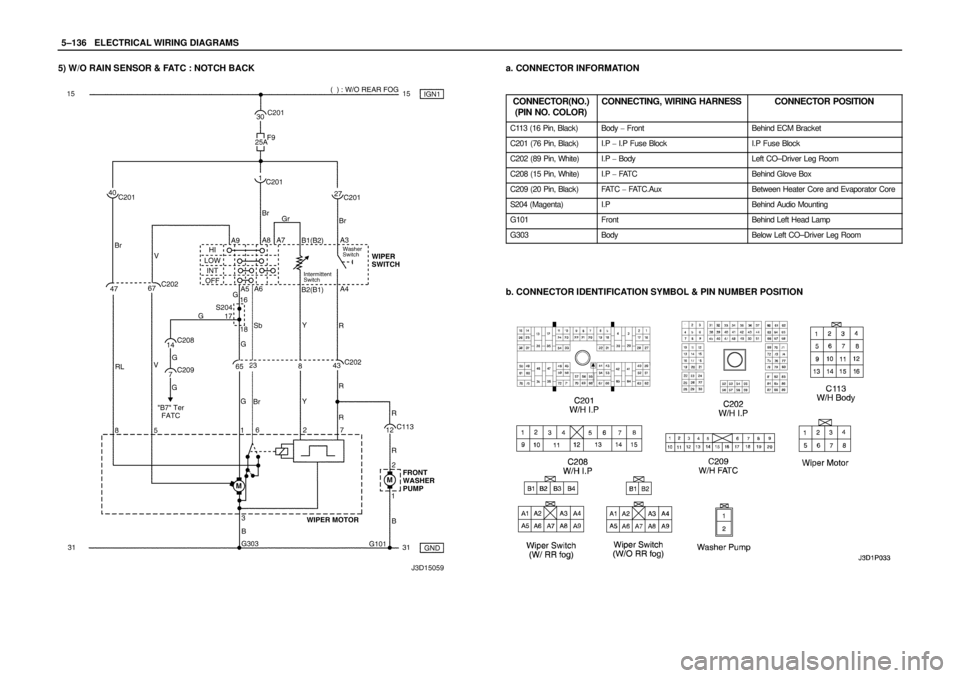
5) W/O RAIN SENSOR & FATC : NOTCH BACKa. CONNECTOR INFORMATION
CONNECTOR(NO.)
(PIN NO. COLOR)
CONNECTING, WIRING HARNESSCONNECTOR POSITION
C113 (16 Pin, Black)Body � FrontBehind ECM Bracket
C201 (76 Pin, Black)I.P � I.P Fuse BlockI.P Fuse Block
C202 (89 Pin, White)I.P � BodyLeft CO–Driver Leg Room
C208 (15 Pin, White)I.P � FAT CBehind Glove Box
C209 (20 Pin, Black)FAT C � FAT C . A u xBetween Heater Core and Evaporator Core
S204 (Magenta)I.PBehind Audio Mounting
G101FrontBehind Left Head Lamp
G303BodyBelow Left CO–Driver Leg Room
b. CONNECTOR IDENTIFICATION SYMBOL & PIN NUMBER POSITION
Page 1298 of 2643
5–138WELECTRICAL WIRING DIAGRAMS
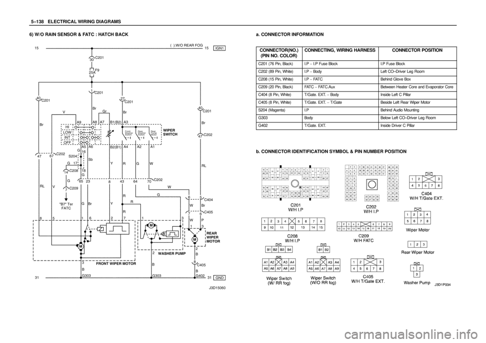
6) W/O RAIN SENSOR & FATC : HATCH BACKa. CONNECTOR INFORMATION
CONNECTOR(NO.)
(PIN NO. COLOR)
CONNECTING, WIRING HARNESSCONNECTOR POSITION
C201 (76 Pin, Black)I.P � I.P Fuse BlockI.P Fuse Block
C202 (89 Pin, White)I.P � BodyLeft CO–Driver Leg Room
C208 (15 Pin, White)I.P � FAT CBehind Glove Box
C209 (20 Pin, Black)FAT C � FAT C . A u xBetween Heater Core and Evaporator Core
C404 (8 Pin, White)T/Gate. EXT. � BodyInside Left C Pillar
C405 (8 Pin, White)T/Gate. EXT. � T/GateBeside Left Rear Wiper Motor
S204 (Magenta)I.PBehind Audio Mounting
G303BodyBelow Left CO–Driver Leg Room
G402T/Gate. EXT.Inside Driver C Pillar
b. CONNECTOR IDENTIFICATION SYMBOL & PIN NUMBER POSITION
Page 1300 of 2643
5–140WELECTRICAL WIRING DIAGRAMS
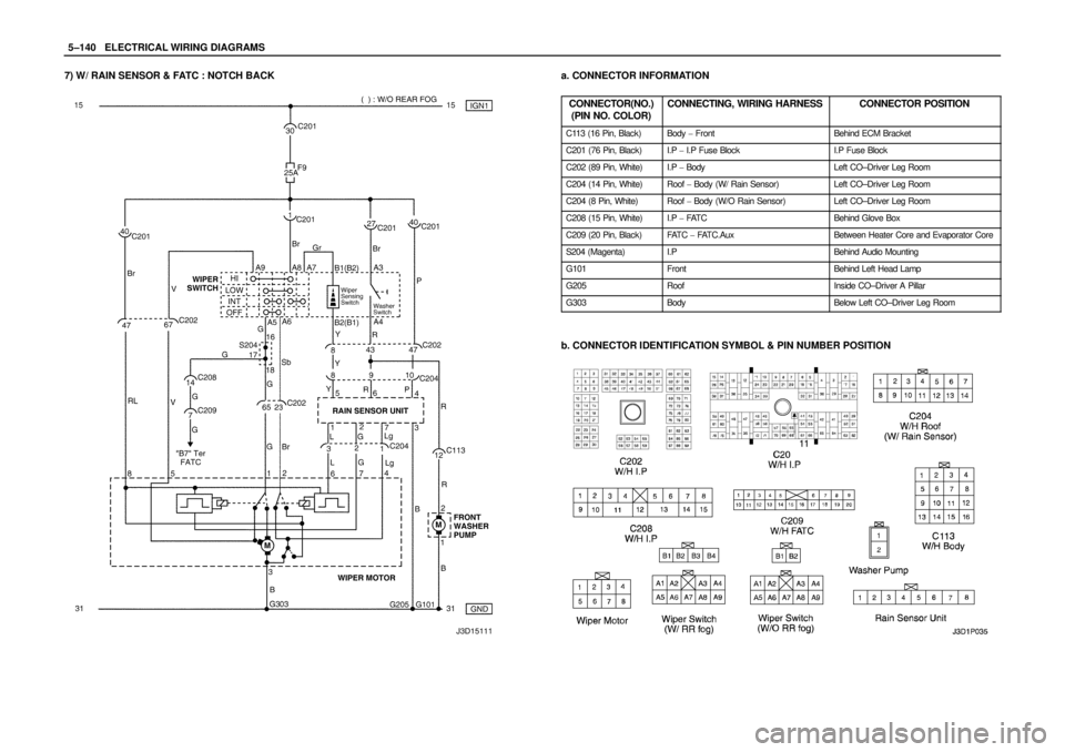
7) W/ RAIN SENSOR & FATC : NOTCH BACKa. CONNECTOR INFORMATION
CONNECTOR(NO.)
(PIN NO. COLOR)
CONNECTING, WIRING HARNESSCONNECTOR POSITION
C113 (16 Pin, Black)Body � FrontBehind ECM Bracket
C201 (76 Pin, Black)I.P � I.P Fuse BlockI.P Fuse Block
C202 (89 Pin, White)I.P � BodyLeft CO–Driver Leg Room
C204 (14 Pin, White)Roof � Body (W/ Rain Sensor)Left CO–Driver Leg Room
C204 (8 Pin, White)Roof � Body (W/O Rain Sensor)Left CO–Driver Leg Room
C208 (15 Pin, White)I.P � FAT CBehind Glove Box
C209 (20 Pin, Black)FAT C � FAT C . A u xBetween Heater Core and Evaporator Core
S204 (Magenta)I.PBehind Audio Mounting
G101FrontBehind Left Head Lamp
G205RoofInside CO–Driver A Pillar
G303BodyBelow Left CO–Driver Leg Room
b. CONNECTOR IDENTIFICATION SYMBOL & PIN NUMBER POSITION
Page 1302 of 2643
5–142WELECTRICAL WIRING DIAGRAMS
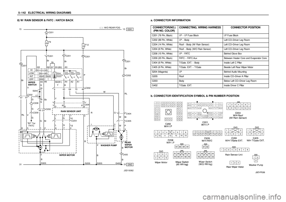
8) W/ RAIN SENSOR & FATC : HATCH BACKa. CONNECTOR INFORMATION
CONNECTOR(NO.)
(PIN NO. COLOR)
CONNECTING, WIRING HARNESSCONNECTOR POSITION
C201 (76 Pin, Black)I.P � I.P Fuse BlockI.P Fuse Block
C202 (89 Pin, White)I.P � BodyLeft CO–Driver Leg Room
C204 (14 Pin, White)Roof � Body (W/ Rain Sensor)Left CO–Driver Leg Room
C204 (8 Pin, White)Roof � Body (W/O Rain Sensor)Left CO–Driver Leg Room
C208 (15 Pin, White)I.P � FAT CBehind Glove Box
C209 (20 Pin, Black)FAT C � FAT C . A u xBetween Heater Core and Evaporator Core
C404 (8 Pin, White)T/Gate. EXT. � BodyInside Left C Pillar
C405 (8 Pin, White)T/Gate. EXT. � T/GateBeside Left Rear Wiper Motor
S204 (Magenta)I.PBehind Audio Mounting
G205RoofInside CO–Driver A Pillar
G303BodyBelow Left CO–Driver Leg Room
G402T/Gate. EXT.Inside Driver C Pillar
b. CONNECTOR IDENTIFICATION SYMBOL & PIN NUMBER POSITION
Page 1304 of 2643

(PIN NO. COLOR)
CONNECTING, WIRING HARNESSCONNECTOR POSITION
C")
5–144WELECTRICAL WIRING DIAGRAMS
20. REAR WINDOW DEFROSTER & OSRV MIRROR HEATING SYSTEM
CIRCUITa. CONNECTOR INFORMATION
CONNECTOR(NO.)
(PIN NO. COLOR)
CONNECTING, WIRING HARNESSCONNECTOR POSITION
C101 (21 Pin, White)Body � Engine Fuse BlockEngine Fuse Block
C102 (11 Pin, White)Body � Engine Fuse BlockEngine Fuse Block
C201 (76 Pin, Black)I.P � I.P Fuse BlockI.P Fuse Block
C202 (89 Pin, White)I.P � BodyLeft CO–Driver Leg Room
C208 (15 Pin, White)I.P � FAT CBehind Glove Box
C209 (20 Pin, Black)FAT C � FAT C . A u xBetween Heater Core and Evaporator Core
C351 (33 Pin, Gray)Body � Front Light DoorUnder CO–Driver A Pillar
C361 (33 Pin, Gray)Body � Front Right DoorUnder Driver A Pillar
C404 (8 Pin, White)T/Gate. EXT. � BodyInside Left C Pillar
C405 (8 Pin, White)T/Gate. EXT. � T/GateBeside Left Rear Wiper Motor
C406 (6 Pin, White)T/Gate. EXT. � T/GateBeside Left Rear Wiper Motor
S302 (Brown)BodyLeft CO–Driver Leg Room
G301BodyBelow Driver Cross Member Floor Panel
G303BodyBelow Left CO–Driver Leg Room
G402T/Gate. EXT.Inside Driver C Pillar
b. CONNECTOR IDENTIFICATION SYMBOL & PIN NUMBER POSITION
Page 1395 of 2643
. This will allow the trans-
axle to be within the correc")
5A1 – 46IZF 4 HP 16 AUTOMATIC TRANSAXLE
DAEWOO V–121 BL4
sible, drive the vehicle for a few kilometers (N–D,
N–R, shift until two gear). This will allow the trans-
axle to be within the correct temperature range.
Transaxle fluid level should be checked at tempera-
ture 20 to 45°C (68 to 113°F).
CAUTION : Removal of the fluid filler plug when the
transaxle fluid is hot may cause injury if fluid drains
from the filler hole.
2. Switch off accessories, especially air conditioner,
heater.
3. With the brake pedal pressed, move the gear shift
control lever through the gear ranges, pausing a
few seconds in each range. Return the gearshift
lever to P(Park). Turn the engine OFF.
4. Park the vehicle on a hoist, inspection pit or similar
raised level surface. The vehicle must be level to
obtain a correct fluid level measurement.
5. Place a fluid container below the fluid filler plug.
6. Clean all dirt from around the fluid filler plug.
Remove the fluid filler plug. Clean the filler plug and
check that there is no damage to the ”O” ring.
S If fluid drains through the filler hole the transaxle
may have been overfilled. When the fluid stops
draining the fluid level is correct. Install the fluid
filler plug and tighten it to 45NSm(34 lb–ft).
S If fluid does not drain through the filler hole, the
transaxle fluid level may be low. Lower the ve-
hicle, and start the vehicle in P(Park) with the
parking brake and the brake applied. With the
engine idling, move the gear shift lever through
the gear ranges, pausing a few seconds in each
range and adding the fluid until gear application
is felt. Return the gear shift lever to P(Park).
Turn the engine OFF and raise the vehicle.
Check if the fluid level is aligned with the bottom
of the filler hole. If not, add a small quantity of
fluid to the correct level. Install the fluid filler
plug and tighten it to 45NSm(34 lb–ft).
7. When the fluid level checking procedure is com-
pleted, wipe any fluid around the filler plug with a
rag or shop towel.
Fluid Level Set After Service
1. Depending on the service procedure performed,
add the following amounts of fluid through the filler
plug hole prior to adjusting the fluid level:
Oil pan removal – 4 liters (4.23 quarts)
Converter removal – 2 liters ( 2.11 quarts)
Overhaul – 6.9liters (7.3 quarts)
Oil drain plug removal – 4 liters (4.23 quarts)
2. Follow steps 1 through 4 of the Fluid Level Diagno-
sis Procedure.
3. Clean all dirt from around the fluid filler plug.
Remove the fluid filler plug. Clean the filler plug and
check that there is no damage to the ”O” ring.
4. Lower the vehicle with the filler plug still removed
and start the vehicle in P(Park) with the parking
brake and the brake applied. With the engine idling,move the gear shift lever through the gear ranges,
pausing a few seconds in each range and adding
the fluid until gear application is felt. Then add an
additional 0.5 liters of fluid. Return the gear shift
lever to P(Park). Turn the engine OFF and raise the
vehicle. Install the fluid filler plug and tighten it to
45NSm (34 lb–ft).
5. Drive the vehicle at 2.2 miles(3.5km) to 2.8
miles(4.5 km) with light throttle so that the engine
does not exceed 2500 rpm. This should result in
the transaxle temperature being in the range 20 to
45°C (68 to 11°F). With the brake applied, move
the shift lever through the gear ranges, pausing a
few seconds in each range at the engine idling.
6. Return the gear shift lever to P(Park). Turn the en-
gine OFF and raise the vehicle on the hoist, if appli-
cable, ensuring the vehicle is level. When the three
minutes passed after the engine stopped, remove
the filler plug. Check if the fluid level is aligned with
the bottom of the filler hole. If not, add a small
quantity of fluid to the correct level. Install the fluid
filler plug and tighten it to 45NSm (34 lb–ft).
7. Wipe any fluid around the filler plug with a rag or
shop towel.
Fluid Leak Diagnosis and Repair
The cause of most external leaks can generally be Lo-
cated and repaired with the transaxle in the vehicle.
Methods for Locating Leaks
General Method
1. Verify that the leak is transaxle fluid.
2. Thoroughly clean the suspected leak area.
3. Drive the vehicle for approximately 25 km (15
miles) or until the transaxle reaches normal operat-
ing temperature (88°C, 190°F).
4. Park the vehicle over clean paper or cardboard.
5. Turn the engine OFF and look for fluid spots on the
paper.
6. Make the necessary repairs to correct the leak.
Powder Method
1. Thoroughly clean the suspected leak area.
2. Apply an aerosol type powder (foot powder) to the
suspected leak area.
3. Drive the vehicle for approximately 25 km (15
miles) or until the transaxle reaches normal operat-
ing temperature (88°C, 190°F).
4. Turn the engine OFF.
5. Inspect the suspected leak area and trace the leak
path through the powder to find the source of the
leak.
6. Make the necessary repairs.
Dye and Black Light Method
1. Add dye to the transaxle though the transaxle fluid
filler plug. Follow the manufacturer’s recommenda-
tion for the amount of dye to be used.
2. Use the black light to find the fluid leak.
3. Make the necessary repairs.
 ILLUMINATION CIRCUIT – W/O DIMMER CONTROL
a. CONNECTOR INFORMATION
CONNECTOR(NO.)
(PIN NO. COLOR)
CONNECTING, WIRING HARNESSCONNECTOR PO")
 ILLUMINATION CIRCUIT – W/ DIMMER CONTROLa. CONNECTOR INFORMATION
CONNECTOR(NO.)
(PIN NO. COLOR)
CONNECTING, WIRING HARNESSCONNECTOR POSITION
C101 (21 Pin, White)")